Nov 6, 2015 - Application developer goes live with the application. Table 2.3: Use Case 2. Deploy the cloud application.
D21.2 Unified architecture for programmable secure computations Project number: Project acronym: Project title: Project Start Date: Duration: Programme: Deliverable Type: Reference Number: Activity and WP:
609611 PRACTICE Privacy-Preserving Computation in the Cloud 1 November, 2013 36 months FP7/2007-2013 Report ICT-609611 / D21.2 / 2.1 Activity 2 / WP21
Due Date:
October 2015 - M24
Actual Submission Date:
6th November, 2015
Responsible Organisation: Editor: Dissemination Level:
CYBER Roman Jagom¨agis Public
Revision:
2.1
Abstract:
This document describes the general architecture for building and using programmable secure computation systems on the cloud.
Keywords:
Architecture, Cloud Application, Secure Computation, Service, Programmable
This project has received funding from the European Unions Seventh Framework Programme for research, technological development and demonstration under grant agreement no. 609611.
Unified architecture for programmable secure computations
Editor Roman Jagom¨agis (CYBER)
Contributors (ordered according to beneficiary numbers) Jonas B¨ohler (SAP) Florian Hahn (SAP) ´ Agnes Kiss (TUDA) Kasper Lyneborg Damg˚ ard(ALX) Peter Sebastian Nordholt (ALX) Reimo Rebane (CYBER) Roman Jagom¨agis (CYBER) Matthias Schunter (INTEL) Bernardo Portela (INESC PORTO) Manuel Barbosa (INESC PORTO) Niels de Vreede (TUE)
Disclaimer The information in this document is provided "as is", and no guarantee or warranty is given that the information is fit for any particular purpose subject to any liability which is mandatory due to applicable law. The users use the information at their sole risk and liability.
PRACTICE D21.2
Page I
Unified architecture for programmable secure computations
Executive Summary The objective of work package WP21 is to provide general architectures for both secure computation services and applications. The idea is to show developers how to combine the deployment and trust models of different cryptographic techniques with programmable secure computation technology to implement information systems with better privacy and security guarantees. Deliverable 21.2 provides the general architecture for building and deploying programmable secure computation systems on the cloud. It finds ways to unify the existing cryptographic technologies and integrate them with the cloud applications and the programming tools in a general way, while taking into account the secure deployment and trust models devised in Deliverable 21.1. The resulting general architecture for the Secure Platform for Enterprise Applications and Services (SPEAR) enables the easy development and deployment of secure cloud applications on top of it, as well as adding and replacing the underlying secure computation and assurance technologies in the applications, as necessary. SPEAR allows to leverage trust and data privacy issues in the cloud computing infrastructure and relies on its Distributed Aggregation and Security Services (DAGGER) sub-platform in order to provide Cryptography-as-a-Service for privacy-sensitive cloud services and applications. As part of this work, we also show how SPEAR & DAGGER can be constructed in a number of alternative ways using different sets of secure computation technologies in each example. The architecture presented in this deliverable is a core contribution of PRACTICE and as such completely new. In this document we mainly focus on defining the general structure for building SPEAR & DAGGER, whereas the detailed description of the parts related to implementation and integration of secure computation techniques into the DAGGER subsystem of SPEAR are presented in deliverable D14.1 [5].
PRACTICE D21.2
Page II
Unified architecture for programmable secure computations
Contents 1 Introduction 1.1 Purpose . . . . . . . . . . . . . . . . . . . . . . . . . . . . . . . . . . . . . . . . 1.2 Scope . . . . . . . . . . . . . . . . . . . . . . . . . . . . . . . . . . . . . . . . . 2 Architectural Drivers 2.1 Overview . . . . . . . . . . . . 2.2 Business Requirements . . . . 2.3 Stakeholders . . . . . . . . . . 2.4 Use Cases . . . . . . . . . . . 2.5 Functional Requirements . . . 2.5.1 Cloud Application . . 2.5.2 Secure Cloud Platform 2.6 Quality Attributes . . . . . .
1 1 1
. . . . . . . .
. . . . . . . .
. . . . . . . .
. . . . . . . .
. . . . . . . .
. . . . . . . .
. . . . . . . .
. . . . . . . .
. . . . . . . .
. . . . . . . .
. . . . . . . .
. . . . . . . .
. . . . . . . .
. . . . . . . .
. . . . . . . .
. . . . . . . .
. . . . . . . .
. . . . . . . .
. . . . . . . .
. . . . . . . .
. . . . . . . .
. . . . . . . .
3 3 4 5 6 12 12 12 13
3 Unified Architecture 3.1 Logical View . . . . . . . . . . . . . . . . . 3.1.1 Overview . . . . . . . . . . . . . . 3.1.2 SPEAR . . . . . . . . . . . . . . . 3.1.3 Application Frontend . . . . . . . . 3.1.4 Application Backend . . . . . . . . 3.1.5 Secure Service Interface . . . . . . 3.1.6 Secure Computation Specification . 3.1.7 Secure Language Compiler . . . . . 3.1.8 Secure Computation Engine . . . . 3.1.9 Computing Virtual Machine . . . . 3.1.10 Secure Computation Protocol Suite 3.1.11 Protocol Suite Frontend . . . . . . 3.1.12 Secure Storage . . . . . . . . . . . 3.1.13 Secure Hardware . . . . . . . . . . 3.1.14 Summary . . . . . . . . . . . . . . 3.2 Process View . . . . . . . . . . . . . . . . 3.2.1 Loading the Frontend . . . . . . . . 3.2.2 Giving Input . . . . . . . . . . . . 3.2.3 Secure Computation . . . . . . . . 3.2.4 Querying for Output . . . . . . . . 3.3 Development View . . . . . . . . . . . . . 3.3.1 Overview . . . . . . . . . . . . . . 3.3.2 SPEAR Application . . . . . . . .
. . . . . . . . . . . . . . . . . . . . . . .
. . . . . . . . . . . . . . . . . . . . . . .
. . . . . . . . . . . . . . . . . . . . . . .
. . . . . . . . . . . . . . . . . . . . . . .
. . . . . . . . . . . . . . . . . . . . . . .
. . . . . . . . . . . . . . . . . . . . . . .
. . . . . . . . . . . . . . . . . . . . . . .
. . . . . . . . . . . . . . . . . . . . . . .
. . . . . . . . . . . . . . . . . . . . . . .
. . . . . . . . . . . . . . . . . . . . . . .
. . . . . . . . . . . . . . . . . . . . . . .
. . . . . . . . . . . . . . . . . . . . . . .
. . . . . . . . . . . . . . . . . . . . . . .
. . . . . . . . . . . . . . . . . . . . . . .
. . . . . . . . . . . . . . . . . . . . . . .
. . . . . . . . . . . . . . . . . . . . . . .
. . . . . . . . . . . . . . . . . . . . . . .
. . . . . . . . . . . . . . . . . . . . . . .
. . . . . . . . . . . . . . . . . . . . . . .
. . . . . . . . . . . . . . . . . . . . . . .
. . . . . . . . . . . . . . . . . . . . . . .
16 16 16 18 22 23 25 26 27 28 28 29 30 31 31 32 34 34 36 38 41 42 42 43
PRACTICE D21.2
. . . . . . . .
. . . . . . . .
. . . . . . . .
. . . . . . . .
. . . . . . . .
. . . . . . . .
Page III
Unified architecture for programmable secure computations
3.4
3.5
3.3.3 DAGGER Core . . . . . . . . . . . . . . . . . . 3.3.4 DAGGER Protocols . . . . . . . . . . . . . . . 3.3.5 SPEAR Hardware . . . . . . . . . . . . . . . . . Deployment View . . . . . . . . . . . . . . . . . . . . . 3.4.1 Overview . . . . . . . . . . . . . . . . . . . . . 3.4.2 SPEAR Instance . . . . . . . . . . . . . . . . . 3.4.3 Cloud Client . . . . . . . . . . . . . . . . . . . . Verification and Integrity . . . . . . . . . . . . . . . . . 3.5.1 Integrity assured by Cryptographic Protocols . 3.5.2 Formal Verification . . . . . . . . . . . . . . . . 3.5.3 Using Hardware-enhanced Security for Integrity
4 Architecture Implementations 4.1 Enterprise web applications . . . . . . . . . . 4.1.1 Example variant with FRESCO . . . . 4.1.2 Example variant with Sharemind . . . 4.2 Standalone CLI and GUI applications . . . . . 4.2.1 Example variant with ABY . . . . . . 4.2.2 Example variant with Sharemind . . . 4.2.3 Example variant with SEEED/HANA 5 Conclusion
PRACTICE D21.2
. . . . . . .
. . . . . . .
. . . . . . .
. . . . . . .
. . . . . . .
. . . . . . . . . . .
. . . . . . . . . . .
. . . . . . . . . . .
. . . . . . . . . . .
. . . . . . . . . . .
. . . . . . . . . . .
. . . . . . . . . . .
. . . . . . . . . . .
. . . . . . . . . . .
. . . . . . . . . . .
. . . . . . . . . . .
. . . . . . . . . . .
. . . . . . . . . . .
. . . . . . . . . . .
44 45 45 46 46 47 48 50 50 52 53
. . . . . . .
. . . . . . .
. . . . . . .
. . . . . . .
. . . . . . .
. . . . . . .
. . . . . . .
. . . . . . .
. . . . . . .
. . . . . . .
. . . . . . .
. . . . . . .
. . . . . . .
. . . . . . .
54 56 56 57 60 60 62 64 66
Page IV
Unified architecture for programmable secure computations
List of Figures 2.1 2.2
The structured requirements diagram with relationships. . . . . . . . . . . . . . The architecturally significant use cases for this architecture. . . . . . . . . . . .
3.1 3.2 3.3 3.4 3.5 3.6 3.7 3.8 3.9 3.10 3.11 3.12 3.13 3.14 3.15 3.16 3.17 3.18 3.19 3.20 3.21
The high-level view on the layered cloud architecture. . . . . . . . . . A decomposed high-level view of the SPEAR architecture. . . . . . . The logical view class diagram for the abstract SPEAR architecture. . The class diagram for Application Frontend. . . . . . . . . . . . . . . The class diagram for Application Backend. . . . . . . . . . . . . . . The class diagram for Secure Service Interface. . . . . . . . . . . . . . The class diagram for Secure Computation Specification. . . . . . . . The class diagram for Secure Computation Protocol Suite. . . . . . . The class diagram for Protocol Suite Frontend. . . . . . . . . . . . . . The class diagram for Secure Hardware. . . . . . . . . . . . . . . . . . The sequence diagram for Loading the Frontend. . . . . . . . . . . . . The communication diagram for Loading the Frontend. . . . . . . . . The sequence diagram for Giving Input. . . . . . . . . . . . . . . . . The communication diagram for Giving Input. . . . . . . . . . . . . . The sequence diagram for Secure Computation. . . . . . . . . . . . . The communication diagram for Secure Computation. . . . . . . . . . The general component view of the architecture. . . . . . . . . . . . . The development package overview of the architecture. . . . . . . . . A high-level deployment view of the SPEAR architecture. . . . . . . . A detailed deployment view of the architecture. . . . . . . . . . . . . A highlighted section of Figure 3.17. . . . . . . . . . . . . . . . . . .
. . . . . . . . . . . . . . . . . . . . .
17 18 21 22 23 25 26 29 30 32 35 35 37 38 40 41 42 44 46 47 53
4.1
The layered architecture combined with PRACTICE partners’ technology artifacts and their possible relationships. . . . . . . . . . . . . . . . . . . . . . . . . The component view with the Java platform and the FRESCO framework. . . . The component view with the Java platform and the Sharemind framework. . . The component view with the Node.js platform and the Sharemind framework. . The component view with the ABY framework. . . . . . . . . . . . . . . . . . . The component view with a standalone client and the Sharemind framework. . .
55 56 58 59 61 63
4.2 4.3 4.4 4.5 4.6
PRACTICE D21.2
. . . . . . . . . . . . . . . . . . . . .
. . . . . . . . . . . . . . . . . . . . .
. . . . . . . . . . . . . . . . . . . . .
. . . . . . . . . . . . . . . . . . . . .
. . . . . . . . . . . . . . . . . . . . .
3 6
Page V
Unified architecture for programmable secure computations
List of Tables 2.1 2.2 2.3 2.4 2.5 2.6 2.7
Stakeholders with their roles and goals. . . . . . . . . . . . . . . . . Use Case 1. Develop the cloud application. . . . . . . . . . . . . . . Use Case 2. Deploy the cloud application. . . . . . . . . . . . . . . Use Case 3. Access the cloud application . . . . . . . . . . . . . . . Use Case 4. Input user data to the cloud application . . . . . . . . Use Case 5. Make a secure query to the cloud application . . . . . . Use Case 6. Deploy secure technology to the secure cloud platform .
. . . . . . .
5 7 8 9 9 10 11
3.1 3.1
The logical components and their responsibilities summarized. . . . . . . . . . . The logical components and their responsibilities summarized. . . . . . . . . . .
32 33
PRACTICE D21.2
. . . . . . .
. . . . . . .
. . . . . . .
. . . . . . .
. . . . . . .
. . . . . . .
Page VI
Unified architecture for programmable secure computations
Chapter 1 Introduction 1.1
Purpose
This document describes the general architecture for building programmable secure computation systems on the cloud. The purpose is to show how to construct a secure cloud platform that allows the use of advanced and practical cryptographic technologies in general purpose cloud applications in order to provide sophisticated security and privacy guarantees of those technologies to all parties in cloud-computing scenarios. The ultimate goal of enabling such capabilities is to remove the need of cloud users to trust their cloud providers for data confidentiality and integrity.
1.2
Scope
Based on the state-of-the-art analysis performed in the PRACTICE deliverable D22.1 [11] we have come to the conclusion, that a significant amount of technological research has been done in the past by the partners of the PRACTICE project and a number of research artifacts relevant to this project exists as a result. Among these artifacts are the programmable secure computation frameworks and techniques, secure database implementations, various secure programming languages, formal verification, as well as software and hardware assurance techniques. By closely inspecting these technologies we have found, that a lot of it, at least partially, has the properties and functionality we would expect from the platform we are building. Thus, it is reasonable to consider stacking and complementing these technologies in a smart way to achieve the platform functionality we require. Based on this knowledge, we attempt to further analyze the cryptographic technologies to find ways to unify their approaches and simplify their integration with cloud applications and programming tools, while taking into account their secure deployment and trust models devised in deliverable D21.1 [13]. As a result of this, we present the Secure Platform for Enterprise Applications and Services (SPEAR) that enables easy development and deployment of secure cloud applications on top of it, as well as adding and replacing the underlying secure computation and assurance technologies in the applications, as necessary. In this document we mainly focus on defining the general structure for building SPEAR, whereas the detailed description of the parts related to implementation and integration of secure computation techniques into the SPEAR system are presented in deliverable D14.1 [5]. We begin by analyzing various architectural drivers that shape the SPEAR architecture in Chapter 2. First, we discuss the general motivation behind this work by stating the business requirements in Section 2.2. We then identify the potential stakeholders and the goals they PRACTICE D21.2
Page 1 of 68
Unified architecture for programmable secure computations
wish to achieve with the system in Section 2.3. Next, we document the use cases involving the stakeholders in Section 2.4. Based on the goals and the use cases we derive the required functionality in Section 2.5 and its characteristics in Section 2.6. We continue by presenting the abstract architecture design of SPEAR in Chapter 3 using a series of architectural views, that capture the functionality from different perspectives. The abstract architecture described in that chapter will be independent of any particular technologies. Finally, we show multiple alternative ways of constructing SPEAR in Chapter 4 using different sets of suitable technology artifacts developed by different research groups. We consider both the existing artifacts from the state-of-the-art as well as the ones to be designed and implemented in PRACTICE.
PRACTICE D21.2
Page 2 of 68
Unified architecture for programmable secure computations
Chapter 2 Architectural Drivers Architectural drivers are the set of requirements that shape the system architecture and have significant influence over the design decisions. They determine which structures to pick for system design, and can be considered the building blocks for decision making. Changing architectural drivers for a developed system is troublesome due to manifold interdependencies in the architecture. Therefore, it is important to get them right very early in the project.
2.1
Overview Actor Define Drive
Goal Is achieved by enabling...
Influence Use Case Is enabled by implementing... Functional Requirement
Quality Attribute ...with these characteristics
Drive Design
Constraint ...with these restrictions
Guide Implementation Is Product
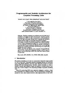
Figure 2.1: The structured requirements diagram with relationships. For this architecture we will consider the business, stakeholder, functional and quality requirements. We first define the business requirements that specify the general objectives and constraints of the architecture and are essential to ensure that the solutions deliver business value and meet business needs. Next we start looking at more specific requirements that are structured in a way shown on Figure 2.1 1 . By identifying the stakeholders, their roles and goals, we determine the users (actors) and what they want to do with the system. The users’ 1
Structured requirements: http://tynerblain.com/blog/2006/05/23/non-functional-requirements-era/ under the CC BY 4.0 license: http://creativecommons.org/licenses/by/4.0/
PRACTICE D21.2
Page 3 of 68
Unified architecture for programmable secure computations
goals can be achieved by enabling certain use cases that consist of the users’ interactions and the expected system responses. From the use cases we then deduce the system’s functional requirements, that need to be implemented in order to enable the use cases. The functional requirements are presented as short and clear descriptions of system’s capabilities (i.e. what the system shall do). Additionally, we consider the Quality Attributes (QA) that define the characteristics of the functional requirements. The QA-s are driven by the goals and their choice may also be influenced by the use cases. The functional requirements drive the architecture’s design choices, that are restricted by constraints, that represent limitations on how a solution must be implemented. The architecture design guides the implementation, which is also the final product.
2.2
Business Requirements
Business requirements are high level goals and requirements that provide value when satisfied, and are typically understood by a management and a board of directors. These describe the general motivation behind the SPEAR architecture from a “business” point of view, and mostly center on cost, schedule, market and marketing considerations. In the following we list the identified business requirements. Requirement B1: Develop the PRACTICE Secure Platform for Enterprise Applications and Services (SPEAR) for providing programmable cryptography and secure computation as a service in cloud infrastructures. Requirement B2: Enable cloud service providers to open new markets, increase their market share, and conquer foreign markets, where reach has been limited due to confidentiality and privacy concerns. Requirement B3: Enable European customers to save costs by globally outsourcing to the cheapest cloud providers while still maintaining guaranteed security and legal compliance. Requirement B4: Allow cloud service providers to reduce their risks of litigation, by making it infeasible for them to perform insider attacks on the data entrusted to them. Requirement B5: Since technology is for the benefit of the user, we need a simple way to explain the security assumptions and guarantees to potential users. Cloud service providers can use this information to explain the unique selling points of their services when compared to standard systems. Requirement B6: Minimize the cost and time of constructing new secure cloud services and applications.
PRACTICE D21.2
Page 4 of 68
Unified architecture for programmable secure computations
2.3
Stakeholders
In this section we identify all the different stakeholders and user roles of the SPEAR system. For each stakeholder we create a user profile including all the roles the users play that are relevant to the system. For each role, we identify all the significant goals the users have that the system will support. The results are presented in Table 2.1 Stakeholder
Roles
Significant goals
Cloud User
Application user
Goal 1: Access/use the cloud application.
Input Party
Goal 2: Provide input data to cloud application for processing and storage. Goal 3: Retain complete control of their data, protecting it from any third party.
Result Party
Goal 4: Get computation result data from the cloud application.
Application developer
Goal 5: Develop the cloud application. Goal 6: Deploy the cloud application. Goal 7: Use secure technologies in its application to address the privacy concerns of cloud users.
Application Service Provider management
Goal 8: Offer service to cloud users, get paid in return. Goal 9: Maintain respect and trust of cloud users.
Secure Technology Developer
Goal 10: Develop secure computation technologies such as secure hardware, secure computation engine, secure computation protocols/techniques. Goal 11: Deploy secure computation technologies to the cloud infrastructure.
Secure Technology Provider management
Goal 12: Offer secure technology as a service, get paid in return. Goal 13: Maintain respect and trust of its customers and partners.
Computing party
Goal 14: Host the runtimes of the application and any supporting platforms. Goal 15: Conduct data processing and storage on behalf of its customers.
Cloud Service Provider management
Goal 16: Offer infrastructure as a service, get paid in return. Goal 17: Maintain respect and trust of its customers and partners.
Application Service Provider
Secure Technology Provider
Cloud Service Provider
Table 2.1: Stakeholders with their roles and goals.
PRACTICE D21.2
Page 5 of 68
Unified architecture for programmable secure computations
2.4
Use Cases
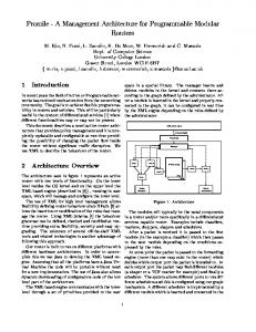
We now describe the possible use cases that need to be enabled by the SPEAR system in order to archive the goals identified in Section 2.3. A use case defines a goal-oriented set of interactions between external actors and the system under consideration. Essentially, use cases capture who (actor ) does what (interaction) with the system and for what purpose (goal ), without dealing with system internals. Both normal and alternative interaction sequences are considered. A complete set of use cases specifies all the different ways to use the system, and therefore defines all behavior required of the system, bounding the scope of the system. Figure 2.2 presents the different architecturally significant use cases. UC 4: Input user data to the cloud application
UC 5: Make a secure query to the cloud application
UC 3: Access the cloud application Cloud User
UC 1: Develop the cloud application
Application Service Provider
UC 2: Deploy the cloud application
Cloud Service Provider
UC 6: Deploy secure technology to the secure cloud platform Secure Technology Provider
Figure 2.2: The architecturally significant use cases for this architecture. We now provide the detailed descriptions for these use cases in the form of tables. For each use case we give the following information: Use Case # The number of a use case followed by its title. Actors The list of main actors involved in the use case. For each actor we name the corresponding stakeholder and its role (as defined in Table 2.1). Goals The goals of the stakeholders (as defined in Table 2.1), that the use case achieves. Brief A short description of the use case. Steps A more detailed description of the use case. Namely, the list of steps defining the main course of action that the stakeholders are supposed to take in order to achieve the goals. Variations An optional field containing a possible alternative course of action. Post-conditions An optional field describing the important conditions that must hold true after the use case has been executed. PRACTICE D21.2
Page 6 of 68
Unified architecture for programmable secure computations
Use Case 1:
Develop the cloud application.
Actors:
Application Service Provider in the role of Application developer Application Service Provider in the role of management Cloud Service Providers
Goals:
5, 7, 9
Brief:
Application developer wants to develop a cloud application that uses advanced cryptography techniques to protect user’s data.
Steps:
1. The management of the Application Service Provider has a cloud business idea and orders its Application developer to implement the idea on the cloud. 2. Application developer looks up the information about SPEAR capabilities of various Cloud Service Providers and selects the most suitable ones. 3. Application developer uses the supported secure programming language and its standard library to specify the algorithms that compute on user data using secure computation technology. 4. The programming language allows the application developer to control when and how much information about the user data is opened in plaintext without requiring any cryptographic knowledge. 5. Application developer uses the supported programming language to specify the general backend logic of the cloud application. 6. Application developer uses the supported programming language to specify the corresponding general frontend logic of the cloud application.
Table 2.2: Use Case 1. Develop the cloud application.
PRACTICE D21.2
Page 7 of 68
Unified architecture for programmable secure computations
Use Case 2:
Deploy the cloud application.
Actors:
Application Service Provider in the role of Application developer Application Service Provider in the role of management Cloud Service Provider (CSP)
Goals:
6, 9, 12, 14, 16
Brief:
Application developer has finished developing the secure cloud application and needs to deploy it to the cloud.
Steps:
1. The management of the Application Service Provider pays Cloud Service Provider(s) to get access to the required secure cloud platform. 2. Each CSP allocates for the Application Service Provider the following SPEAR resources: (a) secure and regular hardware (b) secure platform for running the secure algorithms (c) the necessary application servers, services and tools for running the application backend logic 3. Application developer gets the necessary access information from its management and uses these to access and setup the SPEAR application. 4. Application developer configures the allocated or custom application servers. 5. Application developer configures the secure platform with a subset of available cryptographic techniques. 6. Application developer deploys the backend logic to the application servers. 7. Application developer deploys the secure algorithms to the secure platform. 8. Application developer deploys the frontend logic to the application servers or to digital distribution platform (in case of mobile app). 9. Application developer tests the application 10. Application developer goes live with the application
Table 2.3: Use Case 2. Deploy the cloud application.
PRACTICE D21.2
Page 8 of 68
Unified architecture for programmable secure computations
Use Case 3:
Access the cloud application
Actor:
Cloud User Application Service Provider (ASP) Cloud Service Providers (CSP)
Goals:
1, 8, 15
Brief:
Cloud User wants to access the cloud application service provided by the ASP
Steps:
1. Cloud User types in the web address of the cloud application service hosted at CSP. 2. Cloud User is displayed the frontend logic (the UI) of the cloud application 3. Cloud User can navigate around the cloud application and perform tasks intended by the cloud application. 4. ASP monetizes its cloud application for the offered services.
Variations (optional ):
Cloud User visits the app store platform on his mobile device or a personal computer and downloads the frontend for the cloud application. Table 2.4: Use Case 3. Access the cloud application
Use Case 4:
Input user data to the cloud application
Actor:
Cloud User in the role of Input Party (IP) Application Service Provider (ASP) Cloud Service Providers in the role of Computing Parties (CP)
Goals:
2, 3, 8, 15
Brief:
Input Party wants to input its data securely to the cloud application. 1. IP loads the frontend logic of the cloud application.
Steps:
2. IP uses the capabilities of the frontend logic to securely encrypt its input data. 3. IP uses the frontend logic to securely send the encrypted input data to the CP(s) that host the cloud application of the ASP. 4. The cloud application on each CP securely receives the IP’s inputs and then acts according to the backend logic to either store the received data or initiate a secure algorithm with it. Postconditions:
Nobody but the Input Party has access to its plaintext private input data. Nobody but the original owners of the input data available on the cloud application has access to its plaintext representation.
Table 2.5: Use Case 4. Input user data to the cloud application PRACTICE D21.2
Page 9 of 68
Unified architecture for programmable secure computations
Use Case 5:
Make a secure query to the cloud application
Actor:
Cloud User in the role of Result Party (RP) Application Service Provider (ASP) Cloud Service Providers in the role of Computing Parties (CP)
Goals:
4, 8, 15
Brief:
Result Party wants to make a secure query to the the cloud application to get some results based on available private input data. 1. RP loads the frontend logic of the cloud application.
Steps:
2. RP uses the capabilities of the frontend logic to form a secure query with necessary public and private arguments, encrypting the private ones. 3. RP uses the frontend logic to securely send the query with public and encrypted arguments to the CP(s), that host the cloud application for the ASP. 4. The cloud application on each CP securely receives the RP’s query, and then acts according to the backend logic to initiate a secure algorithm based on the query. 5. CP(s) perform the secure computation on encrypted data using public and encrypted query parameters, and return some public and encrypted results. 6. The cloud application on all CP(s) acts according to backend logic to make the results available to appropriate RP(s). 7. If appropriate, the RP receives the public and encrypted results, and then uses the frontend capabilities to decrypt and display the results. Postconditions:
Nobody but the original owners of the input data available to the cloud application has access to the respective plaintext representations. Nobody learns more new information than it was intended by design of the cloud application.
Table 2.6: Use Case 5. Make a secure query to the cloud application
PRACTICE D21.2
Page 10 of 68
Unified architecture for programmable secure computations
Use Case 6:
Deploy secure technology to the secure cloud platform
Actors:
Secure Technology Provider in the role of Secure Technology Developer (STD) Secure Technology Provider in the role of the Secure Technology Provider management (STP management) Cloud Service Providers (CSP) Application Service Provider
Goals:
11, 12, 13, 14, 17
Brief:
STD has finished developing the secure technology and needs to deploy it as a capability of the SPEAR secure cloud platform at the Cloud Service Providers.
Steps:
1. The STP management has a collaboration opportunity with the Cloud Service Provider(s) by offering secure technology for the secure cloud platform. 2. Each CSP allocates the necessary resources to integrate the following secure technology into its SPEAR infrastructure: (a) secure hardware supporting secure computation on encrypted data and offering hardware assurance (b) secure software based on advanced cryptographic technology allowing to perform secure computation on encrypted data. 3. STD and CSP collaborate to install the mentioned secure technology into the cloud infrastructure in a modular and easily integrable way. 4. STD and CSP collaborate to test the mentioned secure technology. 5. STD and CSP collaborate to go live with the mentioned secure technology. 6. CSP offers the secure technology as part of its programmable secure cloud platform capabilities to the Application Service Providers allowing to develop cloud applications that utilize the advantages provided by the secure technology.
Table 2.7: Use Case 6. Deploy secure technology to the secure cloud platform
PRACTICE D21.2
Page 11 of 68
Unified architecture for programmable secure computations
2.5
Functional Requirements
In this section we list the functional requirements that are required to be implemented in order to enable the use cases described in Section 2.4. A functional requirement is a short but detailed one-sentence statement of a capability of a system, i.e. what the system must be able to do without defining how this is to be accomplished. Functional requirements outline exactly what needs to be delivered and would typically be read by business analysts, developers, project managers and testers.
2.5.1
Cloud Application
A Cloud Application is the a business service that a Cloud User would consume. It is developed by Application Developers (as defined in Section 2.3) on top of Secure Cloud Platform (SPEAR) and deployed on SPEAR-enabled clouds. Requirement F1: The cloud application shall be capable of performing general purpose business logic on its backend. Requirement F2: The cloud application shall be capable of providing a navigable application UI on its frontend. Requirement F3: The frontend and the backend business logic of the cloud application shall be capable of communicating with each other using secure channels. Requirement F4: The cloud application shall be capable of protecting the processed user’s data by the means of secure cloud platform. Requirement F5: The frontend of the cloud application shall be capable of encrypting and decrypting the data according to the cryptographic techniques used by the cloud application. Requirement F6: The cloud application shall be usable from the web, from mobile devices and by the standalone software. Requirement F7: The cloud application shall have the capability to store the necessary data securely.
2.5.2
Secure Cloud Platform
A Secure Cloud Platform is the PRACTICE Secure Platform for Enterprise Applications and Services (SPEAR) for providing cryptography and secure computation as a service for the Cloud Applications. It is developed by Secure Technology Developers (as defined in Section 2.3) and deployed as part of the cloud infrastructures. Requirement F8: The Secure Cloud Platform shall provide a Secure Programming Language for specifying the secure algorithms that compute on encrypted data. Requirement F9: The secure algorithms shall be capable of utilizing the available secure computation technology (both software and hardware) to compute on encrypted data. Requirement F10: The Secure Programming Language shall not require in-depth cryptographic knowledge from the developer of secure algorithms. PRACTICE D21.2
Page 12 of 68
Unified architecture for programmable secure computations
Requirement F11: The Secure Programming Language shall allow to reuse a library of preexisting algorithms to simplify the specification of complex secure computation algorithms. Requirement F12: The Secure Programming Language shall allow the developer to control when and how much encrypted information is opened as plaintext. Requirement F13: The implemented secure algorithms shall be deployable without the need to rebuild the whole application. Requirement F14: The secure algorithms shall be evaluable by request of the cloud application. Requirement F15: The evaluation engine shall be configurable with a set of secure computation techniques. Requirement F16: The evaluation engine shall make the configured secure computation techniques available to the secure algorithms during the evaluation. Requirement F17: The evaluation engine shall allow the use of both the software and the hardware secure computation technologies. Requirement F18: The Secure Cloud Platform shall enable the use of centralized and distributed deployment models of secure computation technologies, as devised in D21.1 [13]. Requirement F19: The evaluation engine shall allow the secure algorithms to store the intermediate or final results in plaintext and encrypted forms. Requirement F20: The evaluation engine shall allow the secure algorithms to access the previously stored plaintext and encrypted data for further processing.
2.6
Quality Attributes
The quality attributes accompany the functional requirements by adding a quality dimension to them. Quality attributes specify the measurable criteria that can be used to judge how well the system must do what it does. We focus on the relevant qualities for the system necessary to cover the functional requirement presented in Section 2.5. For each quality attribute we present a list of requirements and considerations that need to be accounted for while designing the secure cloud platform. Security is the capability of a system to prevent malicious or accidental actions outside of the designed usage, and to prevent disclosure or loss of information while still providing its services to legitimate users. A secure system aims to protect assets and prevent unauthorized modification of the information. In detail, the platform must: • Provide sophisticated security and privacy guarantees for all parties in cloud-computing scenarios. • Remove the need of users to trust their cloud providers for data confidentiality and integrity, as these might not be respected either intentionally or out of negligence. • Protect the privacy of cloud user’s data while storing or processing the data. PRACTICE D21.2
Page 13 of 68
Unified architecture for programmable secure computations
• Remove the ability of insiders to disclose secrets or disrupt the service. Mitigate insider threats and data leakage for computations in the cloud. • Consider techniques that allow computation on encrypted data. These go beyond current approaches that can only protect data at rest within cloud storage in cases where insiders may misbehave. • Consider that the outsourced data and computation might be co-located with the data and computations of other, potentially malicious, clients of the same cloud provider. The cloud service provider might not be able to adequately enforce separation mechanisms between its different customers (tenants). This could enable malicious customers to break the security boundaries between themselves and other customers, or themselves and the cloud provider, and to learn information about the data or computation of other customers. • Consider that while virtualization allows cloud providers to abstract the underlying physical resources and to logically isolate between customers by assigning them virtual domains (VM, separate memory), it does not completely protect from covert and side-channel attacks (e.g. loss of entropy, similar pseudo-random output, isolation failures in cloud infrastructure, shared hardware). • Consider that by wrongly using the cloud, tenants may be unaware of security and privacy vulnerabilities that could unintentionally cause harm to themselves or even to other tenants. • Enable the cloud to build user trust in the information security measures deployed in cloud services. Performance is an indication of the responsiveness of a system to execute any action within a given time interval. It can be measured in terms of latency or throughput. Latency is the time taken to respond to any event. Throughput is the number of events that take place within a given amount of time. The platform should account for the following performance considerations: • Computation on encrypted data is usually one or more orders of magnitude slower compared to computation on plaintext. The cloud applications must account for that and apply practices like vectorization and smart branching to make secure algorithms perform faster. • Cloud applications should make use of parallelization of computation whenever possible in order to bring down computation time. This includes using multiple cloud instances to split the computation effort. Modifiability is the ability of the system to undergo the changes with a degree of ease. These changes could impact components, services, features, and interfaces when adding or changing the functionality, fixing errors, and meeting new business requirements. The platform must: • Allow switching the data protection techniques and implementations in cloud applications. • Allow using new secure data processing algorithms in cloud applications. • Allow using new or updated applications without redeploying the cloud application or the underlying secure computation technologies. PRACTICE D21.2
Page 14 of 68
Unified architecture for programmable secure computations
Usability is concerned with how easy it is for the user to accomplish a desired task and the kind of user support the system provides. The platform must: • Enable a seamless application development process that abstracts the programmer from most, if not all, cryptographic details. This will significantly reduce the learning curve for development of secure cloud applications so that developers would not be required to have cryptographic training. This, in turn, will help save costs in the most expensive part of application development and ease the deployment of secure and private cloud applications. Compatibility is the ability of the system to work with other systems. The platform must: • Support multiple end user platforms: web interfaces, mobile devices, desktops and server systems. • Allow to deploy the secure cloud platform on any cloud infrastructure. • Allow using any storage facility in the platform and applications. • Allow to implement the secure cloud platform using different technology providers. Testability Is the ability of the system to be tested before deployment. The platform must: • Allow for automatic testing of the cloud application locally and on a test deployment. • Allow for automatic testing of the individual modules within SPEAR.
PRACTICE D21.2
Page 15 of 68
Unified architecture for programmable secure computations
Chapter 3 Unified Architecture This chapter describes the general architecture for the SPEAR platform that conforms with the previously identified architectural drivers. The essence of the system is captured from a number of architectural viewpoints, each analyzing and describing the design from a different perspective. The two conceptual level views (Logical and Process views) capture the static structure and dynamic behavior of the system, while the two physical level views (Development and Deployment views) explain the mapping of the logical structure and processes into physical components and environments. We begin by looking at the system from the high level and then continue zooming into the architecture to unveil more details.
3.1
Logical View
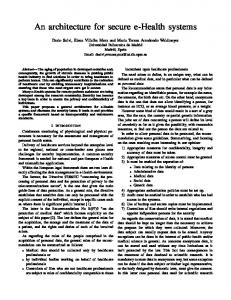
The logical view describes the architecturally significant parts of the static design model. We present the overall decomposition of the system in terms of its package hierarchy, layers and classes, discuss their responsibilities and show how the functional requirements are realized in their relationships.
3.1.1
Overview
Cloud computing is a model for on-demand delivery of scalable and virtualized computing resources to business applications. Cloud services provide users and enterprises with various capabilities to store and process their data in third party data centers. While allowing the users to efficiently and flexibly benefit from the offered technologies, these services also reduce the infrastructure maintenance and application development costs. As a result, organizations and individuals choose to outsource their data to the cloud, where an untrusted party is in charge of storage and computation. Cloud Service Providers provide cloud computing services via a layered delivery model that consists of three basic layers stacked on top of each other as shown in Figure 3.1 and briefly described below. Infrastructure-as-a-Service (IaaS) provides access to the lowest level data center hardware resources, such as computing power, storage and network, in an easy-to-consume way, allowing to run the existing workloads on the cloud without any additional software rearchitecting. The main enabling technology for this layer is virtualization. Virtualization software called hypervisor abstracts and separates a number of physical computing devices into one or more “virtual” devices, so that each can be easily used and managed to perform PRACTICE D21.2
Page 16 of 68
Unified architecture for programmable secure computations
SP
EA
R
Cloud Client
Figure 3.1: The high-level view on the layered cloud architecture. computing tasks. The amount and kinds of resources allocated to each virtual device can be chosen and scaled up or down dynamically according to customers’ needs. An operating system and business applications are installed and run on the virtual devices. Cloud providers bill the IaaS service based on the amount of resources allocated and consumed. Platform-as-a-Service (PaaS) provides a platform for developing and deploying applications in the cloud. It offers a set of services and the development environment that abstract the application software and hardware infrastructure (such as the servers, operating system, middleware and configuration details), allowing customers to provision, develop, test, stage and monitor applications without the complexity of managing the infrastructure typically associated with these processes. By providing the development platform, facilitating application deployment, and streamlining application life-cycle, PaaS gives developers the ability to rapidly consume IaaS and improves the time to market with minimal capital costs. PaaS also allows developers to extend their applications with various specialized functionality only available in the cloud and delivered as services through the PaaS platform. Software-as-a-Service (SaaS) provides on-demand application services that users can access, and relies on the PaaS to manage the infrastructure needed to instantiate and run the services, simplifying the maintenance and support. SaaS applications can scale and request features on demand, and are rolled out frequently, which makes them easy to integrate with existing applications and systems. There is no need to deploy or maintain the service software as this is done automatically. A single service instantiation can be shared by multiple tenants depending on functionality or load balancing needs. SaaS services are typically billed on a pay-per-use or subscription basis, which simplifies the licensing matters. In the following we present the general architecture for the Secure Platform for Enterprise Applications and Services (SPEAR), that covers all the layers of the cloud delivery model discussed above, allowing to leverage trust and data privacy issues in the cloud computing infrastructure. SPEAR relies on the Distributed Aggregation and Security Services (DAGGER) sub-platform in order to provide Cryptography-as-a-Service for privacy-sensitive cloud services and applications. We focus on the parts of the architecture necessary for building SPEAR. The sections below will further decompose the architecture into packages, layers and significant classes, as shown in Figure 3.2 and Figure 3.3. PRACTICE D21.2
Page 17 of 68
Unified architecture for programmable secure computations
3.1.2
SPEAR
The PRACTICE Secure Platform for Enterprise Applications and Services (SPEAR) provides a cryptographically secure computation platform as a service for cloud applications and services. The purpose is to protect user data from unauthorized access from cloud providers and other users in the cloud setting, while still allowing business applications to benefit from the information contained in the data. To provide this kind of security, SPEAR complements the layered cloud delivery model discussed earlier with security components and corresponding interfaces to the cloud. The cloud infrastructure together with SPEAR’s securty components and interfaces allow developers to design and implement cloud applications based on different trust, security and privacy requirements. Cloud Client SPEAR
Application Service DAGGER
Secure Service Interface
Secure Data Analysis Algorithms
Computing Virtual Machine
Secure Computation Protocols
Secure Storage
Cloud Infrastructure
Figure 3.2: A decomposed high-level view of the SPEAR architecture. As displayed in Figure 3.2, SPEAR consists of security related cloud infrastructure hardware resources, the Distributed Aggregation and Security Services (DAGGER) security sub-platform, the formal verification module, and the application service layer. The entire package works across a number of heterogeneous Cloud Client devices providing a common platform to securely access the cloud. From application developers’ point of view, the SPEAR technology stack is hosted on the cloud in a Platform-as-a-Service model allowing to create secure cloud applications on top of it. The developers can select the most suitable combination of SPEAR mechanisms to address their specific security needs. SPEAR is responsible for setting up the desired DAGGER and Cloud Infrastructure and running applications utilizing these. The corresponding setup and configuration processes are abstracted from the cloud user, increasing the ease of use and the overall security of the system. Later in Chapter 4 we describe a number of alternative ways to construct SPEAR. In the following subsections we describe the layers of the SPEAR architecture in a bit more detail. PRACTICE D21.2
Page 18 of 68
Unified architecture for programmable secure computations
Cloud Client A Cloud Client is a non-cloud application or device used to control and otherwise interact with the cloud system. The client should make it easy for its users to work with a SPEAR-enabled clouds and applications. The client can be seen as used by the Cloud User and/or the Application Service Provider stakeholders as described in the table in Section 2.3. For the Cloud User the client is the user interface used for accessing the cloud application, providing input data and viewing the results. For the Application Service Provider the client should allow uploading new applications to the SPEAR-enabled cloud and configuring existing applications running on the cloud. The Cloud Client could be implemented as e.g. a web-interface, a mobile application or a command line interface (CLI). Application Service An Application Service should be seen as a Software-as-a-Service (SaaS) layer, which enables Application Service Providers to easily develop and roll out new SPEAR applications, that Cloud Users can consume. The idea is to separate the general purpose application from the actual secure computation logic, enabling the developers to either switch the underlying security engine or reuse the application across multiple different instances of SPEAR. This layer contains both the required software for running the rolled out applications, as well as the application itself. DAGGER The PRACTICE Distributed Aggregation and Security Services (DAGGER) is the key subsystem of SPEAR that represents the middleware for using cryptographically secure computing in PaaS/SaaS cloud applications, and this way achieving increased security guarantees. DAGGER can be seen as a Platform-as-a-Service (PaaS) layer, and in particular exposes the following features: • Libraries for integrating with cloud applications and user interfaces. • A high-level language for specifying secure data analysis algorithms in applications. • A compiler for the DAGGER language. • A set of (possibly advanced) algorithms that can be used in applications. • A set of secure computation protocols for computing on encrypted data. • A programmable security engine capable of executing secure computation protocols according to algorithm specification. • Secure data storage compatible with secure computing. DAGGER is responsible for performing secure computation according to specified algorithms. Based on requirements listed in Section 2.5, the platform offers a language, a compiler and a library of standard algorithms that non-cryptographers can use for specifying the secure algorithms necessary for the applications. The compiler converts the high-level language into specifications understandable by the DAGGER engine, such that these can be executed.
PRACTICE D21.2
Page 19 of 68
Unified architecture for programmable secure computations
The DAGGER service is used by the Application Service layer via the provided libraries and interfaces. Because of the nature of the underlying cryptographic mechanisms of secure computation, DAGGER is built as a distributed service, that may communicate with other configured DAGGER nodes over the network. For that reason, the whole SPEAR stack may have to be replicated accordingly. While it should be possible to plug in a different DAGGER in the application, doing so might alter the requirements for the application and the underlying Cloud Infrastructure. This makes the applications to some extent dependent on the properties of a concrete DAGGER, and the changes in its configuration must be carefully evaluated for each application. Finally, DAGGER is also responsible for storing persistent data such as user input and pre-generated data in a way compatible with secure computing. In Chapter 4 we describe several versions of SPEAR based on different DAGGER implementations. Also, the architecture of components and interfaces for integrating cryptographic techniques into the DAGGER secure computing platform can be found in PRACTICE deliverable D14.1 [5]. A concrete implementation of these interfaces is reported in deliverable D14.2 [4]. Formal Verification Another component in SPEAR is the formal verification module that includes mathematical methods and techniques, as well as tools, used to establish verifiable assurance of the soundness of the DAGGER secure computation platform on its various levels, and to perform a quantitative evaluation of the deployed security technology and software. The Section 3.5 will go into the details of this feature of SPEAR. Cloud Infrastructure The Cloud Infrastructure of SPEAR belongs to the Infrastructure-as-a-Service (IaaS) layer that enables the upper layers to run on (virtualized) hardware. IaaS is configured with specific resources, such as specialized security hardware modules, required by particular DAGGER subsystems that SPEAR applications build on. These resources further improve security and performance in applications, and can be offered as a service together with standard computing power, storage and network resources. SPEAR should be able to access these resources from its other layers. Another intention here is to develop DAGGER separately from the infrastructure, so that it can be integrated to various cloud platforms. This will allow to cover larger market. However, due to the potential demands (either because of SPEAR or DAGGER components) to the Cloud Infrastructure, such as special hardware requirements, the amount of potential cloud providers the customers can choose from would be limited. Class Diagram A general class diagram of SPEAR is presented in Figure 3.3. It shows full decomposition of the architecture into classes and relationships among them. In the following sections we are going to describe the responsibilities of classes as well how these relate to each other. A summarizing table will be provided in Section 3.1.14.
PRACTICE D21.2
Page 20 of 68
Application Backend Interface
Application Backend Logic
rely on supported secure queries
Application UI
access
1
Application Frontend Logic
has 1
access
maintain
query
one of
query
load
encrypt/decrypt data
access
DAGGER Secure Storage
Secure Storage Interface
Secure Computation Specification
Maintenance Interface
access
Query Interface
PSF Interface +init(cfg : string) +deinit() +getTypes() : Data Type []
Data Type +name() : string +sizePublic() : short +sizeSecret() : short +encrypt(in : Arg [], out : Arg []) : boolean +decrypt(in : Arg [], out : Arg []) : boolean
Protocol Suite Frontend -types : Data Type[]
Data Type Impl
Secure Service Interface
specified with
load access SCS Format
evaluate
Secure Computation Engine -Computing Virtual Machine
call
compile
1
load
compatible with 1
Secure Language Compiler
access
link
Protocol
Protocol Suite
1..* 1
access
Page 21 of 68
Secure Hardware Interface
Secure Hardware Driver
Figure 3.3: The logical view class diagram for the abstract SPEAR architecture.
Arg -data : byte[] -size : long
Unified architecture for programmable secure computations
PRACTICE D21.2
SPEAR
Unified architecture for programmable secure computations
3.1.3
Application Frontend
An Application Frontend is the part of the SPEAR Application Service layer that acts as a client side access point to the SPEAR cloud application that a Cloud User would use via his Cloud Client. It provides the user with an Application User Interface as well as Application Frontend Logic and mechanisms required to access and interact with the Application Backend through its interface on the cloud, as shown in Figure 3.4. SPEAR Application Backend Interface
access
DAGGER
Application Frontend Logic
query
load
access
Query Interface
Protocol Suite Frontend -types : Data Type[]
PSF Interface +init(cfg : string) +deinit() +getTypes() : Data Type []
Application UI
encrypt/decrypt data
Data Type +name() : string +sizePublic() : short +sizeSecret() : short +encrypt(in : Arg [], out : Arg []) : boolean +decrypt(in : Arg [], out : Arg []) : boolean
Figure 3.4: The class diagram for Application Frontend. In a typical scenario the Application Frontend would be realized as an HTML/CSS/JavaScript web interface accessed via a standard web browser. This means the Cloud User would provide inputs to the application by submitting web forms and view the results and other application specific information as pages in his browser. However, in other scenarios the Application Frontend could take different forms, such as a standalone (CLI, GUI, mobile) application, or even an add-on/plug-in library to such applications. Depending on the configuration of a SPEAR cloud application the Application Frontend may communicate with one or more SPEAR nodes. Similarly, the inputs and outputs must be securely and correctly processed in a way compatible with a particular SPEAR configuration (i.e. the DAGGER protocols and their deployment model). For this purpose the Application Frontend is served with the configuration of the SPEAR application, and a set of Protocol Suite Frontend plug-ins (described in Section 3.1.11) that it uses via PSF Interface and Data Type interface to encrypt the clear-text inputs indented to be secret before sending and decrypt the secret outputs of the application before presenting them to the Cloud User. In some SPEAR configurations, due to technological specifics of DAGGER, the Application Frontend Logic may access the DAGGER service directly, bypassing the Application Backend. In these cases the frontend is supplied with and uses the Query Interface (described in Section 3.1.5) of DAGGER in order to interact with it, and may even participate in secure computation. In web-based cloud applications, however, this is not the case, and such interaction flows through the Application Backend, allowing for more elaborate secure applications in the cloud. Responsibilities: • Provide an Application UI. • Access and interact with the SPEAR Application Backend. PRACTICE D21.2
Page 22 of 68
Unified architecture for programmable secure computations
• Apply Protocol Suite Frontend plug-ins to securely process inputs and outputs.
3.1.4
Application Backend
An Application Backend is the server side part of the SPEAR Application Service layer that runs on the cloud infrastructure. It consists of the Application Backend Logic representing the general purpose application business logic, and the Application Backend Interface that it implements allowing the Application Frontend in the Cloud Client to access the application logic (see Figure 3.5). SPEAR Application Backend Interface
rely on supported secure queries
DAGGER
Secure Computation Specification
Application Backend Logic
access
Secure Storage Interface
maintain
Maintenance Interface
query
Query Interface
Figure 3.5: The class diagram for Application Backend. In the cloud scenario the Application Backend would almost always be a web service (e.g. using Representational State Transfer (REST) APIs), although other existing and new inter-process communication technologies can be used. The Application Backend Logic is developed using any general purpose programming language and/or platform suitable for building cloud services. It is up to the Application Developer to configure the entry point of SPEAR in a way such that the users have to make the least amount of choices to use the application service. The Application Backend builds around the tools and technologies of the DAGGER platform, that it uses through corresponding interfaces in order to provide security in applications. The Application Backend is “context-unaware” in the sense that it does not know about the details of the DAGGER’s configuration. These are abstracted from the application and handled by DAGGER internally. The whole application package can be served in two different ways: i) as a standalone business application, or ii) as a configurable Software-as-a-Service built around the business application. We will now discuss each option separately. Business Application The first option is that the Application Backend represents a standalone Business Application built to serve a specific business purpose using a particular DAGGER configuration. The Application Backend Logic is programmed so that it knows exactly the data model and which elements in it represent sensitive information. It executes the general purpose business logic in clear-text and uses DAGGER functionality to securely process the sensitive data in encrypted form. The secure data analysis algorithms for processing sensitive data are expressed as Secure Computation Specifications (see Section 3.1.6). The Application Developers may use the DAGGER PRACTICE D21.2
Page 23 of 68
Unified architecture for programmable secure computations
secure language (see Section 3.1.7) to implement custom tailored algorithms for their application, or rely on some pre-defined algorithms already included in the DAGGER platform. The Application Backend Logic is aware of the available algorithms and queries their execution by the DAGGER layer using the Query Interface (described in Section 3.1.5). The backend logic may use DAGGER’s secure storage via the Secure Storage Interface to store and retrieve public and private application data. It may also contact the Application Frontend in case user input is required. Responsibilities: • Communicate with the Application Frontend. • Perform general business logic in clear-text. • Query the DAGGER system to process sensitive data in encrypted form. • Come with custom secure data analysis algorithms. • Use the Secure Storage module. General Service The second option builds around the previous Business Application option and serves it in a higher level Software-as-a-Service (SaaS) model. In this case the Application Backend Logic is developed in a way that allows constructing different Business Applications based on some predefined application service framework and then rolling these out as separate application instances for a fee. An example of such a service would be a hypothetical secure survey application (e.g., based on the prototype described in the deliverable D23.1 [14]) that provides the framework for creating surveys based on desired configuration of the DAGGER layer and allows deploying these separately on the cloud. The granularity and flexibility of application service building blocks may vary, potentially allowing to construct very different applications based on the same service. In SaaS case, the Application Backend Logic should be able to setup and maintain the DAGGER according to some configuration. This can be done via the Maintenance Interface. There are various configuration aspects to DAGGER. Below we present a list of examples, that is not exhaustive nor are all bullets necessarily required: • Location of other SPEAR nodes. • Credentials for secure communication. • The protocols DAGGER should support. • Secure Storage options. Responsibilities: • Communicate with the Application Frontend to configure an application • Instantiate, manage and configure Business Applications • Create, manage and configure DAGGER instances PRACTICE D21.2
Page 24 of 68
Unified architecture for programmable secure computations
3.1.5
Secure Service Interface
A Secure Service Interface (SSI) is the interface library for integrating DAGGER into the SPEAR applications services. The library allows SPEAR applications to setup and communicate with the Secure Computation Engine (SCE) (see Section 3.1.8) of the DAGGER platform. For these purposes SSI implements the Maintenance Interface and the Query Interface respectively, as displayed in Figure 3.6. SPEAR Application Backend Logic
1
Application Frontend Logic
has 1
maintain
query
one of
query
DAGGER Maintenance Interface
Query Interface
Secure Service Interface access Secure Computation Engine -Computing Virtual Machine
Figure 3.6: The class diagram for Secure Service Interface. The Maintenance Interface is targeted towards the Software-as-a-Service type of Application Backend Logic and provides capabilities required for managing and facilitating the deployment of SCE instances. More specifically, the interface allows configuring and instantiating an SCE on the cloud infrastructure with a set of Protocol Suites (described in Section 3.1.10), specifying their node topology, the credentials for secure network communication, and other settings relevant for the particular SCE implementation. The interface also allows to gracefully shut down the created SCE instances. The Query Interface is used either by the Business Application type of Application Backend Logic or the Application Frontend Logic to make secure queries to the deployed SCE instances. Depending on the DAGGER implementation the queries are formed using a command API or a query language (e.g. inspired by query languages like SQL or MDX) exposed by the Query Interface. A query would trigger an SCE to execute a number of integrated data processing procedures expressed as Secure Computation Specifications (see Section 3.1.6) and available to the SCE instances. The typical queries would involve providing input data (both public and secret) and requesting secure computations on the combination of these and the data stored in Secure Storage. If the expressive power of a query language allows, the queries may dynamically trigger rather complex aggregations and data mining algorithms, that otherwise would have to be specified as dedicated procedures. Once the SCE completes the query request, the results are also made available via the Query Interface. The Secure Service Interface can be implemented either as a standalone component (tool or library) or an API. The standalone option would assume some kind of inter-process communication protocol between the SSI and an SCE instance, such as Remote Procedure Call (RPC) or a Transmission Control Protocol (TCP), and therefore, support being used on the client PRACTICE D21.2
Page 25 of 68
Unified architecture for programmable secure computations
side of an application. Whereas the API version would tightly couple the SSI/SCE with the Application Backend in a single package and is, hence, less flexible. An SSI would typically be specific to a particular DAGGER implementation. However, it could be possible to create an SSI that all DAGGERs understand. In this case each DAGGER would be required to implement the translation module from an abstract SSI to its own version of SSI. This would also increase the potential for reusability of applications. Responsibilities: • Provide interface for setting up the DAGGER SCE instances. • Provide interface for making secure queries to the SCE.
3.1.6
Secure Computation Specification
A Secure Computation Specification (SCS) is the representation of integrated data processing procedures of the DAGGER platform. It corresponds to the Secure Data Analysis Algorithms layer of the SPEAR platform, and contains the business logic (i.e. arbitrary functions on private data) that a SPEAR application requires to compute securely. DAGGER
specified with
S e c u re C o m pu tat i o n Specification
SCS Format
load
evaluate
Secure Computation Engine -Computing Virtual Machine
compile
Secure Language Compiler
Figure 3.7: The class diagram for Secure Computation Specification. The Secure Computation Specifications are expressed according to a pre-defined SCS Format, that can be understood and evaluated by the Secure Computation Engine (see Figure 3.7). For increased performance a preferable format would be something low level, such as a byte-code or, in some cases, even generic native machine code, that the Computing Virtual Machine of an SCE can efficiently operate with. To simplify the development of secure applications, the Secure Computation Specifications can be specified and compiled using a high level language as discussed in Section 3.1.7. An SCS operates with relatively high-level secure computation primitives, such as secure operations represented by the DAGGER Secure Computation Protocols (see Section 3.1.10), that abstract away any cryptographic implementation specifics internal to the protocols. For example an SCS may express a program computing the average over n secret integers using an appropriate set of secure operations (e.g. addition and division, or a single atomic operation for computing an average), but it does not deal with randomness and sending messages between computing parties according to some secure computation scheme. The latter is delegated to the Secure Computation Protocol implementations. PRACTICE D21.2
Page 26 of 68
Unified architecture for programmable secure computations
In addition to secure operations that compute on encrypted values, an SCS can describe computations on public values. Besides enabling the description of more complex algorithms, these may also allow finding a balance between the security and performance in SPEAR applications by performing parts of computation and branching in clear-text. For more details regarding the Secure Computation Specifications, their format, evaluation by an SCE and the protocol integration, please refer to the deliverable D14.1 [5] Responsibilities: • Represent integrated data processing procedures of the DAGGER platform. • Express computations on public and private data values. • Operate using relatively high-level primitives independent from cryptographic details.
3.1.7
Secure Language Compiler
As we discussed in Section 3.1.6, DAGGER allows the description of arbitrary integrated data processing procedures in the SCS Format understandable to the underlying Secure Computation Engine. However, this kind of an intermediate representation is not intended to be suitable for the Application Developers to write their secure applications. Instead of using low-level instructions (e.g. NAND gates) the developer would use a more human-readable high-level programming language to express the required computations, and use the respective Secure Language Compiler tool to convert the high-level specification to a low-level SCS. The language can be seen as being abstract and may be compiled to multiple SCS Formats understood by different SCEs, allowing it to work across different DAGGER implementations. The high-level language is domain specific in the sense that it has features to describe generic secure computation. The most important feature is the ability to differentiate between public and private data values on the language level, adding the security dimension to the language. It allows the programmer to indicate which values should be kept secret and which are public, and provides language features to convert the data between these ”environments“. Furthermore, the language should make it possible to compute on both public and private values. These features also give rise to static analysis of information flow between the ”environments“ in order to trace their security and determine potential data security breaches in applications. While the non-confidential data could be processed using public data types and without the use of secure computation, the private values may be computed using different kinds of Secure Computation Protocols. The language should allow distinguishing between these as well. Preferably, this should be done in the most generic way possible so that the specified application is kept, to a large degree, independent of any particular secure computation technology used during the evaluation, making the application code reusable in different DAGGER configurations and other applications. This has the added benefit of removing the need for the developer to deal with the details of the underlying technologies and simplifying his work. The mentioned independence can be achieved, for example, by allowing the programmer to specify the codenames for the security ”environments“ in the high-level code and later during deployment configure the mapping of those to the desired kinds of Secure Computation Protocol modules. Alternatively, one could imagine the Application Developer only defining the desired characteristics (e.g. security against the semi-honest adversaries) for the used secure operations, and letting the underlying DAGGER system then choose the best suited protocols within this category for the application. PRACTICE D21.2
Page 27 of 68
Unified architecture for programmable secure computations
While the language allows the Application Developers to create new secure algorithms for their specific purposes, it may also provide them with its own standard library of secure algorithms. A secure language coupled with such a library would significantly simplify the development of SPEAR applications. Responsibilities: • Provide a language for expressing Secure Computation Programs. • Compile programs written in the language to a Secure Computation Specification.
3.1.8
Secure Computation Engine
A Secure Computation Engine (SCE) is the core engine of the DAGGER platform that powers the programmable secure computation on the cloud. It brings together the functionality necessary to enable successful execution of secure applications based on Secure Computation Technologies. An SCE contains a Computing Virtual Machine (see Section 3.1.9) capable of evaluating Secure Computation Specifications (see Section 3.1.6), and can be configured with a set of Secure Computation Protocol Suites (see Section 3.1.10) that provide the required cryptographic security. It also has access to facilities such as Secure Storage (see Section 3.1.12) and Secure Hardware (see Section 3.1.13) that can be used during secure computation. The architecture explaining how these parts are tied together within the SCE is presented in the deliverable D14.1 [5]. Because of the distributed nature of the protocols, the SCE is also built as a distributed service. It know about the other SCE instances in the same deployment and can communicate with them over the network, allowing the protocols to send and receive messages between the SCE instances and jointly perform secure computation. Once set up and running, the SCE is responsible for processing the secure queries received from the Application Service layer (see Section 3.1.3 and Section 3.1.4) via the Secure Service Interface (described in Section 3.1.5). To process a query, the SCE initiates the evaluation of a number of Secure Computation Specifications deployed to it, and executes the required protocols loaded from the configured Protocol Suites, securely computing the specified functions. Responsibilities: • Process secure queries. • Initiate the evaluation of Secure Computation Specifications. • Load and execute Secure Computation Protocols. • Communicate with other SCE instances. • Provide access to Secure Storage and Secure Hardware.
3.1.9
Computing Virtual Machine
A Virtual Machine (VM) is the part of a Secure Computation Engine that is in charge of executing the instructions specified in the Secure Computation Specification. It interprets or compiles the instructions from the SCS Format to its internal representation and takes PRACTICE D21.2
Page 28 of 68
Unified architecture for programmable secure computations
the necessary steps to execute the Secure Computation Protocols as specified by the SCS. In some cases the VM may also be almost non-existent and rely on the process of its caller, e.g. the Secure Service Interface or the Application Service, to execute the instructions. The exact construction depends on the DAGGER implementation. For more details regarding the architecture of the Virtual Machine please refer to deliverable D14.1 [5]. Responsibilities: • Evaluate Secure Computation Specifications. • Execute instructions and corresponding Secure Computation Protocol implementations.
3.1.10
Secure Computation Protocol Suite
A Secure Computation Protocol Suite (or Protocol Suite) is the implementation of a certain secure computation technique that the DAGGER platform uses in order to provide the actual security for the SPEAR cloud applications. A Protocol Suite contains and exposes a set of Secure Computation Protocols (see Figure 3.8), each representing a basic universally composable (i.e. remaining secure even if arbitrarily composed) operation supported by the implemented technique, which together define the capabilities of the Protocol Suite. DAGGER Secure Computation Engine -Computing Virtual Machine
1
call Protocol
Protocol Suite Frontend -types : Data Type[] compatible with
load
1 Protocol Suite
1..* 1
Figure 3.8: The class diagram for Secure Computation Protocol Suite. The cryptographic mechanisms of secure computation implemented by the Protocol Suites allow for distributed computation of arbitrary functions on private (secret) inputs, while hiding any information about the inputs from the functions. Put differently, these mechanisms support computation on encrypted data. As such, they enable information security protection in computation, since the cloud only has access to encrypted forms of the data. This protection is valid even assuming the existence of unprotected side-channels and information leakage between different users of the same cloud, since sensitive data is no longer exposed to the infrastructure. In fact, this technology is the only technology that can ensure the privacy and security of computations in a level of security that is as strong as the encryption that is used to secure stored data. A few examples of such cryptographic secure computation techniques are SPDZ [3] and Yao [21] schemes. For an overview of kinds of existing techniques and their deployment and trust models please refer to the deliverable D21.1 [13]. The computational operations exposed by the Protocol Suites are designed so that they can be composed into programs, and can be though of as secure programming building blocks for SPEAR applications. The Computing Virtual Machine (see Section 3.1.9) of an SCE loads the operations from the Protocol Suites and executes the required ones according to Secure Computation Specification (see Section 3.1.6). Internally, the protocols may require access to certain PRACTICE D21.2
Page 29 of 68
Unified architecture for programmable secure computations
facilities, such as network communication, Secure Storage (see Section 3.1.12) and Secure Hardware (see Section 3.1.13). The Protocol Suites follow generic design and are interchangeable, so the SPEAR applications can be configured according their security and deployment requirements. The detailed architecture for implementing Protocol Suites and integrating them into DAGGER can be found in the deliverable D14.1 [5]. Responsibilities: • Implement a secure computation technique. • Expose composable secure operations. • Perform the actual Secure Computation. • Access facilities like network, storage and secure hardware.
3.1.11
Protocol Suite Frontend
As we described earlier, the SPEAR applications on the cloud infrastructure rely on the Protocol Suites to securely process private data. The cryptographic computation techniques implemented by the Protocol Suites internally keep the processed data in some kind of encrypted form. While the Protocol Suites allow to encrypt and decrypt data on the server side (e.g. to initialize private variables or to open provably safe intermediate results), the similar functionality must also be supported on the client side. This is required to allow the Application Frontend (see Section 3.1.3) to encrypt user inputs and decrypt outputs of the SPEAR application, as it is imperative that only the intended end users get to see the secret values in clear-text form. DAGGER PSF Interface +init(cfg : string) +deinit() +getTypes() : Data Type []
Data Type +name() : string +sizePublic() : short +sizeSecret() : short +encrypt(in : Arg [], out : Arg []) : boolean +decrypt(in : Arg [], out : Arg []) : boolean
Protocol Suite Frontend -types : Data Type[]
Data Type Impl
Arg -data : byte[] -size : long
1 compatible with 1 Protocol Suite
Figure 3.9: The class diagram for Protocol Suite Frontend. A Protocol Suite Frontend (PSF) is the component that provides the required encryption and decryption functionality to the Application Frontend in a way compatible with the Protocol Suite used by the DAGGER engine. Each Protocol Suite implementing a particular secure computation scheme must, therefore, also have a corresponding Protocol Suite Frontend (see Figure 3.9). The Protocol Suites with their corresponding frontend components are first developed (potentially using different programming languages) and then, preferably, deployed to PRACTICE D21.2
Page 30 of 68
Unified architecture for programmable secure computations
the DAGGER PaaS, so the SPEAR applications can request and call the one they require. In web scenarios the Protocol Suite Frontend could be implemented as, e.g., a JavaScript module served by the Application Backend (see Section 3.1.4). Potentially, the frontend component may also be deployed together with the Application Frontend in a single package. The Protocol Suite Frontends are implemented using generic interfaces, enabling them to be switched out in the Application Frontend in accordance with the DAGGER instance configuration and the SPEAR application requirements. The PSF Interface, as displayed in Figure 3.9, provides methods to initialize/deinitialize the PSF and read the data types supported by the PSF. The initialization step is required as some encryption schemes may be configured with additional parameters. Since the Protocol Suites may support encryption of different types of clear-text values, the Protocol Suite Frontend must provide respective encryption and decryption functionality for each such data type via the Data Type interface. For each type a PSF additionally provides its name and sizes in bytes for both the public and secret versions. These can be used to prepare the necessary input and output byte arrays as arguments for the ”encrypt“ and ”decrypt“ methods. Responsibilities: • Used by the Application Frontend. • Provide encryption and decryption functionality compatible with the corresponding Protocol Suite for all the supported data types.
3.1.12
Secure Storage
The Secure Storage deals with persistent storage of both the public and private data in a way compatible with secure computing. It can build on top of existing relational, no-sql or other kinds of storage technologies and provides an extra security layer on top of those. It can potentially communicate with hardware based secure storage in order to store vital information such as encryption keys. Examples of common objects to store include secret shares of user inputs and precomputed data used by the protocols. The way the secure data is stored is up to the DAGGER implementation and should be based on an analysis of the sensitivity of the data. Secure Storage is intended to be used by the Secure Computation Engine during secure query processing as well as by the Application Service. Responsibilities: • Store public and private data in a way compatible with secure computing.
3.1.13
Secure Hardware
Besides the standard cloud infrastructure capabilities used for hosting the SPEAR instances, there may be additional requirements for specialized hardware modules, such as trusted secure hardware. It should be possible to configure SPEAR instances with dedicated Secure Hardware. The cloud data centers would contain the required Secure Hardware devices and allow assigning them to SPEAR instances during their configuration. The SPEAR instances would be installed with the corresponding drivers, allowing the DAGGER platform to access the allocated hardware via the Secure Hardware Interfaces that the drivers implement (see Figure 3.10). The requirements for the infrastructure is defined by the configuration of the SPEAR and DAGGER instances. If the selected Protocol Suites internally depend on the particular specialized PRACTICE D21.2
Page 31 of 68
Unified architecture for programmable secure computations
SPEAR DAGGER Secure Computation Engine -Computing Virtual Machine
load
call Protocol access
link
Protocol Suite
1..* 1
access Secure Hardware Interface
Secure Hardware Driver
Figure 3.10: The class diagram for Secure Hardware. hardware, then it will have to be provided by the host system. There might also be non-tight requirements, such as access to the AES native instruction, where not having access to a requirement would reduce an attribute such as speed, but it would not prevent the system from running. These trade-offs must be made known to the person who decides the configuration of infrastructure for a specific SPEAR application. For additional details on using hardware enchanted security for integrity please refer to Section 3.5.3. Responsibilities: • Provide hardware based security. • Improve performance of security related features.
3.1.14
Summary
To simplify the comprehension of the logical view, we additionally summarize the responsibilities of the main logical components in Table 3.1. Logical component
Responsibilities • Provide an Application UI.
Application Frontend
• Access and interact with the SPEAR Application Backend. • Apply Protocol Suite Frontend plug-ins to securely process inputs and outputs. • Communicate with the Application Frontend. • Perform general business logic in clear-text.
Application Backend (Business Application)
• Query the DAGGER system to process sensitive data in encrypted form. • Come with custom secure data analysis algorithms. • Use the Secure Storage module.
Table 3.1: The logical components and their responsibilities summarized. PRACTICE D21.2
Page 32 of 68
Unified architecture for programmable secure computations
Table 3.1 – continued from previous page Logical component
Responsibilities • Location of other SPEAR nodes.
Application Backend (General Service)
• Credentials for secure communication. • The protocols DAGGER should support. • Secure Storage options.
Secure Service Interface
• Provide interface for setting up the DAGGER SCE instances. • Provide interface for making secure queries to the SCE. • Represent integrated data processing procedures of the DAGGER platform.
Secure Computation Specification
• Express computations on public and private data values. • Operate using relatively high-level primitives independent from cryptographic details.
Secure Language Compiler
• Provide a language for expressing Secure Computation Programs. • Compile programs written in the language to a Secure Computation Specification. • Process secure queries. • Initiate the evaluation of Secure Computation Specifications.
Secure Computation Engine
• Load and execute Secure Computation Protocols. • Communicate with other SCE instances. • Provide access to Secure Storage and Secure Hardware.
Computing Virtual Machine
• Evaluate Secure Computation Specifications. • Execute instructions and corresponding Secure Computation Protocol implementations. • Implement a secure computation technique.
Secure Computation Protocol Suite
• Expose composable secure operations. • Perform the actual Secure Computation. • Access facilities like network, storage and secure hardware.
Protocol Suite Frontend Secure Storage Secure Hardware
• Used by the Application Frontend. • Provide encryption and decryption functionality compatible with the corresponding Protocol Suite for all the supported data types. • Store public and private data in a way compatible with secure computing. • Provide hardware based security. • Improve performance of security related features.
Table 3.1: The logical components and their responsibilities summarized. PRACTICE D21.2
Page 33 of 68
Unified architecture for programmable secure computations
3.2
Process View
Where as the logical view in Section 3.1 described the individual components of the architecture and their responsibilities, in the process view in this section we look at the processes involving these components and in particular how the components of Section 3.1 interact with each other. We note in a concrete application many of the involved processes and interactions are highly specific to concrete implementations of SPEAR and DAGGER used and also to the application itself. Thus, we will only deal with the following fundamental processes that any application running on SPEAR must support in some form: 1) loading the frontend 2) giving input to the application 3) performing secure computation with the application 4) querying output from the application. Note that these process are not necessarily mutually exclusive, e.g., performing secure computation may also involve giving some input and so on. Breaking this down in separate process is mainly for the simplicity of the exposition. We will go into each of these processes in detail below.
3.2.1
Loading the Frontend
As we will also discuss in the deployment view in Section 3.4, the Application Frontend and Protocol Suite Frontend components must be somehow deployed to the Cloud Clients. We could assume that these are simply pre-installed at the clients. However, often it will be more convenient to have the Cloud Client load the frontend components each time it interacts with the SPEAR system. Think for example of a web application serving the frontend components as some combination of HTML and JavaScript. This will allow for a minimum of requirements on the Cloud Client and also allow the application provider to easily make frequent rolling adjustment releases to the application. Here we describe the main steps to be taken in this process. The corresponding sequence and communication diagrams are depicted in Figure 3.11 and Figure 3.12. 1. A cloud user (acting as an application user according to Table 2.1) instructs the Cloud Client to load the Application Frontend components. 2. The Cloud Client contacts the Application Backend on one of the SPEAR instances, and requests the frontend components. In order to ensure security this must be done in an authenticated way, i.e., both the Application Backend and the Cloud Client must somehow validate that they are in contact with the expected entity (e.g., by a common login mechanism). 3. The Application Backend sends the Application Frontend to the Cloud Client, and the Cloud Client installs the Application Frontend. 4. Once the Application Frontend is installed and running at the Cloud Client, the Application Frontend then requests the Protocol Suite Frontend from the Application Backend. 5. The Application Backend uses the Secure Service Interface to request the Protocol Suite Frontend compatible with the configuration of its DAGGER. The resulting Protocol Suite Frontend is sent to the Application Frontend. 6. The Cloud Client displays the Application UI included in the Application Frontend to the cloud user indicating that the frontend has been loaded and is ready for use.
PRACTICE D21.2
Page 34 of 68
Unified architecture for programmable secure computations
Cloud Client
Application Backend
Secure Service Interface (Maintenance)
Application user 1: load App Frontend
1.1: authenticate 1.2: auth success 1.3: request App Frontend 1.3.1: prepare App Frontend
1.3.2: send App Frontend 1.4: install App Frontend Application Fronend 1.5: initialize 1.5.1: request PS Frontend
1.6: display App UI
1.5.2: send PS Frontend
1.5.3: render App UI
1.5.1.1: get PS Frontend 1.5.1.2: return PS Frontend
Figure 3.11: The sequence diagram for Loading the Frontend. 1.4: install App Frontend 1.5: initialize
1: load App Frontend
1.5.3: render App UI
Cloud Client Application user
1.6: display App UI
Application Fronend 1.1: authenticate 1.3: request App Frontend 1.5.1: request PS Frontend
1.3.1: prepare App Frontend
1.2: auth success 1.3.2: send App Frontend Application Backend 1.5.2: send PS Frontend 1.5.1.1: get PS Frontend 1.5.1.2: return PS Frontend
Secure Service Interface (Maintenance)
Figure 3.12: The communication diagram for Loading the Frontend. We note that there can be several variations on the this general process. For example, instead of having the Application Frontend load the Protocol Suite Frontend once installed at the Cloud Client, the Application Backend may serve all the frontend components in one go. Also, if the trust model assumes an active adversary the Cloud Client may also need to validate that the loaded frontend components has not been modified by a corrupt SPEAR instance. This in turn can be achieved in a number of ways. The frontend components could, for example, be signed by a trusted authority. After having loaded the frontend components the Cloud Client would then have to check these signatures in order to finish the process. Alternatively, if no such authority is present, one could imagine more involved protocols requiring interaction between the Cloud Client and several (if not all) of the SPEAR instances. As mentioned above, the process of loading the frontend components may have to be done each time the cloud user interacts with the application. For simplicity, in the following process descriptions we will assume that this has already been done.
PRACTICE D21.2
Page 35 of 68
Unified architecture for programmable secure computations
3.2.2
Giving Input
Once the frontend components is in place at the Cloud Client, any non-trivial application must take some input data to compute on. The input will be supplied by cloud users using the Cloud Client and the Application Frontend. When dealing with secure computation applications this process is complicated by the fact that certain inputs are private, meaning they must be kept secret from either some or all of SPEAR instances hosting the secure computation application. In order to do this, and still allow for secure computation on the private input, the Application Frontend utilizes the Protocol Suite Frontend. We describe the process step by step below. The corresponding sequence and communication diagrams are in Figure 3.13 and Figure 3.14. 1. A cloud user (acting as an input party according to Table 2.1)uses the Cloud Client and the Application UI to submit input data to the Application Frontend Logic. 2. The Application Frontend Logic may at this point do some local computation on the input data. For example, this can include some preparation of the private input data before it is submitted to the Application Backend on the SPEAR instances. Note, that this may be the last chance for the application to do computation on the private input data in unencrypted form. Thus, this step can be very important for the performance of the application, as once the data is submitted to the Application Backend, it may only be possible to compute on the private data using secure computation techniques. 3. The Application Frontend Logic separates private from the non-private input data. The non-private data may be sent to the Application Backend in clear text. 4. The Application Frontend Logic hands the (possibly prepared) private input to the Protocol Suite Frontend using the Protocol Suite Frontend Interface. The Protocol Suite Frontend encrypts the private input data in a format compatible with the Protocol Suite used on the SPEAR instances, and hands the encrypted data back to the Application Frontend Logic. We note that the process of encrypting the data may be interactive. In particular the Protocol Suite Frontend may have to interact with the Application Backend on one or more of the SPEAR instances in order to complete the process. 5. Once the Application Frontend receives the encrypted data it sends this data to the Application Backend of the SPEAR instances. 6. The Application Backend then stores the received input data in its Secure Storage using the Secure Storage Interface. 7. At this point the Application Backend may need to interact with the Application Backend of other SPEAR instances to synchronize the process of giving input. For example, they may need to agree on the order in which input was given. What exactly is needed for this synchronization process is dependent on the SPEAR/DAGGER implementation and the concrete application. 8. Finally, the Application Backend should acknowledge to the Application Frontend that the input was received and securely stored, and the Application Frontend should notify the cloud user of that through the Application UI. We note, that in case the Secure Computation Engine of the DAGGER platform has the capability of synchronized storage of data to Secure Storage, then as an alternative to steps 6 and 7 the Application Backend could use the Query Interface of the Secure Service Interface to store inputs. PRACTICE D21.2
Page 36 of 68
Input party 1: give input
Application Frontend Logic
Protocol Suite Frontend
Application Backend
Secure Service Interface (Query)
SCE
Secure Storage
1.1: input data 1.1.1: compute locally 1.1.2: separate public / private inputs loop (type T) 1.1.3: select M private inputs as (pr) by type T 1.1.4: get data type T
1.1.4.1: find type by T
1.1.4.2: {Data Type struct}
Data Type Private cleartext Arg[] _in
1.1.5: allocate M Arg elements 1.1.6: allocate M Arg elements loop (M)
1.1.7: store {pr[i], pr[i].size}
Private encrypted Arg[] _out
loop (M) s d Encrypt private input
1.1.8: encrypt(_in[i], _out[i])
1.1.8.3: (opt) interact with backend
1.1.8.1: read _in[i] 1.1.8.2: {data, size}
1.1.8.3.1: (opt) interact on behalf of PS frontend 1.1.8.3.2: (opt) responses for PS frontend 1.1.8.4: (opt) forward interaction responses
1.1.8.5: {enc(data), enc(data).size}
1.1.8.6: encryption response
1.1.9: read _out[i] 1.1.10: {_out[i], _out[i].size}
s d Send inputs to Application Service 1.1.11: send all encrypted and public inputs
Page 37 of 68
1.3: success
1.2: success
1.1.12: inputs stored successfully
1.1.11.1: query: store inputs
1.1.11.2: query succeeded
Figure 3.13: The sequence diagram for Giving Input.
1.1.11.1.1: do query
1.1.11.1.1.1: store data
1.1.11.1.2: success
1.1.11.1.1.2: success
Unified architecture for programmable secure computations
PRACTICE D21.2
Application UI
Unified architecture for programmable secure computations
1.1.8.2: {data, size}
1.1.8.1: read _in[i]
Private cleartext Arg[] _in
1.1.8.5: {enc(data), enc(data).size}
Data Type
Private encrypted Arg[] _out 1.1.10: {_out[i], _out[i].size}
1.1.4.1: find type by T 1.1.8.3: (opt) interact with backend 1.1.8.6: encryption response
Protocol Suite Frontend
1.1.8: encrypt(_in[i], _out[i]) 1.1.8.4: (opt) forward interaction responses
1.1.4.2: {Data Type struct} 1.1.4: get data type T
1.1.5: allocate M Arg elements 1.1.7: store {pr[i], pr[i].size}
1.1.6: allocate M Arg elements 1.1.9: read _out[i] Application Frontend Logic 1.1.1: compute locally 1.1.2: separate public / private inputs 1.1.3: select M private inputs as (pr) by type T
1.2: success
1.1.8.3.1: (opt) interact on behalf of PS frontend 1.1.11: send all encrypted and public inputs
1.1: input data
1.1.8.3.2: (opt) responses for PS frontend 1.1.12: inputs stored successfully
Application Backend 1.1.11.1: query: store inputs
Application UI
1.1.11.2: query succeeded
Secure Service Interface (Query)
1.3: success
1.1.11.1.1: do query
1.1.11.1.2: success SCE
1: give input 1.1.11.1.1.1: store data
1.1.11.1.1.2: success
Secure Storage
Input party
Figure 3.14: The communication diagram for Giving Input.
3.2.3
Secure Computation
Depending on the concrete application the secure computation involved in the application may be initiated by either one or more cloud users in the role of Application User or by the application itself, once some condition is met. For example, in a financial benchmarking scenario [8][10] banks submit requests to the application to securely compute a financial benchmark of a prospective customer. I.e., the secure computation is initiated at the request of certain application user. In this case the secure computation could be initiated by the Application Frontend directly or through the Application Backend. Alternatively, in a secure survey system [14] the cloud users may simply continuously reply to the survey, and after some time limit the application will stop accepting answers and start securely computing the survey results. I.e., in this scenario the secure computation is initiated by the application itself based on some trigger (in this case a point in time). Here we will focus on the latter case, and go through the process step by step when secure computation is initiated by the application. The corresponding sequence and communication diagrams are in Figure 3.15 and Figure 3.16. 1. The Application Backend of the involved SPEAR instances recognizes that a certain PRACTICE D21.2
Page 38 of 68
Unified architecture for programmable secure computations
condition is met requiring a computation to be done which requires secure computation. 2. The Application Backend forms a query to the DAGGER to request the needed secure computation to be done. To form the query the Application Backend may need to fetch private and non-private data from the Secure Storage component, or specicify in the query, where the DAGGER system should fetch the required data. 3. The Application Backend submits the query to DAGGER using the Secure Service Interface. 4. The Secure Service Interface may need to coordinate with the similar service interface on the other SPEAR instances. E.g., before the secure computation is done the SPEAR instances may need to agree that secure computation is to be done and what computation should be done. Alternatively such synchronization could also be implemented in the Application Backend or the DAGGER system itself. 5. When ready the Secure Service Interface will then forward the query to the Secure Computation Engine of the DAGGER. 6. The Secure Computation Engine will then load the Secure Computation Specification indicated by the query, and the Secure Computation Protocol Suite it is configured to use. 7. SCE then starts executing the secure computation according to the specification by calling the specified protocols in the Protocol Suite. Doing this may require the SCE to read and store values in the Secure Storage component. 8. The protocols being called by the SCE will typically communicate with their counterparts being called on the other SPEAR instances. They may also make calls to the specialized Secure Hardware. 9. Once the secure computation indicated in the query is completed, the SCE makes the result available to the Application Backend. The SCE does this either by storing the result in the Secure Storage or returning it through the Secure Service Interface. 10. After the secure computation is done, or possibly while it is taking place the Application Backend may also perform regular computation on non-private data. Note that, as the inner workings of the SCE can be quite complex, we here just give a broad strokes look into this component. For more details on the processes involved in the SCE we refer to deliverable D14.1 [5]. Outside of the SCE there are also a number of design decisions left open here. For example, should the application block waiting for a secure computation query to be handled, or should it continue to handle requests from cloud users? Should the DAGGER try to handle multiple request for secure computation concurrently, or should it queue queries handling just one at a time? These decisions will be up to a combination of the concrete application and SPEAR/DAGGER implementations.
PRACTICE D21.2
Page 39 of 68
Secure Service Interface (Query)
SCE
Secure Storage
Secure Hardware
2: initiate computation 1: (opt) fetch data required to form query 1.1: (opt) pre-query data 3: form a query
Query
4: specify query details 5: submit the query 5.1.1: read info
5.1: preprocess the query
5.1.2: query info 5.2: forward the query 5.2.1: process the query s d Process Query
5.2.1.1: read query data 5.2.1.2: query data
5.2.1.3: load PS 5.2.1.4: load SCS
SCS
Protocol Suite
5.2.1.5: evaluate SCS s d Secure Computation loop
5.2.1.5.1: read next instruction 5.2.1.5.2: {instruction} 5.2.1.5.3: fetch data 5.2.1.5.4: {data} 5.2.1.5.5: execute protocol
5.2.1.5.5.1: (opt) execute on HW
5.2.1.5.6: protocol response 5.2.1.5.7: store data 5.2.1.5.8: storage response
Page 40 of 68
5.2.1.6: produce query result
6: done
5.3: query result
5.2.2: {query result}
Figure 3.15: The sequence diagram for Secure Computation.
5.2.1.5.5.2: (opt) HW response
Unified architecture for programmable secure computations
PRACTICE D21.2
Application Backend
Unified architecture for programmable secure computations
1: (opt) fetch data required to form query
3: form a query 4: specify query details
Application Backend
5: submit the query 5.3: query result
5.1.2: query info
5.1: preprocess the query
5.1.1: read info
Query
Secure Service Interface (Query)
5.2.1.2: query data
5.2: forward the query 1.1: (opt) pre-query data 5.2.2: {query result}
5.2.1: process the query 5.2.1.5: evaluate SCS 5.2.1.6: produce query result
5.2.1.5.3: fetch data 5.2.1.5.7: store data SCE
Secure Storage
5.2.1.1: read query data
5.2.1.4: load SCS 5.2.1.5.1: read next instruction
5.2.1.5.4: {data} 5.2.1.5.8: storage response 5.2.1.3: load PS 5.2.1.5.5: execute protocol
5.2.1.5.6: protocol response
5.2.1.5.2: {instruction} SCS
Protocol Suite 5.2.1.5.5.1: (opt) execute on HW
Secure Hardware 5.2.1.5.5.2: (opt) HW response
Figure 3.16: The communication diagram for Secure Computation.
3.2.4
Querying for Output
Finally once an application has done some secure computation, the cloud users in the role of Result Parties will need to read the resulting output of this computation. This process is more or less the process of giving input in reverse. Like the input data, the output data can also be either private or non-private and involve very similar complications. For completeness we will give a quick step by step description of this process. 1. The cloud user requests the output of a given computation using the Cloud Client and the Application UI. 2. The Application Frontend Logic forwards this request to the Application Backend. 3. If the result data is ready (i.e., the computation is done), the Application Backend will fetch the results from the Secure Storage component. This data is then sent to the Application Frontend. 4. If the result includes encrypted private data, the Application Frontend will use the Protocol Suite Frontend to decrypt this data. 5. Finally, the Application Frontend may do some local computation on the decrypted data before it is presented to the cloud user via the Application UI and the Cloud Client.
PRACTICE D21.2
Page 41 of 68
Unified architecture for programmable secure computations
3.3
Development View
The development view is targeted towards the developers needing to implement or improve an instance of the architecture. It describes how the logical structure of the system maps into the physical development artifacts, representing the static organization of the software with respect to the software development environment.
3.3.1
Overview
The overall component structure of the SPEAR platform is displayed in Figure 3.17. The components implement the logical structure described in Section 3.1 and communicate via the interfaces (boundaries) by making calls or sending messages. Each component can be viewed as a separate module that can be developed and tested independently from the rest of the system, allowing to organize the development in teams. Because of the abstract nature of this architecture, most components relatively closely correspond to the classes shown in Figure 3.3. Cloud Client
fetch application frontend
use application
SPEAR access backend Application Backend Interface
Application UI
setup
make query
Maintenance Interface Secure Storage
access types
access
DAGGER
Application make query Frontend Logic encode/decode data
Application Backend Logic
Query Interface
Secure Service Interface
Secure Storage Interface access Secure Computation Specification SCS Format
API/RPC
PSF Interface
Secure Computation Engine Computing Virtual Machine
compatible with
evaluate
Protocol Suite Protocol
call
compile Secure Language Compiler
Data Type Protocol Suite Frontend
access hardware Protocol API
Secure Hardware Interface Secure Hardware Driver
access hardware
access
Secure Hardware Device
Figure 3.17: The general component view of the architecture. When SPEAR is setup, the Cloud Client application connects to the SPEAR instances Application Backend in order to interact with the application (i.e., fetch the Application Frontend, use PRACTICE D21.2
Page 42 of 68
Unified architecture for programmable secure computations
it via the Application UI, provide inputs and receive results). For the security of the application the Application Frontend comes with the necessary Protocol Suite Frontend plug-ins allowing it to encrypt and decrypt various types of data in a way compatible with the underlying Protocol Suites used by the DAGGER in a particular application. The Application Backend implements the general business logic of the application. The parts of the logic the application needs computed securely are described as Secure Computation Specifications in a format understood by the DAGGER using the Secure Language Compiler. The Application Backend either comes with its own SCSs or relies on the pre-available ones. The Secure Service Interface library is then used for configuring and querying the DAGGER. The Application Backend can use it for both tasks, while the Application Frontend can only use it to make queries. When queried to run the secure computation, the library calls the Secure Computation Engine to perform the computation requested. The Secure Computation Engine loads the Secure Computation Specification needed to perform the requested computation, and evaluates it using the Computing Virtual Machine. The virtual machine does this by translating the specification to concrete calls to Secure Computation Protocols included in the Secure Computation Protocol Suites supported by the Secure Computation Engine. The engine may also provide the protocols with access to Secure Hardware via its interfaces in the installed drivers. Both the engine and the application backend can use Secure Storage for storing or retrieving data in a way compatible with secure computing. The formal verification component indicates the parts of DAGGER that are covered by formal verification activities undertaken in the project, aiming to ensure that a particular DAGGER instance is behaving according to the protocol design and implemented correctly for some degree of abstraction. These activities will be described in detail in Section 3.5. From the developers perspective the system can be split into four larger packages (as displayed in Figure 3.18), each responsible for particular features of the architecture and potentially being developed by different stakeholders. For each large package we first state the rules that govern the inclusion to the package, followed by the detailed description of its sub-packages, their contents and relationships.
3.3.2
SPEAR Application
This package deals with the components related to the business logic of SPEAR Application Services (both the business applications and the general SaaS services). It includes the application frontends and backends, as well as the necessary secure data analysis algorithms. The package is mostly developed by Application Developers (as defined in Section 2.3), although the secure data analysis algorithms may be implemented by Secure Technology Developers as well. ApplicationFrontend contains the Application Frontend Logic and the Application UI components. Depends on the interfaces in the ApplicationBackend package to access the application backend. Depends on the interfaces in the ProtocolFrontendSDK package to access the Protocol Suite Frontend components. Potentially, but not necessarily, depends on the SSI package to access the SCE. ApplicationBackend contains the Application Backend Logic components and its Application Backend Interface. The backend logic is accompanied with and relies on the SCSs developed in the SecureApplication package. Depends on the SSI package to access the SCE. Depends on the Resources package to access Secure Storage. SecureApplication contains a set of Secure Computation Specifications that represent the custom computations on private data required for the application. These are developed PRACTICE D21.2
Page 43 of 68
Unified architecture for programmable secure computations
SPEAR Application SecureApplication
DAGGER Core
ApplicationBackend
rely on
developed using
SecureApplicationSDK
< < a c c e s s > > ApplicationFrontend
>
SSI
Resources
ProtocolFrontendSDK
SCE
ProtocolSDK
DAGGER Protocols
realize
ProtocolSuite
realize
PSFrontend
SPEAR Hardware
SecureHardware
Developed by Application Developers
access, rely on SecureHardwarePhys
Developed by Secure Technology Developers
Figure 3.18: The development package overview of the architecture. either by the Application Developers or the Secure Technology Developers using the language and compiler provided by the SecureApplicationSDK package. The compiled applications conform with the SCS Format contained in the same SDK package, so SCE can evaluate them.
3.3.3
DAGGER Core
This package contains the core DAGGER components and services responsible for providing the secure computation capabilities to SPEAR Application package above. It also provides the software development kits required for developing and using secure computation technologies in applications and the DAGGER Core. The package is developed by an independent organization of Secure Technology Developers. SSI contains the Secure Service Interface component and its Maintenance Interface and Query Interface structures. Depends on the SCE package to access the required interfaces of the Secure Computation Engine.
PRACTICE D21.2
Page 44 of 68
Unified architecture for programmable secure computations
SCE contains the Secure Computation Engine and the Computing Virtual Machine components. Depends on the SCS Format provided by SecureApplicationSDK package in order to be able to read and evaluate SCSs. Depends on the ProtocolSDK package to use the required interfaces needed to access the the loadable Protocol Suites. Depends on the Resources package to access Secure Storage, and any other resources the package might provide. Resources contains the Secure Storage component and its Secure Storage Interface. Potentially also contains the modules for other generic types of resources the SCE might need, e.g. hardware modules. Depends on the HardwareInterfaces package to implement hardware modules that SCE can generically work with. Deliverable D14.1 [5] describes how the resources are used by the SCE and the Protocol Suites. SecureApplicationSDK contains the Secure Language Compiler and the SCS Format necessary for development of Secure Applications that the SCE can execute. ProtocolFrontendSDK contains the PSF Interface and Data Type structures necessary for development and use of Protocol Suite Frontends. ProtocolSDK contains whatever interfaces and APIs the SCE and the Protocol Suites need to work together. These interfaces are designed and documented in the deliverable D14.1 [5]. For this document we just proclaim the need for a package with such interfaces.
3.3.4
DAGGER Protocols
This package involves everything related to secure computation protocols. It is developed by the Secure Technology Developers, but the work can be delegated to a separate and unrelated organization from the one responsible for the DAGGER Core package. ProtocolSuite contains the implementations of the Protocol Suite and Protocol components. Realizes the interfaces provided by the ProtocolSDK package to make the Protocol Suites usable by SCE. PSFrontend contains the Protocol Suite Frontend and Data Type Impl components. Realizes the interfaces of the ProtocolFrontendSDK package to make the Protocol Suite Frontends usable by Application Frontends.
3.3.5
SPEAR Hardware
This package is responsible for secure hardware and making it usable by the upper packages. The package can be developed by an independent organization of Secure Technology Developers. SecureHardware contains the Secure Hardware Drivers and respective Secure Hardware Interface structures that the SCE and Protocol Suites might use to access secure hardware. Depends on the implementation of the physical hardware. SecureHardwarePhys just represents the existence of the physical secure hardware modules.
PRACTICE D21.2
Page 45 of 68
Unified architecture for programmable secure computations
3.4
Deployment View
The deployment view describes how the development artifacts map onto physical environments such as hardware. It shows what are the physical nodes of the system, what software runs on the nodes, and which nodes communicate.
3.4.1
Overview
The SPEAR platform is designed to be usable on the cloud in a Platform-as-a-service (PaaS) model. It provides the building blocks allowing to construct secure applications that can then be deployed onto the cloud. The deployment model of a SPEAR application highly depends on the particular secure computation technique used in the DAGGER component of the application. End User Client 1
SPEAR Instance 1
SPEAR Instance 2
End User Client N
SPEAR Instance M
Figure 3.19: A high-level deployment view of the SPEAR architecture. The various types of secure computation techniques, their deployment and trust models have been analyzed in the deliverable D21.1 [13]. In general they can be grouped as centralized and distributed. The centralized secure computation techniques like fully homomorphic encryption use a single server to process and secure the data. The distributed techniques, such as general secure multi-party computation (MPC), use several servers to process data. Their security guarantees rely on the assumption that the servers are hosted by separate organizations that do not collaborate. This means that the SPEAR application, in general, consists of a network of interconnected SPEAR instances, with each individual instance deployed on a separate cloud provider (see Figure 3.19) to satisfy the security requirements. In such a distributed cloud deployment, several cloud servers are responsible for the security of the application. If the SPEAR application is built using a centralized technique, it can reside at a single cloud provider, and can be considered as the special case of the general model. In either case, each SPEAR instance in a single SPEAR application deployment follows the same configuration with, possibly, some minor deviations in its settings depending on the roles assigned to the instances by the application or the underlying secure computation technique. As it is also displayed on the high-level diagram, the SPEAR application running on a network of SPEAR instances can be accessed by multiple end users via Cloud Clients. In theory, there is no limitation on the amount of different users who can input data to the application, nor the amount of SPEAR instances used in the computation, although in practice some reasonable limits would apply. This, again, highly depends on the particular implementation of the application and the chosen secure computation techniques, and a trade-off would have to be made between performance and security. Protocols with more nodes generally require more communication and become a bottleneck quite fast. PRACTICE D21.2
Page 46 of 68
Unified architecture for programmable secure computations
In the following we describe in more detail, how the software is deployed on the physical nodes. The focus will be on a single SPEAR instance and two types of Cloud Clients. The corresponding detailed deployment diagram can be found in Figure 3.20. End User Device
SPEAR Instance Cloud Infrastructure Cloud Virtual Machine container
Operating System
Operating System
Web Cloud Client Application Server
AppFrontend.lib
Secure Storage
AppBackend.lib
PSFrontend.lib
ssi.config
ssi.lib SPEAR.config Instances : string[] PSFrontends : string[]
Secure Computation Engine
End User Device
SecureApp.scs
Operating System
SCE.bin
ProtocolSuite.lib
SCE.config Credentials : string SCE Nodes : string[] ProtocolSuites : string[] Storage : string Hardware : string[]
Standalone Cloud Client AppFrontend.lib
ProtocolSuite.config
SecureHardware.driver
PSFrontend.lib access via virtualization ssi.lib
Network
CPU / RAM / Disk
SPEAR Secure Hardware
Database
Figure 3.20: A detailed deployment view of the architecture.
3.4.2
SPEAR Instance
A SPEAR instance of an application is physically deployed on a single cloud provider. On the lowest level the SPEAR instance can be seen as the overall cloud infrastructure allocated and managed for the particular SPEAR application. It includes a virtual machine container, that is configured with scalable resources like processor cores, memory, network, and, if required, some SPEAR Secure Hardware. All these resources are made accessible to the virtual machine via hardware virtualization. Optionally, a database is also allocated. The virtual machine is set up with a suitable operating system, on which the software is deployed and run. The drivers required to access the secure hardware are included as part of the OS installation. Below we list the software deployed on a SPEAR instance. Application Server This is an execution environment node that allows running the SPEAR application backend and exposes its interface to the Cloud Clients. Typically this would be an application server with a web interface.
PRACTICE D21.2
Page 47 of 68
Unified architecture for programmable secure computations
AppBackend.lib This artifact is compiled from the ApplicationBackend package and deployed on the Application Server, where it is then executed to run the general SPEAR application logic. ssi.lib This artifact is compiled from the SSI package and together with its configuration file (ssi.config) deployed on the Application Server. The application in the AppBackend.lib artifact uses this library to access the Secure Computation Engine (SCE). ssi.config This represents the deployment specification for the ssi.lib artifact and describes settings related to accessing an SCE. For example, if the SCE is accessed via the network interface, then corresponding network addresses and settings are specified. SCE.bin This artifact is compiled from the SCE package and together with its configuration file (SCE.config) deployed on the operating system. When executed, this artifact manifests the Secure Computation Engine node. SCE.config This configuration file represents the deployment specification for SCE.bin artifact. It describes settings such as the credentials of the SCE, the other SCE nodes that this node communicates with (residing on separate SPEAR instances of the same SPEAR application), the Protocol Suites this node should use, and what storage and hardware modules to load. SecureApp.scs This artifact is compiled from the SecureApplication package and deployed on the Secure Computation Engine node. ProtocolSuite.lib This artifact is compiled from the ProtocolSuite package and together with its configuration file (ProtocolSuite.config) deployed on the Secure Computation Engine execution environment. When loaded, it provides the SCE with secure operations. ProtocolSuite.config This configuration file represents the deployment specification for the ProtocolSuite.lib artifact. It contains settings specific to the implementation of a secure computation technique in the library. SecureHardware.driver This artifact is compiled from the SecureHardware package and is required by the SCE.bin and ProtocolSuite.lib to work with the secure hardware devices. It is deployed on the OS when SPEAR instance is set up. Secure Storage An execution environment responsible for secure persistent storage and used by the Application Server and the Secure Computation Engine. There is a requirement that the Secure Storage is only accessible within the same SPEAR instance and not outside of it. It may rely on its own storage mechanisms, or use an external database node allocated for the SPEAR instance. Ideally, all of these artifacts should be exchangeable, meaning that the blocks can be replaced with alternative compatible blocks implementing same or similar interfaces, if need be. This is a design choice for enabling modifiability of the platform structure.
3.4.3
Cloud Client
The SPEAR cloud applications can be accessed by cloud users over the network from a variety of End User Devices (see Figure 3.20), such as a PC, a smartphone or even an embedded PRACTICE D21.2
Page 48 of 68
Unified architecture for programmable secure computations
system. The device should have a sufficiently advanced operating system capable of running the required Cloud Client software supported by the SPEAR application. The Cloud Client software is installed on the End User Device and is responsible for hosting the components that allow the user to interact with the SPEAR application deployed on SPEAR instances. In this architecture we targeted two kinds of Cloud Client software: web clients and standalone clients. The Web Cloud Client is basically a web browser capable of displaying web pages and running the required JavaScript, Java applets or other similar browser plug-ins. With a web client the Application Frontend is pulled from the Application Backend of a subset of SPEAR instances, and then displayed to and used by the user. The advantage of this solution is that the user doesn’t have to fetch all the software for all versions and protocols in advance, but can fetch only the needed ones. This increases compatibility with the SPEAR instances, should the application deployment change over time. However, one has to ensure that the software received from the backend is not modified or sent by a malicious party. This can be done with, e.g., a public key infrastructure where the SPEAR instance signs the data it sends. The client would then only need a public key of the SPEAR instance installed beforehand. The Standalone Cloud Client is a self-contained client that is run as a separate process, and not as an add-on of an existing software. It is typically installed on the end user device in advance (e.g. via a digital distribution platform). In addition to the Application Frontend the standalone client also contains the necessary logic for displaying the application UI as well as communicating with the SPEAR instances, as it cannot rely on a host client like a browser for these capabilities. Since the limitations usually enforced by the host client software no longer apply, the standalone client can be customized with a wider choice of capabilities, including the custom networking protocols allowing to access the DAGGER engine of the SPEAR instances bypassing the general backend logic. Other advantages of this solution are that it allows to save on communication (i.e. no need to fetch the frontend as in case of web clients) and can rely on other mechanisms to ensure that the software is legitimate. For example, in case of an app store one would trust its curator to handle the certificates for signing the software properly. The end user can also receive the required software directly from the Secure Technology Provider and then manually install the software on his device, completely omitting any third parties in the delivery chain. Below is the list of software deployed on the Cloud Clients. AppFrontend.lib This artifact is compiled from the ApplicationFrontend package. It allows the user to navigate and use the SPEAR application. PSFrontend.lib This artifact is compiled from the PSFrontend package and provides the AppFrontend.lib with capabilities to encrypt and decrypt data in a way compatible with the SPEAR configuration on the cloud. While the Web Cloud Client fetches the required PSFrontend libraries over the web, the Standalone Cloud Client comes with a preconfigured set of such libraries. ssi.lib This artifact is compiled from the SSI package and deployed on the Standalone Cloud Client. The application in the AppFrontend.lib artifact uses this library to directly access the Secure Computation Engine (SCE) on the SPEAR instances. SPEAR.config This configuration file represents the deployment specification for the client side artifacts above and is deployed on the Cloud Client software. It describes the general configuration of the SPEAR application and includes settings such as the location of SPEAR instances that the Cloud Client should communicate with, and the Protocol PRACTICE D21.2
Page 49 of 68
Unified architecture for programmable secure computations
Suite Frontends used by the SPEAR application and available to the Cloud Client. Other application specific settings may also be included.
3.5
Verification and Integrity
One important additional aspect is to gain assurance that a given scheme is actually working as expected. The goal is to enable users to understand to what extent they can trust the results produced by a given computation. This is especially relevant for the future business applications (e.g. the Supply Chain Management Prototype developed in WP24), where the users providing private organizational data to a cloud system for processing are later required to base their business decisions on the outputs they receive from the computation. This aspect has three dimensions that are mutually complementary: Cryptographic Protocols The correctness of the execution of the protocol (as usually proven in a mathematical proof) indicates that the cryptographic protocols indeed produce the expected outcomes with the desired security guarantees. Formal Methods Are tools that can validate given formal properties of a system. An example is the correct implementation, i.e., whether a desired protocol (the researcher’s intent) has been correctly translated into a specified protocol, and then correctly implemented in a given programming language. Hardware-enhanced Assurance The last aspect is to protect software at execution time and design hardware that supports the security of the software that is executed.
3.5.1
Integrity assured by Cryptographic Protocols
Cryptographic protocols usually guarantee that outside attacks can be detected. E.g. if the network is disrupted or messages corrupted, then the protocol can detect such failures and will either recover or else identify a failure of the protocol. The Task 1.3.2 in WP13 of the PRACTICE project focuses on this aspect. Depending on the protocol, there are different variants of protocol integrity. One approach is that protocols fail if attacked. I.e., a participant usually notices if a problem has occurred. Another potential objective is “universal verifiability”. This indicates that cryptographic protocols produce evidence that is sufficient for outsiders to validate the computation and a result of a protocol. For example for electronic voting universal verifiability allows a voter to validate that his vote was indeed counted. The main focus of the PRACTICE project is privacy-preserving computation in the cloud. However, when it comes to secure computation in the cloud, there are security issues besides privacy that arise naturally. For cloud computation to be useful, it is important that the results obtained through secure computation are correct; cloud providers should not be able to manipulate the outcome of a computation. The importance of correctness of the protocol outcome is implicit in Goal 4 of Table 2.1. Protocols for secure multi-party computation (MPC) form the basis of much of the work in the PRACTICE project. There exist MPC protocols which ensure that the outcome of a computation is consistent with the input. However, such protocols are generally less efficient than protocols which do not guarantee correctness. Furthermore, these protocols can only guarantee the correctness of the output to those who participate in the execution of the protocol. When MPC is used to distribute a computation entirely between external parties, as is the case PRACTICE D21.2
Page 50 of 68
Unified architecture for programmable secure computations
in PRACTICE, the consistency between input and result is no longer guaranteed to the input and result parties. Therefore, these protocols may not be sufficient to ensure that the outcome of a computation is correct. To avoid the need to involve possibly many result parties in the computation protocol, the parties who execute the computation protocol should prove the correctness of the outcome to the result parties in a way requiring minimal interaction from the result parties. A protocol which allows the receivers of result to verify the correctness of those results in this manner is called a verifiable computation (VC) protocol. The notion of verifiable computation can be taken further than just allowing the result parties to verify the computation result. In cases where the general public has an interest in the correct execution of a computation, it might be beneficial to allow anyone to verify the correctness of the protocol outcome. A protocol which allows this is called universally verifiable. A universally verifiable protocol should require no interaction and minimal communication on part of the verifier. Even if universal verifiability is not required in a particular application, a universally verifiable protocol may still be of interest, as it allows for verifiable computation with minimal overhead for the result parties. Verifiable computation can be achieved by having the computation parties either show that they have correctly carried out the computation protocol or prove directly that the output is consistent with the input. Both approaches will be described in more detail in the following. MPC protocols which ensure the correctness of the protocol outcome typically do so by letting each participant prove, in a mathematical sense, for every protocol step they carry out to every other participant that it has carried out the step correctly. If each step of the protocol is carried out correctly, it follows that the outcome of the entire protocol is consistent with the input. In order to avoid revealing any of the privacy sensitive information that is being computed on, these proofs are performed through an interactive protocol that reveals no information other than that a protocol step has been executed correctly. The interactive nature of these proofs prevent them from being usable to convince external parties of the correct execution. In some security models, which may be reasonable in practice, it is possible to transform these interactive proof protocols into a non-interactive protocol, whose resulting proof is transferable to others. This allows the computation parties to convince those not involved in the computation that the computation protocol has been carried out according to specification [17, 18]. Verifiable computation has also been studied independently from privacy-preserving methods of computation. Verifiable computation allows for outsourcing computation and being able to verify that the result is correct. VC is of independent interest and has been studied separately from methods for privacy-preserving computation. It is possible to create a protocol for outsourced computation that is both privacy-preserving and verifiable by appropriately combining certain MPC and VC protocols. For VC to be practical, verifying the correctness of a result should be more efficient than carrying out the computation in the first place. Due to a recent breakthrough in the field, a VC scheme now exists which can be considered nearly practical [16]. When this scheme is combined with an MPC protocol, the efficiency requirement for VC implies that the overhead of augmenting the MPC protocol to be verifiable is relatively minor [19] for the result parties. This approach of augmenting MPC protocols with VC protocols can be applied fairly generally, however in order to minimize the overhead introduced by the VC protocol and ensure that the resulting protocol is efficient, current VC techniques require an MPC protocol based on linear secret sharing.
PRACTICE D21.2
Page 51 of 68
Unified architecture for programmable secure computations
3.5.2
Formal Verification
The PRACTICE project covers a wide range of cryptographic protocols, software development techniques and application scenarios. However, given the available resources, only a fraction of these solutions can be covered by formal verification. This led to two possible strategies when designing a formal verification framework for PRACTICE: i. concentrating on a single layer in the stack, providing a more extensive coverage of the technologies in that layer; or ii. addressing all layers, but limiting the scope of the covered techniques at each layer. As described in Deliverable D22.2, we have opted for the latter option, as we believe that it is more useful to demonstrate the feasibility of providing end-to-end formal guarantees of correctness and security throughout all stages of the development process. This led to the design of a complete formal verification framework, consisting in three layers: • A verified secure computation protocol suite that can be used to enrich arbitrary secure computation engines. This will be responsible for taking secure computation descriptions and executing them according to well-defined semantics. More specifically, this will consist in a verified implementation of Yao’s two-party secure function evaluation protocol based on garbled circuits and oblivious transfer, to be formalized and mathematically proved as secure using cryptographic proof tools. • An intermediary secure computation description processing stack, with the purpose of converting high-level specification of programs into secure computation descriptions, compatible to be executed within the computation engine. Here, to avoid mis-compilation vulnerabilities, we intend to apply mechanized program verification methods to the compiler itself, to prove that the generated code behaves as prescribed by the semantics of the source program. • A high-level language to allow application developers to specify the secure computations to be performed, so that these can meet the intended functional and security requirements. In this regard, we are particularly interested in extending the security guarantees that the domain-specific SecreC language provides when manipulating secure computation specifications. This will consist in the construction of a tool that allows the specification and verification of information flow restrictions imposed by an application. Deliverable D12.3, submitted in M22, describes these formal verification components in greater detail, as well as the associated formal verification requirements. The role of this framework within the architecture of PRACTICE is to provide high-assurance instances to some of the components described in Section 3.3: a Secure Computation Protocol Suite, and a Secure Language and Compiler that can generate compatible Secure Computation Specifications. Figure 3.17 (also on Figure 3.21, for convenience) includes a Formal Verification component that specifies this coverage of the ongoing formal verification activities within the PRACTICE architecture. Since formal verification activities will be covering only a subset of the DAGGER components, deployment requires that they are integrated into (at least) one instance of the DAGGER package. This requires the implementation of two interfaces (observable in Figure 3.21): an interface to enable the Secure Computation Engine to load a Secure Computation Specification, and a Protocol API allowing the Secure Computation Engine to load, initialize and run the verified protocol suite. The work developed in the context of verifying high-level computation specifications and descriptions will yield additional instances of the Secure Language Compiler component that can operate as isolated tools, and so their integration in the PRACTICE architecture requires no further work. PRACTICE D21.2
Page 52 of 68
Unified architecture for programmable secure computations
SPEAR DAGGER
Maintenance Interface Secure Storage
Query Interface
Secure Service Interface
Secure Storage Interface access Secure Computation Specification SCS Format
API/RPC
PSF Interface
Secure Computation Engine Computing Virtual Machine
compatible with
evaluate
Protocol Suite Protocol
call
compile Secure Language C o m pi l e r
Data Type Protocol Suite Frontend
Protocol API
Figure 3.21: A highlighted section of Figure 3.17. The integration of the formally verified components into a DAGGER instance will be carried out within WP14. The deliverable D14.1, also submitted on M24, refines the low-level part of the PRACTICE architecture, and specifies how protocol suite implementations (that follow the defined architecture) can be flexibly ported between the several DAGGER instances. The formally verified components themselves will be fully detailed and implemented in D14.3 (due M36) using the architecture in D14.1.
3.5.3
Using Hardware-enhanced Security for Integrity
The final goal is to ensure that hardware can guarantee correct execution of a program, that the hardware can convince others of this fact, and finally using hardware security capabilities (such as a secure key store) to enhance security and efficiency of implementation. The goal of run-time integrity is to isolate executed software from malicious adversaries to ensure integrity. The standard tool is the software isolation where the operating system ensures that critical processes cannot be accessed by other potentially untrusted processes. Another protection mechanism are trusted execution environments (TEE), e.g. [12]. A TEE enforces mandatory isolation of a critical process (e.g. a cryptographic key store). Unlike traditional isolation of processes by the operating system, TEEs usually do not consider the operating system to be trusted. The simplest traditional approach is to add an isolated processor (e.g. a smart card). Recent TEEs like ARM TrustZone, Intel TrustLite and Intel SGX provide TEE capability as part of the main processor. This simplifies integration (since the bus between the TEE and the processor is usually protected) and also allows for cheaper manufacturing cost. Another aspect of run-time integrity is attestation. Attestation augments integrity protection by allowing others to validate that the software is indeed unmodified. An attestation protocol developed in PRACTICE [1] allows scalable attestation of huge numbers of nodes. Once a verifier is convinced that a set of computing nodes is correct, the verifier can then invoke these nodes for critical services. For a more detailed overview on trusted hardware please refer to deliverable D12.2 [10].
PRACTICE D21.2
Page 53 of 68
Unified architecture for programmable secure computations
Chapter 4 Architecture Implementations Up until now we have been describing the general architecture for SPEAR and DAGGER in a completely abstract way. In this chapter we will show how the general architecture can be implemented in several alternative ways using different sets of particular secure technologies. Before we can continue we first need to get the context of what technologies there are and how they correlate with the architecture. Figure 4.1 displays the big picture diagram containing the important layers of the SPEAR and DAGGER architecture, and maps all the current technology artifacts of all the partners in the PRACTICE project, and the possible relationships of those artifacts onto these layers. By looking at the big picture it is possible to isolate different ways of building the architecture from top to bottom. In the following sections we are going to show the slices of the big picture, i.e. more specific versions of the big picture, explaining how the architecture can be implemented on specific platforms using certain technology stacks.
PRACTICE D21.2
Page 54 of 68
HTTPS Python client application
Java client application
HTTPS
link C/C++ client application SSL/TLS
access access
JavaEE server General business logic in Java JNI/cmd/other
Python Python interface Python
VIFF in Python Functions in Python
SEEED JDBC driver SSL
Java
SQL
SQL queries
Compiled L1 High level Protocols in L1
SQL query engine
Fresco in Java Function circuit descriptions in Java
interpret import, call
Java
Java
SCAPI in Java Functions in Java
Encrypted SQL operators
call
C/C++
FairplayMP in Java
SSL/TLS
ABY in C/C++
Functions in SFDL, Circuits in SHDL
call
import, call
Functions, circuits in C/C++
include, call
call Low level Protocols in L1
Basic gate/circuit sets in Java
Protocols & primitives in Java
Standard and custom algorithms in SecreC
GC OT/BMR/BGW in Java
GC, GMW, arit.circ. w/ OT in C/C++
access
JDBC
call
Circuits in SCD from HDL w/ TinyGarble
Sharemind VM
call Protection Domains using C API call
Encrypted data store
Circuits from ANSI C w/ CBMC-GC
execute
SHDL interpreter
call Protocol runtimes in Python
General business logic in SecreC
evaluate circuit import, call
Sharemind server
C/C++ interface
JNI/cmd/other Java
General business logic in JS
JS-C iface
Java interface
Java
SAP HANA
Java
Node.JS server
ODBC
NoSQL
bridge
evaluate
Sync-ed Storage Interface access
Operating System System Services
Hardware Interfaces
run on top of
Virtualization
access
(Security) Hardware
Page 55 of 68
Figure 4.1: The layered architecture combined with PRACTICE partners’ technology artifacts and their possible relationships.
Unified architecture for programmable secure computations
PRACTICE D21.2
Web browser HTML/JS web client application
Unified architecture for programmable secure computations
4.1
Enterprise web applications
4.1.1
Example variant with FRESCO
FRESCO is a framework for doing MPC with the focus of streaming circuits and enabling runtime changes of the circuit construction if need be. It is generic enough that any protocol could be implemented in FRESCO and the architecture described in this deliverable fits quite well with FRESCO. FRESCO is written in Java, and uses no virtual machine for evaluating. Instead, FRESCO’s SCE contains an evaluator written in Java which handles the evaluation directly from the Secure Computation Specification which, in FRESCO’s case, consists of a circuit description. This description is, as mentioned before, dynamic and is subject to change on runtime. An application developer must use the Java language to write the circuit descriptions. FRESCO does not contain the entire stack of the architecture, but implements only (most of) DAGGER. Figure 4.2 describes the component-view from FRESCO’s point of view, if FRESCO would be expanded to implementing both SPEAR and DAGGER. However, Figure 4.2 is in line with an instantiation of the architecture in another research project where FRESCO was used. Cloud Client (Web browser)
fetch application frontend
use application
SPEAR.Fresco access backend
Application UI Application Frontend Logic (HTML/JS/Java)
Application Backend Logic (Java) access
setup
make query
Maintenance Interface
Secure Storage (in-memory / file-system)
access types
DAGGER.Fresco
encode/decode data
Application Backend Interface
Query Interface
Secure Service Interface (Java)
Secure Storage Interface access SCS (Circuit Description)
API
PSF Interface
Secure Computation Engine (FRESCO) Computing Virtual Machine (Evaluator in Java)
SCS Format
compatible with
evaluate
access HW
compile Secure Language Compiler (Java)
Data Type
Protocol Suite Frontend (Java)
Protocol Suite (SPDZ, BEDOZA, GMW, Shamir, PFE 2p) in Java
call
Protocol (Gate or sub-circuit in Java) Protocol API
Secure Hardware Interface Secure Hardware Driver (N/A)
access hardware
access
Secure Hardware Device (N/A)
Figure 4.2: The component view with the Java platform and the FRESCO framework.
PRACTICE D21.2
Page 56 of 68
Unified architecture for programmable secure computations
The concept is that the Application Developer develops an application using the circuit description language from FRESCO to write protocol-independent applications. The application is input as a generator of the circuit description along with the input of the user(s). Then, when running, the application gets context by choosing the protocol to run the application. This choice can be done by the application programmer, but could also be a configuration decision from the person configuring DAGGER. Then, the circuit description is evaluated by the evaluator which expands the description to a new sub-circuit (small enough for the memory available) for each request to the generator. The appointed protocol is then invoked in order to perform the actual MPC on this sub-circuit. If needed, the protocol fetches data from the storage facility, which is currently the file system or an in-memory storage. The components currently not implemented are the Secure Service Interface and, in part, the Protocol Suite Frontend. These could be instantiated in FRESCO. As for the Secure Service Interface, the application is written using the circuit descriptions and is therefore just a single circuit description generator. Thus, there is really nothing to translate other than basically casting from an abstract query to a circuit description generator. As for the Protocol Suite Frontend, FRESCO would need, for each implemented protocol, to implement a way to input/output data. In the cloud setup, this is not always trivial - especially for protocols secure against malicious adversaries such as SPDZ. There are certainly solutions and, for giving input, one of these are based on precomputed Beaver-triples1 . The idea is to have each SPEAR node send their share of a triple. The user then reconstructs it and checks that a + b = c and sends his input x as x − a. The servers can now compute the user’s input as [a] + (x − a) = [x]. The frontend would in the case of SPDZ be located at the End Cloud Client and would do as described above. Similar methods could be used for other protocols in order to let the user give input and receive output. Since FRESCO is written in Java and does not currently utilize any specific hardware instructions or secure modules, this means that it can be deployed on any cloud setup. We also note, that a FRESCO is compatible with the architecture for integrating secure computation techniques into DAGGER, and an implementation of that architecture based on FRESCO is described in the deliverable D14.2 [4] also due M24.
4.1.2
Example variant with Sharemind
Sharemind is a general purpose MPC application server. In this section we describe how Sharemind may be used for implementing a web application on the Java platform. The general architecture of the described system can be found on Figure 4.3. The entire DAGGER stack is implemented in the Sharemind framework. Sharemind components are designed to be application independent where possible, thus allowing for easier and faster development of new applications. Common Java libraries are used to implement the web service. Application specific Java handles the business logic on the public data and forms the Application Backend. The Application Frontend can be served either by the same Java server or by a different source, depending on the requirements of the application. The Java Application Backend uses a Java Native Interface (JNI) client library to issue requests to the Sharemind Secure Computation Engine. This library acts as the Secure Service Interface and serves as a proxy between the Application Backend and the Sharemind SCE, transferring public and secret shared data over a secure channel. The JNI library is required to call the C/C++ Sharemind client library from Java code. 1
A Beaver triple can be seen as [a] + [b] = [c] where a and b are random, but sums to c. [ ] denotes a secret shared value.
PRACTICE D21.2
Page 57 of 68
Unified architecture for programmable secure computations
Cloud Client (Web browser)
fetch application frontend
use application
SPEAR.Sharemind.java access backend Application Backend Interface
Application UI Application Frontend Logic (HTML/JS)
Application Backend Logic (Java) make query
Maintenance Interface
Secure Storage (synchronized relational)
proxy client in C/C++
access SCS (Sharemind bytecode)
Query Interface
Secure Service Interface (JNI) translate Sharemind
Secure Storage Interface
SCS Format
setup
SM query iface translated query
TLS
PSF Interface
Secure Computation Engine (Sharemind) Computing Virtual Machine (Bytecode VM)
Data Type Protocol Suite Frontend (JavaScript)
compatible with
evaluate
compile
encode/decode data
access
access types
DAGGER.Sharemind.java
Protocol Suite (Additive 3p secret sharing) module in C/C++
call
Secure Language Compiler (SecreC)
Protocol (function in C/C++) Protocol API
Secure Hardware Interface Secure Hardware Driver (N/A)
access hardware
access
Secure Hardware Device (N/A)
Figure 4.3: The component view with the Java platform and the Sharemind framework. As an alternative to the Java web service, the service can also be implemented using Node.js2 (see Figure 4.4). Node.js is a JavaScript runtime built on the Chrome’s V8 JavaScript engine. In this case, the business logic that forms the Application Backend is written in JavaScript. As before, the server can also serve the Application Frontend if required. Similarly to the JNI library, the Node.js server uses a loadable module implemented as a Node.js add-on and embodying the Secure Service Interface to communicate with the Sharemind SCE. The same C/C++ Sharemind client library is wrapped by the loadable module. However, in this case, the calls are made from the JavaScript code instead of the Java code. The business logic for the private data is specified in application specific SecreC code. With the SecreC compiler this code is compiled into Sharemind bytecode forming the Secure Computation Specification for the application. Upon execution, the bytecode receives the provided input from the client and returns the outputs produced by the execution. When queries are requested from the Sharemind SCE, the appropriate bytecode is executed on the Sharemind Computing Virtual Machine. The virtual machine loads a Secure Computation Protocol Suite through a modular API. The running bytecode issues calls to the Secure Com2
Node.js – https://nodejs.org/
PRACTICE D21.2
Page 58 of 68
Unified architecture for programmable secure computations
Cloud Client (Web browser)
fetch application fronend
use application
SPEAR.Sharemind.nodejs access backend Application Backend Interface
Application UI Application Frontend Logic (HTML/JS)
Application Backend Logic (JavaScript) make query
Maintenance Interface
Secure Storage (synchronized relational)
proxy client in C/C++
access SCS (Sharemind bytecode)
Query Interface
Secure Service Interface (JS) translate Sharemind
Secure Storage Interface
SCS Format
setup
SM query iface translated query
TLS
PSF Interface
Secure Computation Engine (Sharemind) Computing Virtual Machine (Bytecode VM)
Data Type Protocol Suite Frontend (JavaScript)
compatible with
evaluate
compile
encode/decode data
access
access types
DAGGER.Sharemind.nodejs
Protocol Suite (Additive 3p secret sharing) module in C/C++
call
Secure Language Compiler (SecreC)
Protocol (function in C/C++) Protocol API
Secure Hardware Interface Secure Hardware Driver (N/A)
access hardware
access
Secure Hardware Device (N/A)
Figure 4.4: The component view with the Node.js platform and the Sharemind framework. putation Protocols implemented in the protocol suite which are then executed by the virtual machine. The protocol suite also implements the secret sharing of public values and reconstruction of the public values from the shares. A Protocol Suite Frontend client library implementation, which is compatible with the server, is available for the web client as a JavaScript library. For the Secure Storage of the private data it is possible to use the Sharemind database capabilities or alternatively use the Application Backend itself to store the data. In the latter case, Sharemind will only be used as a stateless Secure Computation Engine. Note that for some types of applications it is better to store the data on the Sharemind side for performance reasons, because Sharemind can then read the data directly from the disk. The general data-flow of the web application may be as follows: 1. The web client inputs some public and private data through a web interface. The private data is secret shared in the browser. 2. The web client sends the data to the Java server over an HTTPS connection. 3. The Java server parses the data and requests a query on the private data from the SharePRACTICE D21.2
Page 59 of 68
Unified architecture for programmable secure computations
mind Secure Computation Engine. The request is sent to Sharemind by a C/C++ library over a TLS connection, called through Java Native Interface. 4. The Sharemind SCE performs the requested operations, executing the protocols specified by the bytecode, and returns the results in either secret shared or public form to the Java server. 5. The Java server returns the results to the web client. 6. The web client re-assembles the shares into public values and displays the results. In a standard deployment setting, there are multiple instances of the components, depending on the used protocol suite. For example, the additive 3-party secret sharing scheme requires three instances of most of the components. Each set of components is deployed on a different server. Although it is possible for the Sharemind server to reside on different infrastructure from the web server, it is usually not necessary. We note, that Sharemind is also compatible with the protocol integration architecture described in PRACTICE deliverable D14.1 [5]
4.2 4.2.1
Standalone CLI and GUI applications Example variant with ABY
ABY is a framework for efficient mixed-protocol secure two-party computation [7]. It considers a semi-honest adversary and is written in C/C++. ABY efficiently combines secure computation schemes based on Arithmetic sharing, Boolean sharing (GMW), and Yao’s garbled circuits and makes available best-practice solutions in secure two-party computation. It allows to pre-compute almost all cryptographic operations and provides novel, highly efficient conversions between secure computation schemes based on pre-computed oblivious transfer extensions. ABY allows the designer to express the functionality in form of standard operations as known from high-level languages and mix several secure computation protocols. ABY supports several standard operations and provides example applications, such as private set intersection, biometric matching and modular exponentiation. In the layered architecture in Figure 4.1, ABY serves as the Secure Computation Engine. There are two ways for providing Secure Computation Specification to the ABY framework. Firstly, it can be implemented by the developer of the application in the C/C++ language, including special ABY share types and the conversion methods between them. The developer thus has to be familiar with the advantages of different sharing methods and use them as efficiently as possible. Secondly, the developer may use combinational circuits generated by TinyGarble [20]. It optimizes circuits described in Hardware Description Language (HDL) for secure computation, and a toolchain that evaluates these in ABY was proposed in [6]. The advantage of this approach is that HDL circuits can be generated from high-level synthesis. In this section, we detail the first approach using only the ABY framework from [7]. We describe how DAGGER is instantiated using this mixed-protocol framework and detail a possible SPEAR instantiation. Instantiation of DAGGER Using the ABY Framework The ABY framework can be used to instantiate DAGGER in the general architecture depicted in Figure 4.1, being a two-party secure computation framework enabling secret sharing with PRACTICE D21.2
Page 60 of 68
Unified architecture for programmable secure computations
three sharing types (Arithmetic, Boolean and Yao sharing). The ABY framework serves as a Secure Computation Engine within the DAGGER. The component view of ABY is depicted in Figure 4.5. ABY has all the components that we rely on for secure computation, but in its current form, it is not deployed as a cloud application. We describe the existing components and their relations to each other. Cloud Client (Standalone cli/gui) use application
SPEAR.ABY access backend Application Backend Interface
Application UI Application Frontend Logic (N/A, C/C++)
Application Backend Logic (N/A) make query
setup
Maintenance Interface
Secure Storage (in-memory / file-based)
Query Interface
Secure Service Interface (N/A, C/C++)
Secure Storage Interface API
access SCS (ABY binary circuit representation) SCS Format
PSF Interface
Secure Computation Engine (ABY Framework in C/C++)
compatible with
evaluate
Protocol Suite (GC, GMW, arithmetic circuits via OT) in C/C++
call
Secure Language Compiler (C/C++ with ABY types) access hardware
Secure Hardware Interface Secure Hardware Driver (N/A)
Data Type
Protocol Suite Frontend (module in C/C++)
Computing Virtual Machine (CPU)
compile
encode/decode data
access
access types
DAGGER.ABY
Protocol (function and circuit in C/C++) Protocol API access hardware
access
Secure Hardware Device (N/A)
Figure 4.5: The component view with the ABY framework. A secure computation developer for describing a given functionality in the ABY framework, as Secure Language, uses the C/C++ programming language extended with special share types (ashr, bshr, yshr for arithmetic, Boolean and Yao sharing, respectively), sharing objects and efficient conversions between the sharings (B2A, A2Y, Y2B and B2Y). An object is explicitly instantiated for each sharing that is then used in the mixed protocol (ArithmeticSharing, BooleanSharing, YaoSharing). These objects provide an interface to the atomic operations and abstract from the underlying representation [7]. Thus, they serve as the Secure Compiler. The developer specifies his application in the Secure Language and manually constructs the corresponding Boolean or arithmetic circuits using a wide variety of building blocks, which is then compiled into the Secure Computation Specification, the circuit representation of ABY. As mentioned before, ABY supports three types of sharings, i.e., has three protocols in its Secure PRACTICE D21.2
Page 61 of 68
Unified architecture for programmable secure computations
Computation Protocol Suite: arithmetic circuits via Beaver’s multiplication triples [2] that are pre-computed with oblivious transfers (called Arithmetic sharing), the Goldreich, Micali, Wigderson (GMW) protocol [9] (called Boolean sharing) and using garbled circuits [22, 23] (Yao sharing). An advantage of using ABY is the ability to construct efficient mixed protocols that are used as Secure Computation Protocol : as shown in the architecture instantiation of ABY in Figure 4.5, it uses one or more (up to three) secure computation protocols from the Secure Computation Protocol Suite. ABY does not rely on a Computing Virtual Machine for executing the instructions in the specification, in our case the Secure Service Interface performs the execution of instructions. As for now, this Secure Service Interface is the command-line interface of any GNU/Linux distribution. As Secure Storage, ABY uses the file system or inmemory storage, which could be replaced by a secure database when deployed in the cloud. The Secure Computation Protocol Suite Frontend is C/C++, extended with the defined sharing types ashr, bshr and yshr as mentioned before. Instantiation of SPEAR Using the ABY Framework as DAGGER We describe how to instantiate two SPEAR instances with the ABY framework as a Secure Computation Engine within the DAGGER. In the layered architecture in Figure 4.1, one can observe that ABY can be instantiated in multiple ways: there exist a scenario, where the End User Client is a C/C++ client application and an other scenario, where it is a Web browser. However, here we consider a standalone command-line application as End User Client in a possible instantiation. At its current state, ABY does not have an Application Frontend and Application Backend implemented. Also, the Secure Service Interface would change when deployed in the cloud. The Application Frontend is used by the End User Client and is responsible for encoding the input and decoding the output. In ABY, three secret sharing types and efficient conversions between them and the cleartext are implemented: Arithmetic, Boolean and Yao sharings, as described above. The concrete sharing method could be specified by the developer corresponding to the types that are used in the Secure Computation Protocol Suite Frontend (the best suited for a given functionality). Then the Application Frontend would access the Application Backend, providing a Secure Computation Specification in C/C++. The actual execution of the secure computation could be performed after providing the Secure Service Interface the circuit descriptions, which then translates them into the corresponding circuits.
4.2.2
Example variant with Sharemind
In this setting the main difference from the web application setting, described in Section 4.1.2, is that the client communicates directly with the Sharemind Secure Computation Engine. The architecture of the system is described on Figure 4.6. The client Application Frontend is responsible for secret sharing the data and putting the shares back together. It can also perform useful transformations on the data before it is sent to or after it is processed by the SCE. For example, the client can filter invalid input values or draw plots from computation results. The standalone client application can be built as a standard C/C++ application. Other languages can also be used for the user interface, if the C/C++ bindings for the Sharemind client library are made available through a native interface. The Application Backend is only used for maintenance tasks on DAGGER and is not required in all setups. The other components have the same purpose and behavior as described in Section 4.1.2.
PRACTICE D21.2
Page 62 of 68
Unified architecture for programmable secure computations
Cloud Client (Standalone cli/gui) use application
SPEAR.Sharemind.standalone access backend Application Backend Interface
Application UI
Application Backend Logic (N/A) setup
Maintenance Interface
Secure Storage (synchronized relational)
Query Interface
Secure Service Interface (Sharemind client in C/C++)
Secure Storage Interface
access SCS (Sharemind bytecode) SCS Format
TLS
PSF Interface
Secure Computation Engine (Sharemind) Computing Virtual Machine (Bytecode VM)
Data Type
Protocol Suite Frontend (module in C/C++) compatible with
evaluate
compile
encode/decode data
access
access types
DAGGER.Sharemind.standalone
make query
Application Frontend Logic (C/C++)
Protocol Suite (Additive 3p secret sharing) module in C/C++
call
Secure Language Compiler (SecreC)
Protocol (function in C/C++) Protocol API
Secure Hardware Interface Secure Hardware Driver (N/A)
access hardware
access
Secure Hardware Device (N/A)
Figure 4.6: The component view with a standalone client and the Sharemind framework. The standalone application has less components than the web application and therefore, the data-flow is simpler. In the standard case, the data-flow can be as follows: 1. The client inputs some data through a CLI or a GUI. The private data is secret shared in the client application. 2. The client application sends the data directly to the Sharemind SCE and requests some operations to be performed on the data. 3. The Sharemind SCE performs the requested operations, executing the protocols specified by the bytecode, and returns the results to the client in either secret shared or public form. 4. The client re-assembles the shares into public values and shows results in a suitable manner. Similarly to the web application setting, the instances of the components have to be deployed on multiple non-colluding servers. The number of servers depends on the protocol suites used for the application. PRACTICE D21.2
Page 63 of 68
Unified architecture for programmable secure computations
4.2.3
Example variant with SEEED/HANA
SEEED provides secure storage and search over encrypted data and implements parts of DAGGER as seen in Figure 4.1. A wide range of SQL statements over encrypted data can be performed with SEEED without any intermediate decryption. This is achieved via a mechanism to make encrypted data available in a structured way: the layering of various property-preserving encryption schemes, so called onions of encryption. To ensure that the most secure encryption scheme is used and to save space, the ciphertexts produced by the various schemes are nested, like layers in an onion (hence the name), from most secure scheme (outermost layer) to plaintext (center layer): Randomized (Deterministic (Order Preserving (Plaintext Value))). A special case is the homomorphic encryption scheme developed by Paillier [15] which requires its own onion and special processing for the aggregate function SUM. Applications built on top of SEEED can use custom onions to fit the needs of their users and protect their data. For example, an application that only uses equality comparisons doesn’t need the order-preserving layer presented above. SEEED general sequence and data flow The encryption (i.e. rewriting) of the SQL statements and decryption of the returned result happen transparent to the application. The general sequence of this is as follows: 1. The End User sends a data request via plain SQL statements to the Java Interface which forwards the request (if necessary with some additional processing) to the SEEED JDBC driver. 2. The SEEED JDBC driver represents our Secure Service Interface component in the DAGGER framework (see Figure 4.1). The driver has a Query Rewriting Logic and Crypto Library (and they correspond to the Protocol Suite Frontend ). The Query Rewriting Logic rewrites the received statements – so they can be performed on the encrypted data – with the help of a Crypto Library. The Crypto Library has access to a Key Store to manage the keys necessary for the different encryption schemes so plaintext values can be encrypted with the scheme suited for the SQL query. The rewritten SQL statements are sent to the HANA JDBC driver. 3. The SQL query engine in HANA – which can be seen as the Computing Virtual Machine component – interprets the rewritten SQL query, which is our Secure Computation Language. 4. The encrypted database is the Secure Storage component in the DAGGER framework and it is accessed with the help of the securely rewritten SQL operators. As mentioned before, the encrypted SUM aggregation requires a special handling – the Secure Computation Protocol – since addition of plaintexts is realized via multiplication on their corresponding ciphertexts in Paillier’s encryption scheme [15]. 5. The encrypted results of the query are sent back to the SEEED JDBC driver which is able to decrypt the results (with the help of the Key Store) and (if necessary) further process the decrypted results on a local temporary database.
PRACTICE D21.2
Page 64 of 68
Unified architecture for programmable secure computations
6. The decrypted result is then presented to the End User Client, which is a Java Application or a Web Interface with an Application Service. The Key Store is realized with the standard Java KeyStore. Furthermore, HANA provides the Cloud Interface and Infrastructure for the SEEED applications.
PRACTICE D21.2
Page 65 of 68
Unified architecture for programmable secure computations
Chapter 5 Conclusion In this document we have designed a flexible abstract architecture for the Secure Platform for Enterprise Applications and Services (SPEAR), where application components can be exchanged, secure computation frameworks switched and the infrastructure it runs on can vary. We have shown that it is actually possible to build such systems and can even be done in an easy to approach manner. We have discussed the main use cases involved in the architecture and derived the necessary functional and quality requirements, that the developers wanting to implement an instance of the SPEAR platform should conform to. We then presented a detailed description of the conceptual static structure and dynamic behavior as well as the physical development and deployment models of the platform. We also discussed how the SPEAR platform can be verified and its integrity assured. The platform architecture is easy to use for users in general, whether they are application users or developers. The developers will have an easy time constructing applications that are easy to deploy onto the SPEAR-enabled cloud. This also enables easy-to-deploy testing of real-time scenarios without increasing the cost by much compared to normal local testing. It also decreases the time to market, as the platform can be automatically set up by the cloud with respect to the infrastructure, the underlying technologies and communication with other nodes. For Application users, it means easy to use secure cloud applications. In theory, any cloud application can be built using the SPEAR platform, that provides the applications with security guarantees as long as the secure language is used correctly.
PRACTICE D21.2
Page 66 of 68
Unified architecture for programmable secure computations
Bibliography [1] N. Asokan, Ferdinand Brasser, Ahmad Ibrahim, Ahmad-Reza Sadeghi, Matthias Schunter, Gene Tsudik, and Christian Wachsmann. Seda: Scalable embedded device attestation. October 2015. [2] Donald Beaver. Efficient multiparty protocols using circuit randomization. In Joan Feigenbaum, editor, Advances in Cryptology - CRYPTO ’91, 11th Annual International Cryptology Conference, Santa Barbara, California, USA, August 11-15, 1991, Proceedings, volume 576 of Lecture Notes in Computer Science, pages 420–432. Springer, 1991. [3] Ivan Damg˚ ard, Marcel Keller, Enrique Larraia, Valerio Pastro, Peter Scholl, and Nigel P. Smart. Practical covertly secure mpc for dishonest majority - or: Breaking the spdz limits. In ESORICS, pages 1–18, 2013. [4] Kasper Lyneborg Damg˚ ard, Thomas Jakobsen, and Peter Sebastian Nordholt. PRACTICE Deliverable D14.2: Platform for Secure Computation,. [5] Kasper Lyneborg Damg˚ ard, Peter Sebastian Nordholt, Roman Jagom¨agis, Hugo Pacheco, and Manuel Barbosa. PRACTICE Deliverable D14.1: Architecture, 2015. [6] Daniel Demmler, Ghada Dessouky, Farinaz Koushanfar, Ahmad-Reza Sadeghi, Thomas Schneider, and Shaza Zeitouni. Automated synthesis of optimized circuits for secure computation. In ACM Conference on Computer and Communications Security (CCS’15). ACM, 2015. [7] Daniel Demmler, Thomas Schneider, and Michael Zohner. ABY – a framework for efficient mixed-protocol secure two-party computation. In 21st Annual Network and Distributed System Security Symposium (NDSS’15). The Internet Society, February 8-11, 2015. Code: http://encrypto.de/code/ABY. [8] Mario M¨ unzer Georg Hafner, Ferdinand Brasser, Janus Dam Nielsen, Peter Sebastian Norholdt, Dan Bogdanov, Riivo Talviste, Liina Kamm, Marko J oemets, Meilof Veeningen, Niels de Vreede, Antonio Zilli, and Kurt Nielsen. PRACTICE Deliverable D12.1: Application Scenarios and their Requirements, 2014. [9] Oded Goldreich, Silvio Micali, and Avi Wigderson. How to play any mental game or A completeness theorem for protocols with honest majority. In Alfred V. Aho, editor, Proceedings of the 19th Annual ACM Symposium on Theory of Computing, 1987, New York, New York, USA, pages 218–229. ACM, 1987. ´ [10] Martin Haerterich, Hiva Mahmoodi, Ferdinand Brasser, Agnes Kiss, Michael Stausholm, Cem Kazan, Sander Siim, Manuel Barbosa, Bernardo Portela, Meilof Veeningen, Niels de Vreede, Antonio Zilli, and Stelvio Cimato. PRACTICE Deliverable D12.2: Adversary, Trust, Communication and System Models, 2015. PRACTICE D21.2
Page 67 of 68
Unified architecture for programmable secure computations
[11] Isabelle Hang, Ferdinand Brasser, Niklas Buescher, Stefan Katzenbeisser, Ahmad Sadeghi, Kai Samelin, Thomas Schneider, Jakob Pagter, Peter Sebastian Nordholt Janus Dam Nielson, Kurt Nielsen, Johannes Ulfkjaer Jensen, Dan Bogdanov, Roman Jagom¨agis, Liina Kamm, Jaak Randmets, Jaak Ristioja, Reimo Rebane, Jaak Ristioja, Sander Siim, Riivo Talviste, Manuel Barbosa, Bernardo Portela, Rui Oliveira, Stelvio Cimato, and Ernesto Damiani. PRACTICE Deliverable D22.1: Tools: State-of-the-Art Analysis, 2013. [12] Patrick Koeberl, Steffen Schulz, Ahmad-Reza Sadeghi, and Vijay Varadharajan. Trustlite: A security architecture for tiny embedded devices. In European Conference on Computer Systems (EuroSys). ACM, April 2014. [13] Janus Dam Nielsen, Florian Hahn, Daniel Demmler, Hiva Mahmoodi, Thomas Schneider, Peter Sebastian Nordholt, Michael Stausholm, Roman Jagom¨agis, Matthias Schunter, Meilof Veeningen, Niels de Vreede, Antonio Zilli, Johannes Ulfkjaer Jensen, and Kurt Nielsen. PRACTICE Deliverable D21.1: Deployment Models and Trust Analysis for Secure Computation Services and Applications, 2014. [14] Peter S. Nordholt, Roman Jagom¨agis, Marko J oemets, Reimo Rebane, Meril Vaht, Johannes Ulfkjær Jensen, and Kurt Nielsen. PRACTICE Deliverable D23.1: Secure Survey Prototype - a supplementary report, 2015. [15] Pascal Paillier. Public-key cryptosystems based on composite degree residuosity classes. In Advances in cryptologyEUROCRYPT99, pages 223–238. Springer, 1999. [16] Bryan Parno, Jon Howell, Craig Gentry, and Mariana Raykova. Pinocchio: Nearly practical verifiable computation. In 2013 IEEE Symposium on Security and Privacy, SP 2013, Berkeley, CA, USA, May 19-22, 2013, pages 238–252. IEEE Computer Society, 2013. [17] Berry Schoenmakers and Meilof Veeningen. Guaranteeing correctness in privacy-friendly outsourcing by certificate validation. IACR Cryptology ePrint Archive, 2015:339, 2015. [18] Berry Schoenmakers and Meilof Veeningen. Universally verifiable multiparty computation from threshold homomorphic cryptosystems. IACR Cryptology ePrint Archive, 2015:58, 2015. [19] Berry Schoenmakers, Meilof Veeningen, and Niels de Vreede. Trinocchio: Privacy-friendly outsourcing by distributed verifiable computation. IACR Cryptology ePrint Archive, 2015:480, 2015. [20] Ebrahim M. Songhori, Siam U. Hussain, Ahmad-Reza Sadeghi, Thomas Schneider, and Farinaz Koushanfar. Tinygarble: Highly compressed and scalable sequential garbled circuits. In IEEE Symposium on Security and Privacy (S&P’15), pages 411–428. IEEE, 2015. [21] Andrew C Yao. Protocols for secure computations. In 2013 IEEE 54th Annual Symposium on Foundations of Computer Science, pages 160–164. IEEE, 1982. [22] Andrew Chi-Chih Yao. Protocols for secure computations (extended abstract). In 23rd Annual Symposium on Foundations of Computer Science, Chicago, Illinois, USA, 3-5 November 1982, pages 160–164. IEEE Computer Society, 1982. [23] Andrew Chi-Chih Yao. How to generate and exchange secrets (extended abstract). In 27th Annual Symposium on Foundations of Computer Science, Toronto, Canada, 27-29 October 1986, pages 162–167. IEEE Computer Society, 1986. PRACTICE D21.2
Page 68 of 68