IMPLANTS IN SILICON. R.P. Webb', MA Foacf, R M Gwilliam', A P Knights' and G.Thomai'. 1.Department of Electrical Engineering, University of Surrey, Guilford, ...
MATERIALS ImsEAKCU SOCIETY SYMPOSIUM PROCEEDINGS VOLUME 469
Defects and Diffusion in Silicon Processing Symposium held April 1-4, 1997, San Francisco, California, U.S.A.
EDITORS:
Tomas Diaz de la Rubia Lawrence Livermore Notional Laboratory Livermore, California, U.S.A.
Salvatore Coffa CNR-IMETEM Catania, Italy
Peter A. Stolk Philips Research Laboratories Eindhoven, The Netherlands
Conor S. Rafferty Bell Laboratories, Lucent Technologies Murray Hill, New Jersey, U.S.A.
IMIm
'~I
PrrrsBUKGU. PEr!NSYLVAl'IIA
ANOMALOUS DIFFUSION OF ULTRA LOW ENERGY BORON IMPLANTS IN SILICON R.P. Webb', MA Foacf, R M Gwilliam', A P Knights' and G.Thomai' 1.Department of Electrical Engineering, University of Surrey, Guilford, Surrey GU2 5XH, UK. 2.Applied Materials Implant Division, Foundry Lane, Horsham, W SUS3eX RH13 5PY, UK 3.SILVACO Intemational, The Surrey Research Park, GUilford, Surrey GU2 5YD, UK. Abstract Ultra low energy boron implants (0.2 to 3 keY) have been carried out on Si (100) at doses between 1x10 14cm·2 and 1x10 15cm-2 using xRLEAP. The samples were annealed at temperatures between 9000c and 1050"C. The atomic profiles of these samples was measured using SIMS. Monte Carlo and diffusion simulations were performed using the SSupreme code. Comparisons between the simulations and experimental measurements show interesting differences these are discussed.
Introduction Ultra shallow junctions are required by the microelectronics industry with depths below 0.1um[1]. Low energy implantation is currently the most credible means available to obtain these low junction depths. The boron implants presented here were performed using the Applied Materials xRLEAP ion implanter in drift and differential modes[2.3]. The carrier and atomic profiles of the as implanted and annealed wafers were examined using Secondary Ion Mass Spectrometry (SIMS). SIMS makes a measure of the atomic profile and has an excellent dynamic range, but has a tendency to broaden the deeper edge of the profile due to atomic miXing problems in the ion erosion process. This becomes more of a problem the shallower the profile. The secondary ion production process is normally enhanced by using an oxygen beam. however. the secondary ion signal can be dominated in the early stages of the erosion process by the build up of an implanted surface oxide layer. This again restricts the accuracy of profiling shallow implanted layers. We also make a comparison with model predictions using the industry standard process simulation tools. Process simulation tools have proved very successful in predicting both the as implanted and thermally activated profiles resulting from implantations above 5 keV. There have also been some recent reports[4.5] that by suitable modification of a standard Binary Collision model the as implanted profiles can be well predicted for implants even as low as 250 eV and that there is little need to consider the complex many body interactions to determine the initial stopping place of implanted atoms. It has been pointed out recently[6]. however, that the defect density, especially close to the surface may not be adequately modelled as yet in this way. As the diffusion of B is determined by the defect population it is quite likely that this inadequacy in the models will give rise to inaccuracies in the modelling of the thermal treatment of shallow implants in close proximity to the surface.
Experimental Si (100) wafers were implanted with Boron at energies between 0.2 keV and 3 keV. All the wafers implanted in this work have received no surface pre-treatment or pre-amorphisation. They were HF dipped before introduction to the implantation chamber to ensure uniform surface conditions. The 0.2 and 0.5 keV implants were performed using differential mode while the 1 and 3 keV implants were performed using the drift mode. Analysis of implant profiles of the same energy using either mode show no observable differences. Dose rates were kept at 64uA in both modes. It is known that the formation of a P-type shallow junction by low energy ion implantation is rather difficult due to the high tendency of Boron ions to channel through the Si crystal. Implantation through a screen oxide, reducing the implant temperature or pre-amorphisation are some of the techniques that are often used to reduce the channelling of Boron [6]. Evidence from recent studies [7.8] shows that implantation with high dose rates. high beam current density. can help in amorphising the surface of SI. Creation of an amorphous layer can reduce
59 Mat. Res. Soc. Symp. Proc. Vol. 469 01997 Materials Research Society
5t:
channelling during the implant and the transient enhanced diffusion during the damage annealing ep that follows the implant [7}. The current densities obtainable using the differential mode are 3 t~ 4 times higher than those reported in [7} using the conventional drift mode. It is unlikely, therefore, that In the case presented here that the Sisurface will amorphise. The wafers were rapid thermal annealed (RT A) using Applied Materials Centura RTA tool. One batch of wafers was annealed at a temperature of 105O"C for 20 seconds. A Three stage ramp-up was used, starting at 75OCs·1 up to 900"C then at lower rates up to 100 and 500C below target temperature, respectively. A second batch was annealed to 90O"C for 10 seconds, a third batch to 9500c for 10 seconds a fourth to 1000"C for 10 seconds. The ramp rate in these cases was 35OCs". SIMS profiles were obtained after annealing. The SIMS was performed on a Kameca 4F at 2.2 keV O· at -57" under oxygen leak conditions[9] on the first batch of samples and at 1keV at 60" to the surface normal for the second batch to give a better depth resolution. Spreading Resistance and Differential Hall effect measurement on the annealed samples show good overall agreement with the SIMS profiles[10].
0;
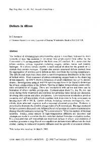
Figure 1: B as Implanted 1.00E+22
-
200eV SiMS 5014
-
200eV Monte Carlo
- - lkeV SIMS le15
i" 1.00E+21 -n"",-...
- - lkeV Monte Carlo
.!!.
s
-200eVVISTA
'"~
-lkeVVISTA
~ 1.00E+20 u
c
o
o
l;
~
o
1.DOE+19
1.00E+18
.L..-_ _-\+'_----"~M&o-_+_----' _
o
0.01
0.02
0.04
0.03
Depth (um)
L-
____"_.&__'
0.05
Monte Carlo simulations have also been performed using the Athena module of the TCAD software produced by SILVACO as well as using the VISTA code[11]. The as implanted SIMS profiles are compared with these simulated results in figure 1. The 1 keV profile is simulated reasonably well all though the shoulder in the profile due to channelled ions is more pronounced in the SILVACO Monte Carlo simulation. The SIMS profile also has a slightly longer tail, which might be due to a room temperature diffusion mechanism as proposed by De La RUbia[12]. The 200 eV SIMS profile again is .Jreasonably well predicted by
both of the Monte Carlo simulations. The SIMS once again shows a much deeper tail than is seen in the simulations. Once again this could possibly be due to a room temperature diffusion mechanism or , possibly, channelling. It is not beyond the possibility that this deep tail is due to a SIMS broadening artefact, although the 10nm per decade broadening needed to produce this slope is much higher than might be expected from normal cascade broadening effects at the low SIMS energy used in this case. The SIMS profiles in this figure are beam at 60" which gives a normal energy component of the from the batch analysed with a 1keV beam of 250eV per oxygen. Estimates of the cascade broadening produced by such a beam using the SUSPRE program[13] suggest the broadening should be no more than 1nm per decade. These effects are more pronounced in the 200 eV profile than the 1 keV profile.
0;
In figure 2 the effects of the 105O"C activation anneal are simulated and compared with the SIMS profile for the 200 eV profile. As the Monte Carlo implant profile did not predict the correct shape the as implanted SIMS profile was used as the input into the activation anneal stage of the simulator, This has the added advantage that any SIMS broadening artefact present in the as implanted results will translate itself to the simulated annealing results making the SIMS and simulation more comparable. We have used the fermi model[14] to simulate the diffusion of the boron. The fermi model is essentially the simplest model for boron diffusion, it ignores all diffusion enhancement effects. If the diffusion
60
models, which take account of the . - - - - - - - - - - - - - - - - - - - - - - - - - - , various enhancement mechanisms normally recognised to exist in the Figure 2: 200eV B Implant after Annealing rapid thermal treatment of boron Comparison with Simulation profiles in silicon, are used then the simulated profile after annealing is 1.00E+20 gOGe anneal much too broad. Even the simple '1 model, neglecting all of the 1000C ann.al E £. 1.00E+19 enhancement effects, predicts a • 1050C anneal much broader profile than is actually observed - as can be seen --SIMS 11.00E+18 in the figure. If, however, the • • g anneal is simulated at a lower 8 effective temperature (a shorter Ci 1.00E+17 time might also be considered) ~ o down to 900OC, a good fit to the 1.00E+16 - 1 - - - - - - + - - - - + - - - -.........--->---_ measured data is obtained.
..:...... ...
.. ... ... ... -. ..
o
0.02
0.04
0.06
0.08
0.1
Similar simulations and measurements have been made for ....- - - - - - - - - - - - - - - - - - - - - - -.... a number of different implant energies all at a dose of 10" ions em-' and it is found that at 500eV the simulated temperature is 970OC, at 1keV it is 1000"C and at 3keV a good fit is found at the correct anneal temperature of 1050°C. This is shown in figure 3. Depth (um)
r - - - - - - - - - - - - - - - - - - - - - - - - - , I t is also possible to simulated many of these effects· particularly FJgure3: B Implants after 1050C Anneal 2QI; with the higher dose implants - by reducing the solid solubility limit of 1.1)0'1+211 • Q.aav BIOOC anneal boron. It is not inconceivable that at --o.a.VSlMS these low energies substantial • Q.5MV B 970C a........ amounts of the implantation has I1.DOE+18 - - o.SIaIVSIMS been made into the native surface • 1kltVB1000c.-..at c oxide of the silicon. In these cases ~° it is quite likely that the boron will i 1.00E+18 • 3kaV B tOSOCannul become complexed and be ~ --3k.VSlMS c:l prevented from diffusion. Figure 4 shows that it is possible to model f u 1.0UE+17 the 200eV 5x10" ions em" results at 1OOOOC by assuming that the solid solubility limit for boron is , 1. reduced by a factor of 3. Figure 5 ..01 "03 "aT "'01 "'3 shows that using the same ~(uml assumption fits are obtained for 900"C and 950°C anneals as well . ....- - - - - - - - - - - - - - - - - - - - - - -.... Similar fits have been obtained for 1keV 10'5 ions em" . In this case the solid solubility limit had to be reduced by only a factor 1.5, but again a good fit is made for all three temperatures.
....
.... .. ..
.. ....
..,.
.."
However, the low dose, 10" ions em", implants and anneals can not be modelled in this way, the concentration of boron is too low to be effected by the solid solubility limit. It should be born in mind, however, that these particular samples were measured with the highest energy SIMS beam, this means that they are victims of the greatest broadening as was evident when comparing the as implanted profiles for the 200eV implants when significant broadening was found. The broader profile will, of course, have a lower apparent surface concentration as area must be conserved. Hence, as the as implanted SIMS profile was used to "seed" the simulation we may well be starting with an artificially
61
reduced surface boron level. By using a more realistic implant profile with a higher surface concentration we may well find that the solid solubility limit dependency in these cases as well. Discussion
Figure 4: 200eV B Implants after 1000e 10s anneal 1.00E+22
- - SIMS proIile - e - - simulated - ssl3
'1 1.00E+21
~ simulated default sa
E
~
........e-- simulated sa/2
~
o
~
!
1.00E+20
~
r~~,:=,""""",,:>oo'OOoc.o.,,-_
o
U
~
:;
o
1.00E+19
1.00E+18
+----+----+--~--'k_____+_--41
o
0.01
0.02
0.03
0.04
0.05
Doptll(um) L-
-l
It should be mentioned that electron and hole trap centres have been detected by Deep Level Transient Spectroscopy in wafers implanted with B at 1 keY and 0.5 keVat a dose of 1x10'·cm-2[2]. The traps are lower, below 10"'cm-3 in the case of the 0.5 keY, by an order of magnitude probably due to the proximity of the surface. The trap concentration is highest close to the end of the Boron implant range. Molecular Dynamics simulation of 0.5 keY boron implants have confirmed that the surface has a strong effect on the recombination of defects generated by implantation which may even be able to migrate at room temperature [12]. There is evidence from comparison with the simulated and measured as implanted profiles that in the 200 eV case some diffusion has taken place prior to the activation anneal, backing up the Molecular Dynamics findings. The surface also seems to provide a sink for the defects reducing the effective diffusivity of the
boron close to the surface. This is evident in that the profile diffusion is inhibited close to the surface. It is possible that this is due to changes in the solid solubility limit of the boron in the surface region, or there may well Figure 5: 200eV B Implants some other factor involved. 1.00E+22
T
- - 5E14 ee ImPanled
--9OOC10s - - e - 950C 10s
'1"
1.00E+21
--0--
1QOOC 10s
~
900C sirTUated
E
~ ~
j
- - e - 950Csimdated
; 1.00E+20 u e
o
U
~
•
U 1.00E+19
1.00E+18 +----+---~_~_'lIlllw.1h__''Ii):>_+_--_j
o
0.02
0.03
0.04
0.05
Doptll (um)
phenomena seen here.
62
The shape of the diffused profile is distorted by comparison to the simulated profile. This could be explained in the same way by assuming that the diffusivity may be more effected closer to the surface. This surface proximity effect will mean that boron close to the surface will diffuse less rapidly than boron deeper into the silicon as the surface has substantially reduced the number of available defects for the boron to diffuse in. Errors associated with SIMS and comparison with the other measurement techniques only suggest that this effect may be stronger than measured here. Clearly, as this is such a surface sensitive effect, the quality of the surface will also have a marked effect on the on the
CONCLUSIONS The xRLEAP implanter has introduced a new enabling technology, key to realising junctions, for 0.25~m and 0.1811m future devices. JunctiOns with depths down to O.04~m have been created by Boron implantation down to 0.2 keV in energy on wafers that received no prior surface treatment or pre-amorphisation using production-worthy beam currents with high current densities. By comparison with computer simulation of both the implantation and the thennal activation process it is evident that there is a diffusion inhibition mechanism acting close to the surface. This adds further support to the suggestions from Molecular Dynamics simulations that the surface allows preferential recombination of defects close by. This may be evident in promoting room temperature diffusion during implantation and inhibiting diffusion dUring the thennal cycle. It is possible that the inhibition dUring the thermal cycle is due to changes in the solid solubility limit of the boron close to the surface. This could be caused by partial implantation into a surface oxide, or just the presence of the surface. The measurements and simulations presented so far are inconclusive into the cause of the effect and further work is underway to enable better understanding of this phenomenon.
REFERENCES [1] National Technology Roodmap for Semiconductors, Semiconductor IndUstry Association, San Jose, Cal 1994. [2] M Foad, J England, S Moffatt and 0 Annour, "Analysis of sub- 1 keV Implants in Silicon using SIMS, SRP, MEISS and OLTS: The xRLEAP Low Energy, High Current Implanter Evaluated", Presented in the Ion Implantation Technology-96, Austin Tx June 1996. [3] J. England, L. Joyce, C. Burgess, S. Moffatt, M. Food, O. Annour, and M. Current, "The Applied Materials xRLEAP ion implanter for ultra shallow junction formation", Presented in the Ion Implantation Technology-96, Austin Tx June 1996. [4] KBeardmore, O.Cai, N.Gronbech-Jensen, "Molecular Dynamics Simulation of Low Enery Boron and Arsenic Implant into Silicon", to be published 1996 [5] SAPrussin, "Modelling the Efect of Channelling", to be published 1996 [6] M J Caturia and T Oiaz de la Rubia, presented at MRS fall meeting, Dec.'96.
[7] L. Kaabi, C. Gontrand, B. Remaki, F. Seigneur, and B. Balland, " Analysis of low energy implants in silicon through Si02 films: implantation damage and anomalous diffusion: J. Microelectronics, vol 25, pp.567-5761994. [8] S. Prussin, and P. F. Zhang, "A physical model for the role of dose and the dose rate on amorphous depth generation", Presented in the Ion Implantation Technology-96, Austin Tx June 1996. [9] S. Smith, V. K. Chia, and M. H. Yang," Ion implaner diagnostics using SurfaceSIMS", Presented in the Ion Implanation Technology-96, Austin, Tx June 1996. [10] M.Food, RP.Webb, RM.Gwilliam, A.P.Knights and G.Thomas, presented at the "Ultra Shallow Junctions Meeting, North Carolina, April 1997. [11] VISTA Monte Cario program curtosey of Alexander Burenkov [12] M J Caturia and T Oiaz de la Rubia, presented at MRS fall meeting, Dec.'96. [13] RP.Webb, Appendix 3 in "Particle Beam Analysis" Vol 2, Eds. M.Seah and O.Briggs, 1992 [14] Silvaco Athena Users Manual, Chapter 3, October 1996.
63