1
Deferred Pixel Shading on the PLAYSTATION®3 Alan Heirich and Louis Bavoil
Abstract— This paper studies a deferred pixel shading algorithm implemented on a Cell/B.E.-based computer entertainment system. The pixel shader runs on the Synergistic Processing Elements (SPEs) of the Cell/B.E. and works concurrently with the GPU to render images. The system's unified memory architecture allows the Cell/B.E. and GPU to exchange data through shared textures. The SPEs use the Cell/B.E. DMA list capability to gather irregular fine-grained fragments of texture data generated by the GPU. They return resultant shadow textures the same way. The shading computation ran at up to 85 Hz at HDTV 720p resolution on 5 SPEs and generated 30.72 gigaops of performance. This is comparable to the performance of the algorithm running on a state of the art high end GPU. These results indicate that the Cell/B.E. can effectively enhance the throughput of a GPU in this hybrid system by alleviating the pixel shading bottleneck. Index Terms—Computer Graphics, HDTV, Parallel Algorithms, Rendering
I. INTRODUCTION
T
he current trend toward multi-core microprocessor architectures has led to performance gains that exceed the predictions of Moore's law. Multiple cores first became prevalent as fragment processors in graphics processing units (GPUs). More recently the CPUs for computer entertainment systems and desktop systems have embraced this trend. In particular the Cell/B.E. processor developed jointly by IBM, Sony and Toshiba contains up to nine processor cores with a high concentration of floating point performance per chip unit area. We have explored the potential of the Cell/B.E. for accelerating graphical operations in the PLAYSTATION®3 computer entertainment system. This system combines the Cell/B.E. with a state of the art GPU in a unified memory architecture. In this architecture both devices share access to system memory and to graphics memory. As a result they can share data and processing tasks. We explored moving pixel shader computations from the GPU to the Cell/B.E. to create a hybrid real time rendering system.
Alan Heirich is with the Research and Development department of Sony Computer Entertainment America, Foster City, California. Louis Bavoil is with Sony Computer Entertainment America R&D and the University of Utah, School of Computing, Salt Lake City, UT (e-mail:
[email protected]).
Our initial results are encouraging and we find benefits from the higher clock rate of the Cell/B.E. and the more flexible programming model. We chose an extreme test case that stresses the memory subsystem and generates a significant amount of DMA waiting. Despite this waiting the algorithm scaled efficiently with speedup of 4.33 on 5 SPEs. This indicates the Cell/B.E. can be effective in speeding up this sort of irregular fine-grained shader. These results would carry over to less extreme shaders that have more regular data access patterns. The next two sections of this paper introduces the graphical problems we are solving and describe related work. We next describe the architecture of the computer entertainment system under study and performance measurements of the pixel shader. We study the performance of that shader on a test image and compare it to the performance of a high-end state of the art desktop GPU, the NVIDIA GeForce 7800 GTX. Our results show the delivered performance of the Cell/B.E. and GPU were similar even though we were only using a subset of the Cell/B.E. SPEs. We finish with some concluding remarks. II. PIXEL SHADING ALGORITHMS We study variations of a Cone Culled Soft Shadow algorithm [3]. This algorithm belongs to a class of algorithms known as shadow mapping algorithms [15]. We first review the basic algorithm then describe some variations. A. Soft Shadows Soft shadows are an integral part of computing global illumination solutions. Equation (1) describes an image with soft shadows in which, for every pixel, the irradiance L arriving at a visible surface point from an area light source is
L=
∫E
Ω light
light
⎡ cos θ l cos θ i ⎤ ⎢ ⎥VdΩ πr 2 ⎣ ⎦
(1)
In this equation Ωlight is the surface of the area light and dΩ is the differential of surface area. Elight is the light emissivity per unit area, and θl , θi are the angles of exitance and incidence of a ray of length r that connects the light to the surface point. V is the geometric visibility along this ray, either one or zero. The distance term 1 / π r2 reflects the reduction in subtended solid angle that occurs with increasing distance. This expression assumes that the material surface is diffuse (Lambertian).
Deferred Pixel Shading on the PLAYSTATION®3
2
When V=1 and Ωlight has area dΩ this equation describes diffuse local illumination from a point light as is typically computed by GPUs using rasterization. When this equation is expanded recursively in E (by treating each surface point as a source of reflected light) the result is a restriction of the Rendering Equation of global illumination [12] to diffuse surfaces. B. Cone Culled Soft Shadows Equation (1) is traditionally solved by offline methods like ray tracing. Stochastic ray tracing samples the integrand at various points on Ω and accumulates the result into L. The CCSS algorithm takes an analogous approach, rendering from the light and gathering the radiance from the resulting fragments into pixels. The CCSS algorithm consists of fragment generation steps and a pixel shading step. We have implemented fragment generation on the GPU and pixel shading on the Cell/B.E. The GPU is programmed in OpenGL-ES using Cg version 1.4 for shaders. Fragments are rendering into OpenGL-ES Framebuffer Object texture attachments using one or more render targets. These textures are then detached from the Framebuffer Objects and used as input to the pixel shading step. The pixel shading step returns a shadow texture which is then bound to the GPU for final rendering. The algorithm is not physically correct and we accept many approximations for the sake of real time performance. Lights are assumed to be spherical which simplifies the gathering step. Light fragments for each pixel are culled against conical frusta rooted at the pixel centroid. These frusta introduce geometric distortions due to their mismatch with the actual light frustum. The culling step uses one square root and two divisions per pixel. No acceleration structure is used so the algorithm is fully dynamic and requires no preprocessing. The algorithm produces high quality shadows. It renders self-shadowed objects more robustly than conventional shadow mapping without requiring a depth bias or other parameters. 1) Eye Render The first fragment generation step captures the locations of pixel centroids in world space. This is done by rendering from the eye view using a simple fragment shader that captures transformed x, y and z for each pixel. We capture z rather than obtaining it from the Z buffer in order to avoid imprecision problems that can produce artifacts. We use the depth buffer in the conventional way for fragment visibility determination. If this is used as a base renderer (in addition to rendering shadows) then the first step also captures a shaded unshadowed color image. This unshadowed image will later be combined with the shadow texture to produce a shadowed
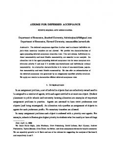
final image. For some shaders, such as approximate indirect illumination, this step can also capture the surface normal vectors at the pixel location. 2) Light Render The second fragment generation step captures the locations and alpha values (transparency) of fragments seen from the light. For each light, for each shadow frustum, the scene is rendered using the depth buffer to capture the first visible fragments. The positions and alphas of the fragments are generated by letting the rasterizer interpolate the original vertex attributes. For some shaders, including colored shadows and approximate indirect illumination, this step also captures fragment colors. 3) Pixel Shading In the third step, performed on the Cell/B.E., light fragments are gathered to pixels for shading. Pixels are represented in an HDTV resolution RGBA texture that holds (x,y,z) and a background flag for each pixel. Light fragments are contained in one (or more) square textures. Pixel shading proceeds in three steps: gathering the kernel of fragments for culling; culling these fragments against a conical frustum; and finally computing a shadow value from those fragments that survived culling. 4) Fragment Gather For each pixel, for each light, the pixel location (x,y,z) is projected into the light view (x',y',z'). A kernel of fragments surrounding location (x',y',0) in the light texture is gathered for input to the culling step. Figure 1 illustrates this projection and the surrounding kernel. It is not necessary to sample every location in the kernel, and performance gains can be realized by subsampling strategies. In our present work we are focused on system throughput and so we use a brute-force computation over the entire kernel. 5) Cone Culling For each pixel, for each light, a conical frustum is constructed tangent to the spherical light with its apex at the pixel centroid as illustrated in figure 2. The gathered fragments are tested for inclusion in the frustum using an efficient point-in-cone test. The point-in-cone test performs these computations at each pixel: axis alength
= =
light.centroid – pixel.centroid axis . axis
=
alength2 alength2)
2
cos2θ
Deferred Pixel Shading on the PLAYSTATION®3
/
(light.radius2
+
3 na
=
normalize(axis) 6) Computing new shadow values The final step is to compute shadow values from the fragments that survived the culling step. Here we describe three such shading computations, and others are possible. We present detailed performance measurements of the monochromatic shader in section 5. We have implemented substantial portions of the other shaders on the Cell/B.E. and GPU to verify proof-of-concept. a)
Figure 1 (kernel lookup). The pixel is projected from the world into the light plane, which is equivalent to finding the nearest fragment F in the light view to the ray from the pixel to the light center. In this example fragment F blocks the ray from the light to the pixel, and we say F shadows the pixel.
Monochromatic soft shadows
We can compute monochromatic soft shadows from translucent surfaces by using a generalization of the Percentage Closer Filtering algorithm [14]. Among the fragments that survived cone culling we compute the mean alpha (transparency) value. The resulting shadow factor is one minus this mean. At pixels where no fragments survived culling the shadow factor is one. Test images for this shader appear in figure 3. b)
Colored soft shadows
We can obtain colored shadows by including the colors of the translucent fragments and of the light source. In addition to computing the mean alpha value we also compute the mean RGB for the fragments. This requires gathering twice as much fragment data for the shading computation. We multiply these quantities with the light source color to obtain a colored shadow factor. At pixels where no fragments survived culling the shadow factor is one. c)
Figure 2 (cone culling). Computing the shadow intensity at a pixel in a cone with the apex at the pixel and tangent to the light sphere. The fragments of the light view are fetched in a kernel centered at the projection of the cone axis over the light plane. Fragments are tested for visibility using an efficient point-in-cone test+. The point-in-cone then performs these computations for each fragment: fe
=
axisDotFe direction flength2 inside pointInCon e
= = = = =
fragment.centroid – pixel.centroid na . fe (axisDotFe > 0) fe . fe (cos2θ * flength2