Amisaki, E. Hashimoto, H. Ikeda, A. Kusumi, N. Miyakawa, "Development of MD Engine: high-speed accelerator with parallel processor design for molecular.
DEM-1: A Particle Simulation Machine for Efficient Short-range Interaction Computations Ryo Takata Graduate School of Information Systems University of Electro-communications 1-5-1, Chofugaoka, Chofu, Tokyo, Japan Image Technology Laboratory Corp. 3-36-19, Tamagawa, Chofu, Tokyo, Japan takata @yuba.is.uec.ac.jp Abstract This paper describes the architecture of high performance, particle simulation machine, DEM-1 for short-range particle interaction computations. All existing particle simulation machines have specialized pipelines to calculate long-range particle interactions effectively. However, their ability to perform particle simulations efficiently diminishes with short-range interactions. The communication cost component of particle simulations will play a significant role in performance when the computation cost becomes O(N). DEM-1's three dimensional torus high-speed network reduces the communication cost while 2048 local processors perform the time integration. The elimination of pipeline bubbles in DEM-1 is achieved by specially designed cut off judgment units. Each specialized pipeline consists of dedicated data path supported by position vector prefetch dual ported memory. The performance of DEM-1 will be presented with very large-scale Embedded Atom Method (EAM) molecular dynamics simulations.
1. Introduction Particle simulation has been widely used in various fields such as astrophysics, molecular dynamics, gas-solid flows, and computer graphics. These simulations can be executed in parallel, because most of the computation time is spent on the calculation of interactions that can be evaluated simultaneously. The machine GRAPE[1] has been developed to reduce the execution time of largescale astrophysical simulations. The machines MD GRAPE[2], MD One[3], MD Engine[4], and MDM[5] have been developed to reduce the execution time of molecular dynamic simulations of protein and other particle simulations. These parallel particle simulation machines have specialized parallel hardware pipeline to
Kenji Kise, Hiroki Honda, Toshitsugu Yuba Graduate School of Information Systems University of Electro-communications 1-5-1, Chofugaoka, Chofu, Tokyo, Japan {kis, honda, yuba}@yuba.is.uec.ac.jp
calculate the arbitrary central force and hence to increase the performance. In certain particle simulations, shortrange cut-off interactions dominate the system behavior. Molecular dynamics simulation of metallic solids with Embedded Atom Method (EAM) falls into this category of computations. It is difficult to perform these simulations efficiently on the available particle simulation machines because they are not optimized to perform such short-range interactions. Here, we propose a particle simulation machine DEM1 optimized for such applications. Section 2 describes the background and motivation. Section 3 focuses on the architectural details of DEM-1. Section 4 summarizes the performance of DEM-1. Section 5 summarizes related work.
2. Background and motivation 2.1 Sample application Embedded Atom Method (EAM) [6] is widely used in molecular dynamics simulations of metallic solids. In EAM, the potential energy is calculated by using the following formula. 1 (1) E tot = ∑ Fi (ρ h ,i ) + ∑ φ ij (rij ) 2 i, j i The force exerted onto atom i is represented by r r (2) f = − (F ′(ρ )ρ′ (r ) + F ′(ρ )ρ′ (r ) + φ′(r ))r i
∑
j ( ≠i )
i
a
ij
j
a
ij
ij
ij
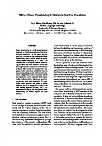
For example, consider the simulation of BCC iron. The cut off radius for such computation is 3.64A. Typically 4 particles exist inside a cell. So approximately 100 particles have a chance to interact with the target particle in linked-cell-list method. However, only 10-20 particles actually exert force on the target particle. The simulation parameters of the computation vary according to the dimensions of the target system and the objective of the simulation. Radiation damage simulation
0-7695-1573-8/02/$17.00 (C) 2002 IEEE
of iron requires more than one million atoms and 10 thousand steps. Creep or crack growth simulations need over 100 million atoms. In EAM simulations with a particle simulation machine, two potentials (ρ,Φ) and two forces (ρ',Φ') are calculated by hardware pipeline, while F'(ρ) calculation or time step integration such as particle position vector updates are done by the host computer.
"rough" cut off sphere cut off sphere
ith particle
neighboring cells
2.2 Performance bottleneck The performance of MD One particle simulation machine[3] was analyzed with a model; Tstep = T pre + Tw + Tcalc + Tr + Tother + Tmove + Tovh
(3)
where Tstep is overall time required for a step, Tpre is initialization time of MD One, Tw is transfer time of position vectors and coefficients, Tcalc is pipeline calculation time (including target particle position vector write time), Tr is result read time, Tother is other calculation time of bond interactions or center of mass velocity correction, etc., Tmove is position vectors, velocities, etc. update time, and Tovh is other overheads such as logging in, respectively. All existing particle simulation machines assume that the calculation time dominates the total performance. Tcalc >> T pre + Tw + Tr + Tother + Tmove + Tovh
(4)
This may be true for the simulations with interactions whose calculation costs are O(N2) or O(N1.5). Here N is the number of particles in the system. In the case of Lennard-Jones interactions the calculation cost O(N) is significant. Therefore, it is possible to discuss them on the same basis. However, it is important to note that even with O(N2) computations, the effective performance can rapidly decrease with the increase of number of boards. In many molecular dynamics applications such as EAM, the calculation cost of interactions is O(N) and the effect of other terms cannot be neglected. Most of these costs can be attributed to: (1) communication time between host computer and hardware pipelines, (2) execution time of calculations related to the portion of simulations other than the interaction calculation. In addition to these bottlenecks, most of the existing particle simulation machines have inefficient pipeline for computations related to particle pairs encountered in linked-cell-list method particle search. The pipeline requires approximately 13 times many operations than software calculations (see Figure 1 and Appendix A). This reduces the effective performance of existing particle simulation machines by one order. The original GRAPE was targeted to astrophysical simulations where gravitational forces are calculated with no cut off. It appears that the GRAPE family members inherit its
Figure 1. Linked-cell-list method and cut off sphere (2 dimensional view) architecture with no performance improvement. MDEngine [4] has facility to utilize generated pair list without software overhead, but its performance improvement factor did not exceed 2. Thus, it is possible to achieve another performance improvement of 6.5.
3. Architecture of DEM-1 3.1 Design policy DEM-1 consists of communicating microelements; each integrates 4 MIPS microprocessors, 4 hardware pipelines and link interface along with external memory. Eight elements are connected together to create a higherlevel structure. Thus, three levels of integrations are defined in DEM-1 system configurations. These higherlevel elements always have faster interconnection speed than the lower level elements. DEM-1 has threedimensional torus network on its top level and the simulation space can be mapped on to it spatially. The processors, that are located adjacent to the hardware pipelines, work in parallel to accelerate O(N) tasks such as time integration. In addition to that, existence of local processors makes the local time step integration possible and hence resulting in great communication cost reduction. DEM-1 is equipped with specialized pipelines to calculate short-range interactions of particles. Even though the calculation cost is only O(N), each potential or force calculations requires as many as 30 arithmetic operations. More than 90% of the total computation time consists of such computations. Therefore, it is possible to accelerate it by parallel hardware pipelines, as it is with existing particle simulation machines. Naturally, care should be taken not to block operations by external and/or internal bus bottleneck when designing the pipeline. DEM-1 integrates dual ported memory and pre-fetches position vectors (and coefficients) of the interacting particles. To eliminate the pipeline bubble, we introduce multiple cut off judgement units before its main pipeline. DEM-1 will be provided to users in three configurations:
0-7695-1573-8/02/$17.00 (C) 2002 IEEE
Table 1. Three configurations of DEM-1
MIPS CPU DEM pipeline
MIPS CPU
Configuration pipelines processors Board 32 32 Node 256 256 Cluster 2048 2048
perfromance (Gflops) 115.2 921.6 7,373
memories link speed link (Gbytes) (Mbytes/sec) interface 2 133*6 LVDS 16 1000*3 RHiNET2 128 (2000) RHiNET2
DEM pipeline DEM pipeline DEM pipeline
DEM Node
DEM Board
DEM Board
DEM Chip & Memory
RHiNET-2/SW
DEM Node
DEM Board
DEM Chip & Memory
DEM Board
DEM Chip & Memory
DEM Node DEM Board DEM Node DEM Board
RHiNET-2/SW
DEM Chip & Memory
DEM Board
DEM Chip & Memory
DEM Board
DEM Chip & Memory
DEM Node RHiNET-2/SW
DEM Node
DEM Node RHiNET-2/SW
RHiNET2 NIC
Cache(I/D)
Local BUS
Link Interface
North Sounth East
MIPS CPU
Cache(I/D)
Local BUS
West
Global Bus(256bit)
Figure 3. DEM-chip block diagram
DEM Chip & Memory
DEM Board
DEM Node
Up Down
OnChipMemory 2Mbyte DRAM
DEM Cluster(TOP)
DEM Node
Cache(I/D)
Local BUS MIPS CPU
Memory Controller
Cache(I/D)
Local BUS
DEM Chip & Memory
RHiNET2 NIC
6 channel Channel Link Interface
RHiNET2 NIC
64bit,66MHz PCI
Figure 2. Structure of DEM-1 system 1) A Compact PCI add-on board. 2) A node of up to 8 DEM-1 boards. 3) A cluster consists of up to 8 DEM-1 nodes. System specifications of DEM-1 are listed in Table 1. Figure 2 describes these three different configurations and their hierarchical connections. By adding one DEM-1 board to a PC, particle simulations can reach with performance over 100Gflops. A DEM-1 node in a 6U system rack arrangement could provide 1Tflopscomputing speed by the side of the desk. The DEM pipelined processor Chip is designed to achieve the goals outlined above. The DEM pipeline is upward compatible with MD-GRAPE chip[2] and can calculate arbitrary central forces. Therefore, DEM-1 should be able to execute most of the particle simulations running on MD-GRAPE or MD One[3] such as molecular dynamics simulations of proteins. A DEM Chip integrates 4 pipelines and 4 processors to have 14.4Gflops effective performance.
3.2 Detailed design DEM-Cluster A DEM-Cluster consists of 8 DEMnodes connected via 3 RHiNET2-SW[7]. Each node can communicate 3 contacting nodes with approximately
1Gbyte/sec speed in parallel. Additional RHiNET2-SW connects the cluster to external network. DEM-Node Up to 8 DEM-boards are tightly connected to make a DEM-node. The node has maximum of three RHiNET2 NICs to communicate with other computers/storages or DEM-nodes. DEM-Board A DEM-board integrates 8 DEM-chips, particle memories connected to each DEM-chip, a switchFPGA with 6 channel-link interface transceivers and a 64bit, 66MHz PCI interface. A DEM-board has 115.2Gflops performance and memories that can hold 8,000,000 particles. PCI interface is used to communicate with host CPU in single board configuration. Up to 256Mbytes of DDR FCRAM attached to each DEM-chip is used to store position vectors, velocities, accelerations, derivative of accelerations, coefficients and linked-celllists. Six LVDS channel-link interfaces connected to switch FPGA have 133 Mbytes transfer rate to each channel and direction. DEM-Chip Figure 3 shows the block diagram of the DEM-Chip. The DEM- chip integrates four hardware pipelines with dedicated on chip processors and cache memories, memory controller, which handles linked-celllist addressing, on chip DRAM memory and local link interface in a single LSI. The 8 bytes wide memory bus of DEM-Chip can transfer 16 bytes per main CLK cycle with its DDR FCRAM interface. DEM-Pipeline Block diagram of DEM-pipeline is shown in Figure 4. The design of DEM pipeline is based on the MD GRAPE CHIP[2] with 2 major enhancements: (1) Cut off judgement unit, (2) position vector pre-fetch dual ported memory.
0-7695-1573-8/02/$17.00 (C) 2002 IEEE
Cut Off Judgement Unit Dual Ported Memory
φ' = φ'(r2)r
Dual Ported Memory
ρ' =
Force Accumlator
Σφ'kj
(Fk,l +Fi)ρ'(r2)r
Post rlj if | rlj | < rcut
Xi 40 40 Xj 40 Xij= Xi-Xj
Function Table ρ'
Σρ'lj Force Accumlator
Σφ'lj
average0.5 / clock
8
Xij2
0.5 / clock
1 / clock
Zij
15 16 Xij2+ Yij2
Yi 40
40 extract middle bits
Yj 40 Yij= Yi-yj
8
Yij2
16 rij2=X ij 2+ Yij2+Z ij2
15
FIFO-WE 16
RCUTSQ
rij2 > RCUTSQ
Zi 40 40
0.08 / clock
extract middle bits
Force Accumlator Function Table φ'
Yij
Delay r ij
Σρ'kj
Main Pipeline
FIFO Cut Off Judgement Unit
Xij
Force Accumlator
Post rkj if | rkj | < rcut
Zj 40 Z = ij Zi-Z j
extract middle bits
8
Zij 2
15
Delay 15
POINT
Peak 4 / clock Effective 3.2 / clock
Figure 5. Block diagram of cut off judgement unit
Figure 4. DEM-Pipeline block diagram Note: the Width of each arrow corresponds to the pipeline data rates.
Cut Off Judgement unit #1
rk1 rk2 rk3 rk4 rk5 rk6 rk7 rk8 rk9 rk10 rk11 rk12 rk13 rk14 rk15 rk16 rk17 rk18
Cut Off Judegment unit #2
rl1 rl2 rl3 rl4 rl5 rl6 rl7 rl8 rl9 rl10 rl11 rl12 rl13 rl14 rl15 rl16 rl17 rl18
Cut Off FIFO #1 Write
3.3 Pipeline operations Two cut off judgment units use reduced accuracy and fixed point arithmetic. The reduced accuracy results in a slight loss in efficiency. Because of this imprecise arithmetic several particles actually lying outside of the cut off sphere may pass through the unit (see "rough cut off sphere" in Figure 1). However, this improves the performance and hardware resource utilization. The frequency of two cut off judgement units is two times the frequency of the main pipeline. These units eliminate the bubbles in main pipeline and increase the effective performance of the entire pipeline by a factor of four. Hardware resources required for the cut off judgement units are estimated to be less than 10% of the total pipeline. In addition, main pipeline can calculate two interactions of a particle pair alternatively, for the pipeline with two function tables. Figure 5 shows detailed block diagram of cut off judgement unit. In DEM system, coordinates are converted to 40bit signed fixed point format and then stored in memory. Fixed-point 40bit subtractions are performed to obtain relative distance vector between particles i and j. Obtained relative distance is represented also in 40 bit fixed point format but their maximum absolute values are limited to twice of unit cell size, because particles i and j are contained within the neighboring cells. Therefore we can drop certain upper bits without any problems. Also, we drop lower bits for we allow less accuracy in rough cut off judgement. In current design, we extract 8 bits signed integer to calculate rough squared distance between particle ij. The extract point depends on the simulation conditions (i.e.
Cut Off FIFO #2 Write Cut Off FIFO #1,2 Read
rk11
rl1 rl2
rl11
rl1
Function Generator Out Put
ρ(rl1)
rl22
rk11
rl2
φ(rl1)
ρ(rl2)
φ(rl2) bubble ρ(rk11) φ(rk11)
Accumlator (1,ρ)
ρ(rk11)
Accumlator (1,φ) Accumlator (2,ρ)
ρ(rl1)
Accumlator (2,φ)
ρ(rl2) φ(rl1)
φ(rl2)
Figure 6. Pipeline timing
system size and unit cell size), so that it is made possible to adjust extract point parameter (POINT) by software. Cut off radius, RCUTSQ, used in the final comparator stage is also programmed by software. The programmer is expected to take account of the errors introduced by the imprecise arithmetic when he determines RCUTSQ. Pipeline operation timing is shown in figure 6. Note that two cut off judgement units run in double frequency. In the example shown in Figure 6, cut off judgement unit #2 finds two neighboring particle pairs (rl1, rl2) and put them into cut off FIFO #2. Then main pipeline reads relative distance vector rl1 form cut off FIFO #2 to calculate ρ and φ sequentially. Pipeline controller selects
0-7695-1573-8/02/$17.00 (C) 2002 IEEE
Table 2. Pre-fetch DPM design number of interactions number of particles in a cell neighboring cells number of pipelines number of neighboring partilces number of interacting particles bytes par particle object cell size object particles * clocks per particle clocks to calcluate object cell(s) * cells reqired * particles reqired * bytes required * bytes per clock to fill DPM size of a DPM number of xy planes in DPM
symbols equations Ni Npc Nn 3^3 Npipe Nnp Npc*Nn Nip Nbpp Lcell (strategy) Npz Lcell^2*Npc Nclk Nip*Ni/Npipe Nzck Npz*Nclk Nzcell (Lcell+2)^2 Nscz Nzcell*Npc Nbr Nscz*Nbpp Nbpc Nbr/Nzck Nbytes 16384 Nzpl Nbytes/Npz
case#1 2 4 27 4 108 16.8 20 1 4 8.4 33.5 9 36 720 21.5 16384 22.8
Object cells
X axis case#2 2 4 27 4 108 16.8 20 4 64 8.4 536.6 36 144 2880 5.4 16384 5.7
case#3 2 8 27 4 216 33.5 20 2 32 16.8 536.6 16 128 2560 4.8 16384 6.4
Pre-fetching cells Object particle search direction
Z axis Case #1 Object cells
X axis
Required cells
Pre-fetching cells
Object particle search direction
All values with (*) are listed per xy plane.
accumulator(2, ρ) and accumulator(2, φ) respectively to accumulate these results. Next, particle pair l2 is calculated in the same manner. During main pipeline calculation, two cut off judgement pipelines are busy checking for next candidate particle pairs but failed to find any. Cut off FIFOs become empty and main pipeline executes a bubble cycle, which does not affect any accumulators. Then cut off judgement unit #1 and #2 find particle pairs rk10 and rl10 to be inside cut off sphere. Main pipeline resumes effective cycle that updates accumulator(1, ρ). Cut off judgement unit halts when it detects that the corresponding cut off FIFO becomes full. Unlike other particle simulation machines, DEM-1 has dedicated data flow path to each pipeline. This feature eliminates pipeline overhead introduced by pipeline data sharing and increases effective performance. This "data sharing overhead" will be discussed in section 5 in detail. DEM chip have eight 16Kbytes position vector prefetch dual ported memories. Usually, data have been written to these 8 DPMs by broadcast. In others words, they have copies of each other. However, their reads can occur independently. Position vectors and coefficients are used many times repeatedly during the pipeline calculation. Thus it is possible to pre-fetch them via relatively slower external bus without reducing the pipeline performance. External bus bandwidth required to keep internal pipelines running busy depends on the size of the dual ported memory and pre-fetch strategy. Table 2 and figure 7 show some typical cases of pre-fetch strategies. The memory controller of DEM-Chip prefetches particle along z axis. In case#1, a single column of cells and surrounding cells are read into pre-fetch dual ported memory. The case requires 21.5 bytes/clock transfer rate, which is higher than 16 bytes/clock peak transfer rate of DEM-Chip external memory bus. On the other hand, only 5.4 bytes/clock transfer rate is sufficient
Required cells
Z axis Case #2
Figure 7. Pre-fetch strategies (2 dimensional view)
in case#2 in which 4x4 columns of cells are calculated at a time. The number of xy planes contained in 16K bytes is 5.7. Note that the minimum number of xy planes is 4 considering overlapped pre-fetch during pipeline calculations. Number of average particles, which are contained in a cell, may increase depending on the interactions we adopt. We can adjust "object cell size" (Lcell) parameter to get optimum transfer rate (Nbpc) and number of xy planes in DPM (Nzpl). Case#3 shown in Table 3, in which number of particles within a cell (Npc) equals to 8, describes such a situation.
4. Performance 4.1 EAM simulations on DEM-1 DEM-1 executes EAM simulation as the following . (1) Load initial coordinates and velocities to every node. (2) Communication interface units exchange neighboring cells between chips, boards and nodes. (3) DEM pipelines calculate ρ and φ
0-7695-1573-8/02/$17.00 (C) 2002 IEEE
Table 3. Estimated pipeline performance
number of interactions number of particles in a cell number of pipelines cells par chip neighboring cells number of neighboring particles number of interacting particles clocks per particle total clocks total time(msec)
symbols Ni Npc Npipe Nc Nn Nnp Nip Nclk Ntc Tt
equations
64^3 Nn*Np Ni/6.44 Nip*Ni Nc*Nclk/Npipe Ntc/133M*1000
Table 4. Estimated communication time
numbers 4 4 4 262144 27 108 16.8 67.1 4396204 33.1
(4) Embedded processors calculate F'(ρ), (5) Communication interface units exchange F'(ρ) of neighboring cells between chips, boards and nodes. (6) DEM pipelines calculate ρ' and φ'. (7) Embedded processors update coordinates, velocities etc. (8) Communication interface units exchange moving particles betweenchips , boards and nodes. (9) Back to step (2) and repeats until simulation completes. Snap shots may be sent via RHiNET for logging in with certain intervals (may not every step).
4.2 Performance estimation The DEM-1 is capable of solving 512M particle system EAM simulations. Each element, ranging form DEM-pipeline to DEM-node, calculates their spatial region in less than 1sec and the high-speed links can exchange surface particles and coefficients within that computation time. The performance of DEM-1 depends on the performance of its hardware pipeline. As described in Figure 4, the pipeline executes 4 cut off judgement operations per main clock cycle time, while 0.5 particle pair is fed through the main pipeline, which calculates 2 interactions on the same particle pair within 2 clock cycles ("multiple simultaneous interactions " mode). Therefore, total effective operation of the DEM pipeline is represented by;
N op = 4 ∗ Reffcju ∗ N cju + N main
(5)
where Nop is the total operations of the pipeline per clock, Reffcju is efficiency of cut off judgement unit, Ncju is number of operations of cut off judgement unit, Nmain is number of operations of the main pipeline, respectively. Efficiency of the cut off judgement unit is limited by the ratio Reff (see Appendix A):
particles cells surface cells surface particles transfer bytes link speed(bytes/sec) required time(msec)
system 512M 512^3 1.5M 6M N.A. N.A. N.A.
node 64M 256^3 384K 1.5M 120M 3G 40
4 * Reffcju ≤ 0.5 ∗ Reff
board 8M 128^3 96K 384K 30.7M 800M 38.4
chip 1M 64^3 24K 96K 7.7M 400M 19.2
(6)
This leads to Reffcju = 0.81, which denotes that cut off judgement units should idle sometimes. If we assume Ncju = 9 and Nmain = 21 (we omit operations of squared distance calculation in Nmain because it has been already counted in Ncju), the overall performance is estimated to be 50(= 4*0.81*9+21). We should count the nonvectorized nature of the hardware pipeline (see also Appendix A). The effective performance of the pipeline is 25 operations per clock. This corresponds to 3.33Gflops with 133MHz clock. The MIPS processor attached to the pipeline is 266Mflops. We expect approximately 14.4G flops performance with four pipelines and four processors. Estimated pipeline performance is shown in Table 3. A DEM chip has 4 dedicated pipelines to calculate interactions, which run in 133MHz system clock. By filtering out particle pairs laying outside of the cut off sphere with cut off judgement units, the main pipeline works with it maximum efficiency, so that it takes only 67 clocks to calculate 4 interactions required in EAM simulations. We estimate 33msec execution time for 1M particle interaction calculations by a DEM-pipeline. Times required to exchange particles are estimated in Table 4. DEM chips, boards, or nodes exchange 160 bits(120bits coordinates, 32 bits F'(ρ) and 8 bits tag) per each particles existing inside surface cells. We roughly estimate transfer bytes of moving particles, which have more bytes but less in numbers, to be roughly equal to the former. Together, we assumed 40 bytes/particle are transferred during a time step of EAM simulation. As seen in Table 4, DEM system can exchange particles within 40msec par time step when it executes 512M particles bulk iron simulation. We have not fully investigated the time required for 1time-step integration, which depends strongly on the performance of embedded processors.
5. Related work MD GRAPE[2] is developed at University of Tokyo along with its commercial version MD One[3]. Both of
0-7695-1573-8/02/$17.00 (C) 2002 IEEE
Common Pipeline BUS MD CHIP #0 r0-r5
UNION of neighboring cells(3x3x(6+2))
Table 5. Particle simulation machines
MD CHIP #1
MD CHIP #2
MD CHIP #3
r6-r11
r12-r17
r18-r23
Reg write via CPU BUS
r0,r1 r2,r3
r4,r5 r8,r9 r12,r13 r16,r17 r20,r21 r6,r7 r10,r11 r14,r15 r18,r19 r22,r23
Figure 8. Pipeline overhead introduced by data sharing (2 dimensional view)
them have linked-cell-list addressing support hardware, and neighbor list FIFO that stores indices of particles falling inside the cut off sphere. A single host processor controls multiple boards with multiple pipelines, which share common data path within the board. MD Engine[4], developed at Fuji Xerox corp., has similar single host processor system architecture but has a special purpose circuit for utilizing the neighbor list. It reduces the calculation cost by 50% under certain conditions. MDM[5] is a very large-scale and high speed version of MD GRAPE with dedicated wave number space part accelerator WINE-2. MDM has 4 nodes of 6-cpu parallel host computers running MPI. However, its basic architecture is not much different from that of MD GRAPE. Therefore, most of the deficiencies discussed in earlier sections of this paper exist and reduces the performance when it executes particle simulations with short-range interactions. Both MDM[5] and MD GRAPE[2] have identical memory architecture in which pipelines share the same memory data fed to the pipelines. They also have virtual multiple pipelines at chip level to reduce external bus bandwidth without sacrificing pipeline performance in simulations without cut off. However, if we execute simulations with short-range interactions, their performance is limited by pipeline data sharing. For example, let us consider running an EAM simulation of iron on MD-GRAPE. As we have seen before, typically only 4 particles are contained in a cell. In MD-GRAPE system, 4 chips with 6 virtual multiple pipelines (total 24 pipelines) share a single memory data path. That means, up to 6 cells may be calculated simultaneously. The common pipeline bus feeds particles that fall within union of neighboring cells, which contain approximately 8/3 particles compared to calculations without this overhead. This is described in figure 8. DEM-1's dedicated data path
Developed at Short range interactions Pipeline data path Cut off judgement Linked cell list generation pipelines/LSI processors/LSI operations of pipeline/clock(#1) pipeline speed processors/system Location of processor(s)
MD GRAPE[2]
MD Engine[4]
University of Tokyo
Fuji Xerox Co., Ltd.
MDM[5]
Riken
DEM-1 University of ElectoCommunications
Not optimized Shared Generates pair list
Not optimized Shared Utilizes pair lis t
Not optimized Shared Generates pair list
Optimized independent controls pipeline
software 1 0
software 1 0
software 4 0
hardware 4 4
30 35MHz 1
4(#2) 20MHz 1
30 100MHz 24
50 133MHz 2048
Top level
Top level
Top level
lowest level
#1 All numbers are peak performance except DEM-1 which counts out pipeline bubble. #2 Note: we assumed that the number of total operations required to obtain an interaction is the same for all other machines such as MD GRAPE. The paper says it takes 400nsec to calculate an interaction, which corresponds to 8 clocks with 20MHz pipeline speed.
to each pipeline, supported by position vector pre-fetch dual ported memory, eliminates this overhead. Together with 6.44 times speed up introduced by cut off judgement units, we can conclude that DEM-1's pipeline has more than ten times performance advantages over existing pipeline architectures in simulations with short-range interactions. The features of particle simulation machines are summarized and compared in Table 5 along with DEM-1.
6. Conclusion This paper introduced the design of particle simulation machine (DEM-1) and its performance. DEM-1 can be considered as a collection of computational elements specially designed for particle simulations. DEM chip has 4 on-chip multi processors and 4 hardware pipelines that can handle short-range interactions effectively. DEM-1 has 2048 processors. These processors, located at the bottom of the system hierarchy, are connected together to create 3 dimensional torus network macro structure. They work in parallel with pipelines and execute time step integration locally. The processors conceal the existence of specialized hardware at the lowest level. Therefore, DEM-1 can be treated as a network of high performance processors. Thus, results of recent research on sophisticated load balancing can be applied to DEM-1. It should be noted that, even though DEM-1 is designed to handle simulations with very short-range interaction, it executes any particle simulations with cut off radius efficiently.
0-7695-1573-8/02/$17.00 (C) 2002 IEEE
We are now designing DEM pipeline prototype on large-scale FPGA (Xilinx XCV2000E). The pipeline will run on 33MHz system clock and expected to deliver 700800Mflops performances. We are going to determine optimum cut off judgement accuracy, cut off FIFO depth and pre-fetch dual ported memory size using the test bed.
Appendix A: Pipeline performance existing particle simulation machines.
of
Linked-cell-list method selects particles in 27 neighboring cells (Figure 1). Particles inside the cut off sphere affect the ith particle that we are focusing on. Usually the cell size is equal to the cut off radius, rcut. One can assume that the number of particles in each area is proportional to its volume, so that the ratio of particles within the 27 adjacent cells and within the cut off sphere can be represented as:
(
)
3 3 Reff = 27 ∗ rcut / 4πrcut / 3 ≅ 6.44
(A1)
In addition to that, hardwired pipeline cannot take advantage of vectorized linked cell list method, in which fji is calculated as -fij (Newton's third law) to reduce calculation cost by 1/2. Together, effective performance of the pipeline of existing particle simulation machine is estimated to be 1/13 of its peak performance in the simulations with cut off. Smaller cell size may be used to reduce the ratio, but it will introduce more communication cost and more complexity like empty cells.
Acknowledgements We thank Dr. Jayantha Herath for his valuable comments on drafts of this paper. We thank Hajime Kondo for his help in designing DEM-1 pipeline.
References [1] J. Makino, T. Fukushige, M. Koga, "A 1.349Tflops simulation of black holes in a galactic center on GRAPE-6," Proceedings of the IEEE/ACM SC2000 Conference (2000). [2] T. Fukushige, M. Taiji, J. Makino, T. Ebisuzaki, D. Sugimoto, "A highly-parallelized special-purpose computer for many-body simulations with an arbitrary central force: MD-GRAPE," Astrophysical Journal, vol.468, pp.51-61 (1996). [3] Y. Komeiji, M. Uebayasi, R. Takata, A. Shimizu, K. Itsukashi, M. Taiji, "Fast and accurate molecular dynamics simulation of a protein using a special-purpose computer," Journal of Computational Chemistry, vol. 18, no. 12, pp.1546-1563 (1997). [4] S. Toyoda , H. Miyagawa, K. Kitamura, T. Amisaki, E. Hashimoto, H. Ikeda, A. Kusumi, N. Miyakawa, "Development of MD Engine: high-speed accelerator with parallel processor design for molecular dynamics simulations" Journal of Computational Chemistry, vol.20, no.2, pp.182-199 (1999). [5] T. Narumi, R. Susukita, T. Koishi, K. Yasuoka, H. Furusawa, A. Kawai, T. Ebisuzaki, "1.34 Tflops molecular dynamics simulation for NaCl with a specialpurpose computer: MDM," Proceedings of the IEEE/ACM SC2000 Conference (2000). [6] M. S. Daw, M.I. Baskes, "Embedded atom method: Derivation and application to impurities, surfaces, and other defects in metals," Physical Review B, vol.29, no.12, pp.6443-6453 (1984). [7] Shinji Nishimura, Katsuyoshi Harasawa, Nobuhiro Matsudaira, Shigeto Akutsu, Tomohiro Kudoh, Hiroaki Nishi, Hideharu Amano, "RHiNET-2/SW: a large-throughput, compact network-switch using 8.8Gbit/s optical interconnection," New Generation Computing, vol. 18, no. 2, pp.188-197 (2000).
0-7695-1573-8/02/$17.00 (C) 2002 IEEE