Demonstration of Motion Transduction Based on Parametrically ...
Recommend Documents
SPA chip. Motion detection at video-rate in a sequence of gray level images is ..... the laser source of total power Ptot to a particular modulator - e.g. the "plus".
transmission and reflection parameters were based on the experimental setup and calibration .... Precautions were taken for the unwarranted shaking of the ...
(2007) J. Biomech, 40, S106. [5] Garofalo, P. et al. .... simulated wheelchair push. Clinical ...... An IMMS consists of Sensing Units (SUs), which are lightweight boxes. Each ...... Applications in rehabilitation, sports and ergonomics. Chapter 10.
of expanded Shannon entropy, such as the local Shannon-Jayne entropy, ... In these studies, a theoretical framework was developed on Shannon entropy.
Steven W. Shaw1, Kimberly L. Turner2, Jeffrey F. Rhoads1, and Rajashree ... design and performance of conventional electrical band-pass filters (for ..... Turner, K.L., Miller, S.A., Hartwell, P.G., MacDonald, N.C., Strogatz, S.H., and S.G.. Adams ..
Department of Public Fundation, Langfang Health Vocational College, Langfang, Hebei, China. ABSTRACT: Sport demonstration system can help improve the ...
D. A. B. Miller, âAre optical transistors the logical next step? ... G. T. Reed, G. Mashanovich, F. Y. Gardes, and D. J. Thomson, âSilicon optical modulators,â Nat.
paper, we report successful demonstration of a 500oC low frequency AC voltage amplifier based on SiC devices and ceramic packaging in air ambient for over ...
Jan 12, 2017 - Xuesong Yuan 1,*, Matthew T. Cole 2, Yu Zhang 3, Jianqiang Wu 1, ... In designing carbon nanotube (CNT) vacuum electronic devices, it is.
provisioning on our testbed with four real OpenFlow-enabled elastic optical ..... receiving the update message from corresponding SD-OTN via OFPT_PORT_STATUS ... between two SD-OTNs is reflected on the filter profile, as shown in Figs.
Aston Institute of Photonic Technologies, Aston University, Birmingham, B4 7ET, UK. *Corresponding author: [email protected]. Received December 13 ...
Dec 16, 2014 - refractometric sensor based on micro-fiber three-beam interferometer. Theoretical and ... We argue that this has .... Thus the output field B8 only contain two components (as shown in Fig. 2(a) and .... upper arm into an aqueous soluti
Mar 30, 2010 - An economic assessment of costs associated with and benefits derived ... irrigation application by bypassing time clock initiated irrigation ... Timed irrigation windows were specified as five possible events per day, starting at ...
Feb 20, 2016 - shared prior entanglement between the distributed quantum clocks is .... maser (2.83E-15@1000s) and connected to the start and stop input ...
Mar 1, 2004 - time-domain optical processing in fiber. Robert E. ... 2004 Optical Society of America .... of the grating stretcher to obtain a small amount of.
May 6, 2016 - Department of Physics and Center for Nano and Molecular Science and .... Nano Letters. Letter. DOI: 10.1021/acs.nanolett.6b00732. Nano Lett.
Jan 5, 2012 - Morton-Gibson 1981) and to involuntary eye movements. ...... Mel 1993), though arguing for multiplication-like processing, has not attempted to.
perception possible using the motion parallax as a visual cue. This paper ... motion parallax, and using the optical flow algorithm. The two ..... slow motion blur ...
ΔABC,MV affine else. NN. ΔF. N. ΔFN e interpolat. F. ,MV. NN. ΔF translate. NF. N. NF. N. ,NN. A,B,C. F γ d. ,NNdif β α α,β γ d. ,NN y y x x α,β d. A,B,C α,β. ΔABC.
Department of Electrical and Computer Engineering. Isfahan. Isfahan University of Technology, Isfahan, Iran. University of Technology, Isfahan, Iran. McMaster ...
animation system for simulating and controlling the motion of articulated figures. .... of the body motion, joint torques have been shown to be a reasonable .... tive function F(q(t),t) parameterized in space and time, subject to all the specified.
Jan 5, 2012 - CV] 5 Jan 2012 ..... the dot is to the center of the receptive field, and the closer its velocity is to the preferred velocity of the cell, ..... region where no input measurements could be made (we call this a black occluder). The resu
Jan 5, 2012 - 1998) and on recent work on tracking of object boundaries (Isard and Blake 1996). In addition, ... 1989; Clark and Yuille 1990; Chin et al. 1994).
attacks (compression, changing format, etc. ..), the attacks location on the images constituting the video stream and the data recovery after attacks. Unfortunately ...
Demonstration of Motion Transduction Based on Parametrically ...
May 11, 2013 - (c) A simplified schematic diagram consisting of the circuit of signal ..... D. Bennett, P. Rabl, J. G. E. Harris, and M. D. Lukin,. Science 335, 1603 ...
Demonstration of Motion Transduction Based on Parametrically Coupled Mechanical Resonators Pu Huang, Pengfei Wang, Jingwei Zhou, Zixiang Wang, Chenyong Ju, Zimeng Wang, Yang Shen, Changkui Duan, and Jiangfeng Du∗
arXiv:1305.2457v1 [quant-ph] 11 May 2013
Hefei National Laboratory for Physics Sciences at Microscale and Department of Modern Physics, University of Science and Technology of China, Hefei, 230026, China Universal sensing the motion of mechanical resonators with high precision and low back-action is of paramount importance in ultra-weak signal detection which plays a fundamental role in modern physics. Here we present a universal scheme that transfer mechanically the motion of the resonator not directly measurable to the one can be precisely measured using mechanical frequency conversion. Demonstration of the scheme at room temperature shows that both the motion imprecision and the back-action force are below the intrinsic level of the objective resonator, which agree well with our theoretical prediction. The scheme developed here provides an effective interface between an arbitrary mechanical resonator and a high quantum efficient displacement sensor, and is expected to find extensive applications in high-demanding mechanical-based force measurements. PACS numbers: 03.65.Ud, 03.65.Ta,76.70.Hb, 76.30.Mi
Mechanical resonators have been used as sensitive detectors of weak force generated from small charge [1], single electron spin [2], the acceleration of a single gold atom [3], and quantilized magnetic flux [4]. Generally speaking, to reach a higher force sensitivity, a smaller mechanical resonator is needed. Mechanical resonators at nano- and subnano- scale based on carbon nanotube [5], nanowire [6] and multi- and single- layer graphene [7] have recently been demonstrated as potentially suitable force sensors. However, scaling down the size of mechanical resonator makes the detection of its motion a big challenge. Quantum mechanics tells us that the measurement of position brings about back-action to the mechanical object. The product of sensitivity and the back-action known as noise product (NP) are used to characterize the measurement process [8]. Among the state-of-art displacement sensors, the one based on optical photon has been shown to have very high displacement sensitivity [9, 10] as well as a controllable NP [11, 12], where the typical size of the mechanical resonator is much larger than optical wavelength. Further reduction of the size of the resonator to sub-wavelength level results into the reduction in photon-mechanical coupling proportionally, and so a much stronger optical power is needed to offset the reduction, which could bring additional noise, such as heating effect, and would further limit the sensitivity [6]. Non-optical methods have recently been developed to detect the motion of nano-mechanical resonator by using single-electron transistor [13, 14], quantum point contact [15, 16], superconducting interferometer [17], microwave resonator [18], and single electron spin [19]. With further improvements, especially those based on optimizing resonator-detector geometry, not only high sensitivity, but also very low NP has been demonstrated [11, 12, 20, 21]. If the coupling between these remarkable
but objects-dependent detectors with the motion of arbitrary mechanical resonators is realized efficiently, these schemes will have wide applications. However, the exploration of such an interface remains elusive. The solution is to realize an efficient motion transduction between arbitrary mechanical resonators. In contrast to the coupling to quantum mechanics objects via optical and microwave photons etc. [9, 10, 18, 21, 22], the coupling between mechanical objects via classical forces, such as electrostatic force [23, 24], dielectric force [25, 26] and electrothermal force [27], is more universal, in that it has no stringent limitations on size, geometry and material of the mechanical systems, and so provides a better choice for motion transduction. Here we report a motion transduction scheme based on mechanical parametric coupling and its experimental demonstration. A transduction process with a displacement transduction imprecision of 3.9 × 10⁻¹¹ √ m/√ Hz and a back-action force less than 0.8 × 10⁻¹⁵ N/ Hz have been achieved at room temperature. Both the imprecision and the back-action force are lower than the intrinsic noise levels of the low frequency resonator being transferred, ensuring the transduction efficiency. Our motion transduction device consists of two parametrically coupled mechanical resonators: a target resonator T, whose motion is being transduced, and a detector resonator D, whose response in terms of force is the destination of the transduction. The dynamics of the system can be described classically by the equations for the displacements xt and xd for resonators T and D, respectively, as follows: mt x ¨t + Γt x˙ t + kt xt = −η(t)(xt − xd ) md x ¨d + Γd x˙ d + kd xd = −η(t)(xd − xt ).
(1)
Here mt,d , kt,d and Γt,d are resonators T and D’s effective masses, spring constants, and intrinsic dissipation rates, respectively. η(t) = 2η cos(ωpu t) is the pumping field to
2 realize parametrical coupling between the two resonators with η the coupling strength and ωpu the pumping frequency . Γt,d is related to the resonators’ natural (angular) frequencies ωt,d and quality factors Qt,d by Γt,d = mt,d ωt,d /Qt,d . The case of interest here is ωd > ωt , with the frequency of pumping field ωpu satisfying the frequency conversion (denoted as FC hereafter) condition: ωpu = ωd − ωt .
D
(a)
T 50μm
(c)a)
(2)
The motion excited on the resonator T is up-converted to the motion of resonator D for detection. FC has been studied in various physical system such as nonlinear optics and recently been realized in micro-mechanical system [28]. The noise level of the transduction process is characterized by two parameters, p the transduction imprecision Sxim which is equivalent to the measurement imprecision if resonator D is taken as a force-based displacement sensor, and the back-action q force SFba . A calculation using the input-output theory (see Supplementary information for details) leads to[29] th th SFba Sxim = Sx,d SF,d = 4~2 (nd + 1)2 ,
(b) 2μm
(3)
th th where Sx,d , SF,d , and nd are the resonator D’s intrinsic thermal noise densities of displacement and force and the phonon number, respectively. At a temperature low enough, Eq. (3) leads to the quantum mechanical limit, as expected. A product similar to the second equality of Eq. (3) holds for resonator T. At high temperatures, nt,d ≈ kB T /(~ωt,d ) 1, we obtain using Eq. (3) q
th S th ) ∝ ω /ω . Here S th and S th are Sxim SFba /(Sx,t t d x,t F,t F,t resonator T’s intrinsic thermal noise densities of the displacement and force, respectively. This shows that a resonator D with higher frequency is the actually requirement for high transduction efficiency. For the case of weak force sensing, although the dissipation could set indirectly some constraints on the required effective coupling strength η, we show that physical realization is feasible (see Supplementary information for details). Our device to demonstrate the motion transduction and the measurement scheme is illustrated in Fig. 1. The device consists of two silicon mechanical resonators of thickness 1 µm (Fig. 1(a)) which were made of SOI wafer by double-sided lithography and reactive ion etching; a 100 nm/20 nm of Au/Cr with Cr as an adhesion layer was evaporated onto the surface to generate a conductive path. The separation between the two resonator tips was about 1 µm. Resonator T has two legs connected to external electrodes for the purpose of excitation of motion, so that in the presence of a static magnetic field, the Lorentz force on the small current generated by an a.c. drive voltage Vdr cos(ωdr t) can excite the motion of Resonator T without disturbing Resonator D. By applying a time-dependent pumping
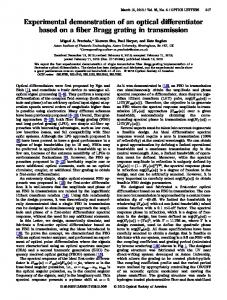
FIG. 1. (Color online). (a) Scanning electron microscopy of the coupled resonator system which consists of one single-leg cantilever D which works as a transducer and a double-leg cantilever T whose motion is under transducing, with gold on the surface being colored. (b) A schematic diagram illustrating the thermal noise spectra (green arrow: drive, blue arrow: output of FC) and the frequency of pumping field (red arrow). (c) A simplified schematic diagram consisting of the circuit of signal generating for the pumping and drive signals (left), the electric and mechanical operation of the device (middle), and the data processing (right). A magnetic field B is applied along z axis in order to produce the Lorentz force to drive the resonant T when a voltage of frequency ωt is between the two legs of resonator T. A pumping voltage consisting of the superposition of d.c and a.c. signals is used to generate the coupling between the two resonators via electrostatic force. The effective capacity is of the order of 1 fF, and the frequency of the a.c. pumping field ωpu is set to satisfy the relation ωpu = ωd − ωt . The reference frequency of demodulation is set at ωd .
voltage Vpu (t) between the two resonators, there is an electrostatic force produced, which results in a effective pumping field η(t) = (1/2)(∂ 2 C/∂ 2 x)Vpu (t)2 in unit of N/m [31]. Here C(xt − xd ) is the effective capacity between the two resonators. In practice, Vpu (t) is d.c. realized by a superposition of a d.c. voltage Vpu and a.c. an a.c. voltage Vpu cos(ωpu t) of frequency ωpu satisfying Eq. (2). In this case, only the cross term of Vpu (t)2 actually contributes to the FC process due to frequency constrains and the effective coupling strength is then η = d.c. a.c. 1/2(∂ 2 C/∂ 2 x)Vpu Vpu (see Supplementary information for details). The experiments were carried out at room temperature on the device suspended with springs in a vacuum chamber of pressure lower than 10−8 mbar. The basic parameters of resonators were measured by fiber interferometer which consists of a 1550 nm-distributed-feedback laser diode using 90/10 optical coupler, the laser was focused on the end of the resonator by a lens so that resonators
3 T and D could be measured individually. The resonators T and D have natural resonance frequencies ωt = 6.76 kHz and ωd =37.41 kHz in absence of externally applied d.c. voltage, and quality factors Qt = 1200 and Qd = 1700 obtained by free ring down. th The thermal noise spectral densities Sx,{t,d} (ω) were measured optically. Then by applying the equipartition R ∞ th theorem [30] kB T /kt,d = 2 0 Sx,{t,d} (ω)dω/2π, the effective spring constants were calculated to be kt = 0.071 N/m and kd = 1.0 N/m. The equation of motion for a damped harmonic oscillator leads to th th 4 2 2 2 Sx,{t,d} (ω) = SF,{t,d} ωt,d /kt,d [(ωt,d −ω 2 )2 +ωt,d ω 2 /Q2t,d ], from which the frequency-independent thermal force th noise density SF,{t,d} can be calculated. From the th th measured Sx,{t,d} (ω), we obtained SF,t = 3.4 × 10⁻¹⁵ √ √ th −15 N/ Hz, and peak N/ Hz and SF,d = 4.6 × 10 √ −11 displacement noises 5.6 m/ Hz for resonator T √ × 10 and 0.74 × 10⁻¹¹ m/ Hz for resonator D.
(a )
(c ) 0 V
2
1 V 2 V
1
3 V
(n m )
(n m )
∆xd of resonator D was measured optically and plotted in Fig. 2(a) as a function of ωdr . It is important to ascertain that the ωdr dependence of ∆xd actually gives the frequency-domain behavior of resonator T. This is confirmed by the fact that the ∆xd curve in Fig. 2(a) coincides in both peak frequency and width with the thermal noise spectrum of resonator T plotted in Fig. 2(b), which was obtained from direct optical measurement. Measured results of ∆xd for a series of applied a.c. pumping voltages are plotted in Fig. 2(c). The measured peak amplitude increases with the a.c. increase of Vpu proportionally, indicating that stronger pumping field can be used to produce stronger signal at resonator D for detection. However, deviation from this proportionality becomes apparent for strong enough pumping, as shown later in Fig. 3(a). Under a fixed d.c. a.c. amplitude of Vpu and Vpu while varying the amplitude of Vdr , the displacement ∆xd of resonator D is shown in Fig. 2(d) to be proportional to the displacement ∆xt of the target resonator T, as expected. These results show that the motion of resonator T is transduced to resonator D via the parametrical coupling process.
4 V
d
(a )
(b )
(d )
6 .7 6
6 .7 7
6 .7 8
1 0
-1
8
)
1
(m /N )
(n m ) 4
1 0 1
(d )
1 0
3 0
6 .7 6
6 .7 7
F re q u e n c y (k H z )
6 .7 8
0
5
1 0
1 5
x t
2 0
2 5
3 0
3 5
(n m )
(n m )
2 0
t
1 .0
1 0
1 0
G
6 .7 5
x
6 .7 4
0
6 .7 3
1 0
a n d 1 /h
S
2
5
0 .8
4
1 /c
x
d
-2
(c )
1 0
6
-1 3
1 0
-1
1 0
1 /2
(n m /H z
6 .7 5
F re q u e n c y (k H z )
x
1 /2
6 .7 4
F
6 .7 3
6 .7 8
6 .7 7
d
6 .7 6
-1 2
1 0
x
6 .7 5
F re q u e n c y (k H z )
(b ) 1 0
6 .7 4
0
1 0
6 .7 3
(n m )
0
d
0 .1
(N )
x
d
x
5 V
0
FIG. 2. (Color online). (a) Dependence of ∆xd on the frequency ωdr of the drive field exerted on resonator T. In the measurement, the frequency ωpu was tuned to ωpu = ωd − ωdr when ωdr was swept. (b) The optically measured thermal noise spectrum of resonator T. (c) Same as (a) but for a a.c. variety of a.c. pumping voltages Vpu . It is noted that for a.c. the case Vpu = 0, i.e., the a.c. pumping voltage being tuned off, ∆xd is flat at zero, as expected. (d) The displacements ∆xd for resonator D versus ∆xt for resonator T under a fixed pumping voltage, with red line being a linear fitting. The black curves in the sub-figures (a-c) are fits of Lorentz shape to guide eyes.
We first studied the frequency-domain behavior of resonator T under external excitation by monitoring the motion of resonator D. In order to do this, the reference frequency in demodulation (Fig. 1(c)) was fixed at ωd , and the frequencies of both the drive and the a.c. pump voltages were swept under the constraint ωpu = ωd − ωdr , d.c. a.c. and the amplitude of Vdr , Vpu and Vpu were set at 100 µV, 20 V and 3 V, respectively. The amplitude
1
1 0
V
a .c . p u
1
1 0
( v o lts )
FIG. 3. (Color online). (a) Variation of the measured amplitude of resonator D (circles) and the corresponding theoretical curve with a.c. pumping voltage. (b) Variation of the measured force (circles) and the corresponding theoretical value (grey curve) with a.c. pumping voltage. (c) The measured coupling strength η (empty circles) and effective transduction factor χ (solid circles) for different a.c. pumping voltages and their theoretical curves. (d) The calculated motion amplitude of resonator T from transduction process (solid blue circles) and the one directly measured by optical method (empty black circles) for different a.c. pumping voltages and the theoretical value (grey curves), subset is the measured gain factor G (solid circles) and the theoretical curve.
We further studied the dependence of the transduction process on the coupling strength when resonator T was under coherent resonant excitation and the FC was satisfied, i.e, ωdr = ωt and ωpu = ωd − ωt . The
4
Having demonstrated the transduction of motion from resonators T to D, we investigated the noise of the d.c. transduction process. The amplitudes of Vdr and Vpu were set the same as those used to obtain Fig. 3. We first studied the transduction noise measured by resonator D. Fig. 4(a) shows the transduction imprecision tot derived from the optically measured data of SF,d , i.e., the force noise density of resonator D under pumping, q p th /η and the total Sxim = SF,d using the definition q p tot /χ. It shows that transduction noise Sxtot = SF,d √ a.c. when Vpu = 9.5 V, the imprecision is 3.9×10⁻¹¹ m/ Hz, which is smaller than the intrinsic displacements noise of resonator T. The back-action of the transduction process was studied by measuring optically the q force noises of th ) and on resonator T when the pumping was off ( SF,t q tot th tot ). ( SF,t The ratio SF,t /SF,t is plotted in Fig. 4(b) together with theoreticalqcurves. The back-action force tot − S th for the measured SF,t noise calculated using F,t √ a.c. data when Vpu = 9.5 V is only 0.8 × 10⁻¹⁵ N/ Hz, √ with a statistic error of 1.4 × 10⁻¹⁵ N/ Hz. In conclusion, we have explored a method to realize motion transduction by the FC process using parametric
(a ) -9
(m /H z
1 /2
)
1 0
-1 0
S
x
1 /2
1 0
1
(b )
1 0
1 .0
F
to t
/S
F
th
1 .2
S
d.c. amplitudes of Vdr and Vpu were set at 100 µV and 36 V, a.c. respectively. The amplitude Vpu was varied from 0.5 to 10 V. The results are plotted in Fig. 3. The displacement response of resonator D in Fig. 3(a) shows that under weak pumping the response increases linearly with a.c. pumping voltage, but as the pumping field increases further, nonlinear behavior appears, which fits well to the theoretical model and gives ∂ 2 C/∂ 2 x = 6.5×10⁻⁷ F/m2 . Fig. 3(b) plots the corresponding force felt by resonator D which was calculated by using ∆Fd = ∆xd kd /(G · on off Qd ), where the gain factor G = ∆xpump /∆xpump t,d t,d was obtained from the optically measured displacements on off ∆xpump and ∆xpump . It shows the proportionality t t of ∆Fd to the a.c. pumping voltage, as expected. Fig. 3(c) plots the coupling strength η derived from measured data by using ∆Fd /(G · ∆xt ) and the effective transduction factor χ by using ∆Fd /∆xt . It shows that 1/χ equals 1/η under weak pumping, but is smaller than 1/η for strong pumping, as a result of the nonlinearity of the transduction process (see Supplementary information for details). The motion of resonator T measured by the transduction is compared to the one measured directly by optical method in Fig. 3(d). The agreement is reasonable well and becomes better when the pumping for parametric coupling becomes gradually stronger. The decrease of ∆xt with the increase of pumping voltage clearly shows the decrease in the target resonator’s susceptibility to external driving force, by the extent described by the gain factor G plotted as subset of Fig. 3(d).
0 .8 1
V
a .c . p u
( v o lts )
1 0
FIG. 4. (Color online). (a) Measured noise of the transduction process at a measurement bandwidth of 1 Hz: imprecision noise (solid circles), total noise (empty circles), and their corresponding theoretical curves. Error bars show the corresponding statistical fluctuation. Dashed horizontal line is the thermal noise of resonator T. (b) The ratio of the tot under pumping against the measured force noise density SF,d th intrinsic force noise density SF,d without pumping. The grey regime shows the calculated contributions of the back-action.
coupling between two separate mechanical resonators, and then designed experiments to test the scheme. Both the transduction imprecision and the back-action force are substantially smaller than the intrinsic noise level of the resonator being transferred, and this demonstrates the efficiency of the motion transduction. Now we discuss the application of the scheme to weak force sensing. Supposing that the motion to be detected is from an ultra-sensitive cantilever (resonator T) with frequency 10 kHz, force sensitivity the order of 10−21 √ N/ √Hz and thermal displacement noise the order of 10−9 m / Hz, and the resonator with frequency about 1 MHz and being monitored by a superconducting cavity at about 100 mK [21] can be taken as resonator D, we can realize the motion transduction with back-action force much smaller than the force noise level of resonator T, while at the same time the motion transduction efficiency is maintained (see Supplementary information for more details). Combining the transduction scheme with feedback control on resonator D can further improve the transduction sensitivity and realize dynamical cooling of resonator T, which is out of the scope of this work. We thank Fei Xue for help in setting up the
5 experimental hardwares and Yiqun Wang from Suzhou Institute of Nano-Tech and Nano-Bionics for fabricating the mechanical resonators. This work was supported by the National Key Basic Research Program of China (Grant No. 2013CB921800), the National Natural Science Foundation of China (Grant Nos. 11227901, 91021005, 11274299, 11104262 and 10834005) and the ‘Strategic Priority Research Program (B)’ of the CAS (Grant No. XDB01030400).
∗ [email protected] [1] A. N. Cleland and M. L. Roukes, Nature (London) 392, 160 (1998). [2] D. Rugar, R. Budakian, H. J. Mamin, and B. W. Chui, Nature (London) 430, 329 (2004). [3] K. Jensen, K. Kim, and A. Zettl, Nature Nanotech. 3, 533(2008). [4] A. C. Bleszynski-Jayich, W. E. Shanks, B. Peaudecerf, E. Ginossar, F. von Oppen, L. Glazman, and J. G. E. Harris, Science 326, 272 (2009). [5] A. Eichler, J. Moser, J. Chaste, M. Zdrojek, I. Wilson-Rae, and A. Bachtold, Nature Nanotech. 6, 339 (2011). [6] J. M. Nichol , E. R. Hemesath , L. J. Lauhon, and R. Budakian, Phys. Rev. B 85, 054414 (2012). [7] J. S. Bunch , A. M. van der Zande, S. S. Verbridge, I. W. Frank , D. M. Tanenbaum, J. M. Parpia, H. G. Craighead, and P. L. McEuen, Science 315 (5811), 490–493(2007). [8] A. A. Clerk, M. H. Devoret, S. M. Girvin, F. Marquardt, and R. J. Schoelkopf, Rev. Mod. Phys.82, 1155 (2010). [9] O. Arcizet, P.-F. Cohadon, T. Briant , M. Pinard , A. Heidmann, J. M. Mackowski, C. Michel, L. Pinard, O. Francais, and L. Rousseau, Phys. Rev. Lett. 97, 133601 (2006). [10] P. Verlot, A. Tavernarakis , T. Briant , P.-F. Cohadon, and A. Heidmann, Phys. Rev. Lett. 104, 133602 (2010). [11] A. Naik, O. Buu, M. D. LaHaye, A. D. Armour, A. A. Clerk, M. P. Blencowe, and K. C. Schwab, Nature (London) 443, 193 (2006). [12] A. Schliesser, O. Arcizet, R. Rivi`ere, G. Anetsberger, and T. J. Kippenberg, Nature Phys.5, 509 (2009).
[13] R. G. Knobel, and A. N. Cleland, Nature (London) 424, 291 (2003). [14] M. D. LaHaye , O. Buu, B. Camarota, and K. C. Schwab, Science 304, 74 (2004). [15] A. N. Cleland , J. S. Aldridge , D. C. Driscoll, and A. C. Gossard, Appl. Phys. Lett. 81, 1699 (2002). [16] M. Poggio, M. P. Jura , C. L. Degen , M. A. Topinka, H. J. Mamin , D. Goldhaber-Gordon, and D. Rugar, Nature Phys.4, 635 (2008). [17] S. Etaki, M. Poot, I. Mahboob , K. Onomitsu, H. Yamaguchi, and H. S. J. van der Zant, Nature Phys.4, 785 (2008). [18] C. A. Regal, J. D. Teufel, and K. W. Lehnert, Nature Phys. 4, 555 (2008). [19] S. Kolkowitz, A. C. B. Jayich, Q. P. Unterreithmeier, S. D. Bennett, P. Rabl, J. G. E. Harris, and M. D. Lukin, Science 335, 1603 (2012). [20] N. E. Flowers-Jacobs, D. R. Schmidt, and K. W. Lehnert, Phys. Rev. Lett. 98, 096804 (2007). [21] J. D. Teufel, T. Donner, M. A. Castellanos-Beltran , J. W. Harlow, and K. W. Lehnert, Nature Nanotech. 4, 820 (2009). [22] L. F. Wei, Y.-X. Liu, C. P. Sun, and F. Nori, Phys. Rev. Lett. 97, 237201 (2006). [23] R. B. Karabalin, M. C. Cross, and M. L. Roukes, Phys. Rev. B 79, 165309 (2009). [24] R. B. Karabalin, Ron Lifshitz, M. C. Cross , M. H. Matheny , S. C. Masmanidis, and M. L. Roukes, Phys. Rev. Lett. 106, 094102 (2011). [25] K. L. Turner, S. A. Miller, P. G. Hartwell, N. C. MacDonald, S. H. Strogatz, and S. G. Adams, Nature (London) 396, 149 (1998). [26] Q. P. Unterreithmeier , E. M. Weig, and J. P. Kotthaus, Nature (London) 458, 1001 (2009). [27] I. Bargatin , I. Kozinsky, and M. L. Roukes. Appl. Phys. Lett. 90, 093116 (2007). [28] I. Mahboob, K. Nishiguchi, H. Okamoto and H. Yamaguchi, Nature Phys.8, 387 (2012). [29] Should symmetrized noise spectrum densities were employed, nd +1 should be replaced by nd +1/2, which is essentially the same, especially at high temperature (see Supplementary information for details). [30] J. A. Sidles, J. L. Garbini, and G. P. Drobny, Rev. Sci. Instrum.63, 3881 (1992). [31] D. Rugar, and P. Gr¨ utter, Phys. Rev. Lett. 67, 699 (1991).