coatings Article
Deposition of Photocatalytic TiO2 Coating by Modifying the Solidification Pathway in Plasma Spraying Kui Wen 1,2 1 2
3
*
ID
, Min Liu 1,2 , Xuezhang Liu 1,2,3, *
ID
, Chunming Deng 2 and Kesong Zhou 1,2, *
ID
School of Materials Science and Engineering, Central South University, Changsha 410083, China;
[email protected] (K.W.);
[email protected] (M.L.) National Engineering Laboratory for Modern Materials Surface Engineering Technology, The Key Lab of Guangdong for Modern Surface Engineering Technology, Guangdong Institute of New Materials, Guangzhou 510651, China;
[email protected] School of Materials and Mechanical Engineering, Jiangxi Science and Technology Normal University, Nanchang 330013, China Correspondence:
[email protected] (X.L.);
[email protected] (K.Z.)
Received: 21 September 2017; Accepted: 11 October 2017; Published: 13 October 2017
Abstract: The deposition of photocatalytic TiO2 coatings with plasma spraying is attractive for large-scale applications due to its low cost and simplicity, but it is still a challenge to obtain a TiO2 coating with high anatase content. The solidification pathway of inflight melted particles was investigated in the present paper, and TiO2 coatings with enhanced photocatalytic activity were obtained without a significant loss of the microhardness. The coating microstructure, phase composition, and crystallite size were investigated by scanning electron microscopy (SEM) and X-ray diffraction (XRD). Photocatalytic performance was evaluated by decomposing an aqueous solution of methylene blue. Results showed that the anatase content in TiO2 coating was augmented to 19.9% from 4%, and the time constant of the activity was increased to 0.0046 h−1 from 0.0017 h−1 . Keywords: photocatalytic coatings; solidification; plasma spraying; TiO2 ; microstructure
1. Introduction Titanium dioxide (TiO2 ) has been extensively investigated due to its high photocatalytic activity [1,2]. There are three normal crystal phases for TiO2 material: brookite, anatase, and rutile. Under atmosphere pressure and temperature, rutile is the stable phase. Calcined at the temperature about 573 to 1073 K, anatase and brookite will irreversibly transform into rutile. However, the photocatalytic activity of rutile is lower than that of anatase due to an increased electron-hole recombination rate [3,4]. The deposition of TiO2 coating well attached on the surface of a substrate can be more efficient and as compared to TiO2 P25 powder or similar products, owing to the easy recovery of the photocatalyst from the water [5]. Several methods have been reported to prepare TiO2 coatings, including vapor deposition [6,7], electrophoretic deposition [8,9], sol-gel [10], and thermal spraying [11]. In comparison to other methods, thermal spraying has several highlighted features to make it particularly attractive, which include flexibility and high efficiency. Unfortunately, during the thermal spraying of a plasma jet with a temperature of 14,000 K, the powder feedstock is melted. These molten particles are then driven to deposit on a substrate. Compared with initial feedstock powders, the anatase transformation to rutile is clearly observed in sprayed coatings. Even given P25/20 TiO2 granulated nanopowders as the starting powder, an anatase content of only 1.7%–5% were obtained in the coatings [12]. Then, retaining the metastable anatase phase in thermally sprayed TiO2 coatings becomes a great challenge. Coatings 2017, 7, 169; doi:10.3390/coatings7100169
www.mdpi.com/journal/coatings
Coatings 2017, 7, 169
2 of 9
Bozorgtabar et al. [12] demonstrated that photocatalytic activity was strongly related to the process conditions of thermal spraying. Thus, Colmenares-Angulo et al. [13] adjusted spraying conditions to reduce the heat input, and expected to reduce the transformation of anatase TiO2 to rutile. Ctibor et al. [14] reported that most of the reduced phases were formed in TiO2 coatings. The stoichiometry was further found to be a function of process parameters. Zhang et al. [15] reported that oxygen vacancies at the surface remarkably prolonged the life of the photon-generated carrier. Thus, it significantly increased the activity. However, others have recently observed that oxygen vacancies caused a significant raise to the charge carrier recombination and resulted into a depressed photocatalytic activity [16]. Herein, modifying the solidification pathway of inflight melted particles was investigated by injecting distilled water into the plasma jet rather than adjusting the spray conditions, and photocatalytic TiO2 coatings with enhanced activity were obtained. The elaborated coating microstructure was mainly characterized by SEM, while phase composition and crystallite size were investigated by XRD. Finally, the photocatalytic activity of the proposed TiO2 coatings was evaluated by decomposing an aqueous solution of methylene blue. 2. Experimental 2.1. Atmospheric Plasma Spraying An atmospheric plasma spraying system (MF-P1000, GTV, Luckenbach, Germany) was used to deposit TiO2 coatings. A carrier gas with a flow rate of 3.5 L/min radially injected feedstock powder into the plasma jet, while distilled water was radially injected into the plasma jet through a nozzle with average diameter of 0.3 mm by a suspension feeder (GTV, Luckenbach, Germany). The powder injector was 8.0 mm apart from the gun outlet, while the solution injector was 15.0 mm away from the gun outlet. Three typical coatings were obtained with different feeding parameters. As seen in Table 1, the speed of the feed disc regulated the mass of the feedstock powder injected into the plasma jet, and the flow rate controlled the mass of distilled water injected into the jet. Table 1. The details of plasma spraying parameters for TiO2 coatings. Spraying Parameters Spraying current (A) Spraying voltage (V) Primary gas Ar (L/min) Secondary gas H2 (L/min) Speed of feed disc (rpm) Spraying distance (mm) Flow rate (mL/min)
Samples TiO2 -12-0
TiO2 -12-30
TiO2 -20-30
650 69 40 10 1.2 100 0
650 69 40 10 1.2 100 30
650 69 40 10 2.0 100 30
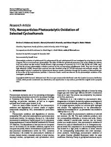
Micron-sized commercial TiO2 powders (−45 + 15 µm, Sunspraying Science and Technology Co. Ltd., Beijing, China) were adopted as feedstock powders (Figure 1). Stainless steel plates (30 mm in diameter, STS316) were employed as substrates. Prior to the deposition, the substrates were cleaned with ethanol to remove contaminants, followed by blasting with Al2 O3 abrasives. 2.2. Coating Characterization Scanning electron microscopy (SEM, Nova-Nona-430, Thermo Fisher Scientific, Waltham, MA, USA) was utilized to investigate the microstructure of TiO2 coatings. A UV-Vis spectrophotometer (HP8453, Agilent, Santa Clara, CA, USA) was used to record spectra in the wavelength range of 250 to 750 nm. Microhardness was obtained with a load of 100 g for 10 s using Vickers (2100B, Instron Tukon, Shanghai, China), and the value was averaged from five indents per specimen.
Coatings 2017, 7, 169 Coatings 2017, 7, 169
3 of 9 3 of 9
An X-ray diffractometer (XRD, D8-Advance, Bruker, Billerica, MA, USA) equipped with copper An X‐ray diffractometer (XRD, D8‐Advance, Bruker, Billerica, MA, USA) equipped with copper radiation X-ray was employed to assess the phase composition of the proposed coatings. The 2θ was radiation X‐ray was employed to assess the phase composition of the proposed coatings. The 2θ was acquired in the range of 20◦ to 90◦ with a 0.05◦ step size. The anatase content was simply determined by acquired in the range of 20° to 90° with a 0.05° step size. The anatase content was simply determined the the use of the given given by Berger-Keller et al. [17]. crystallitecrystallite size was calculated by use of relationship the relationship by Berger‐Keller et Meanwhile, al. [17]. Meanwhile, size was using the Scherrer formula [18]. calculated using the Scherrer formula [18].
Figure 1. (a) SEM morphology and (b) XRD pattern of feedstock powders. Figure 1. (a) SEM morphology and (b) XRD pattern of feedstock powders.
2.3. Photocatalytic Activity 2.3. Photocatalytic Activity The photocatalytic behavior the TiO TiO2 coatings coatings was was assessed assessed from from decomposing decomposing methylene methylene The photocatalytic behavior of of the 2 blue (MB) in a home‐made setup. The coated samples were immersed in a glass reactor containing blue (MB) in a home-made setup. The coated samples were immersed in a glass reactor containing 2 50 mL of MB solution (5 ppm), and then illuminated with a UV‐lamp (λ = 370 nm, I = 2.5 mW/cm 50 mL of MB solution (5 ppm), and then illuminated with a UV-lamp (λ = 370 nm, I = 2.5 mW/cm2). ). The concentration of MB was determined at certain intervals by measuring the solution absorbance The concentration of MB was determined at certain intervals by measuring the solution absorbance with a UV‐visible spectrometer at 664 nm wavelength, which was the maximum absorption peak of with a UV-visible spectrometer at 664 nm wavelength, which was the maximum absorption peak MB. of MB. 3. Results and Discussion 3. Results and Discussion 3.1. Crystal Structure and Phase Composition 3.1. Crystal Structure and Phase Composition The crystal structure and phase composition of as-deposited coatings were mainly analyzed by The crystal structure and phase composition of as‐deposited coatings were mainly analyzed by XRD. Figure 2 illustrates the patterns, where the dominant phase is rutile. The minor phase is anatase. XRD. Figure 2 illustrates the patterns, where the dominant phase is rutile. The minor phase is anatase. It is interesting that there is some preferred orientation in XRD patterns. This may be resulted from the It is interesting that there is some preferred orientation in XRD patterns. This may be resulted from lamellar structure of as-deposited TiO2 coatings stacked by flat granules, it should beit investigated the lamellar structure of as‐deposited TiO2 coatings stacked by flat but granules, but should be further. Additionally, Ti8 O15 phases are in all of as-prepared samples, which is consistent investigated further. Additionally, Ti 8O15observed phases are observed in all of as‐prepared samples, which is with other works [13,19]. For TiO2 coatings sprayed by thermal plasma, Magneli phases were widely consistent with other works [13,19]. For TiO 2 coatings sprayed by thermal plasma, Magneli phases reported [20]. This is mainly ascribed to the reduction of TiO2 , which results from the high temperature were widely reported [20]. This is mainly ascribed to the reduction of TiO 2, which results from the high temperature of the thermal plasma jet. There may be other reduced phases, but the analysis is of the thermal plasma jet. There may be other reduced phases, but the analysis is inconclusive because inconclusive because the crystallite size is very small. the crystallite size is very small. As shown in Figure 2, the peak intensity of 2θ = 25.25° (101) becomes stronger as distilled water As shown in Figure 2, the peak intensity of 2θ = 25.25◦ (101) becomes stronger as distilled water is injected into the plasma jet. The XRD results illustrate that the total amount of anatase phase is is injected into the plasma jet. The XRD results illustrate that the total amount of anatase phase is increased by modifying the solidification pathway. Moreover, the anatase content and crystallite size increased by modifying the solidification pathway. Moreover, the anatase content and crystallite size are calculated by the Berger‐Keller relationship and Scherrer formula, respectively. The results are are calculated by the Berger-Keller relationship and Scherrer formula, respectively. The results are demonstrated in Table 2. demonstrated in Table 2. At atmospheric pressure, anatase and brookite are two metastable phases. They can transform At atmospheric pressure, anatase and brookite are two metastable phases. They can transform to to rutile at temperature the temperature of 573–1073 K. However, from a thermodynamics view, the rutile at the rangerange of 573–1073 K. However, from a thermodynamics view, the nucleation nucleation from the be melt could be by the temperature and rate quenching rate [12]. Though from the melt could modified bymodified the temperature and quenching [12]. Though anatase is a anatase is a metastable phase, it preferentially solidifies with a high quenching rate due to its lower surface energy in comparison to rutile (γAnatase = 0.38 J∙m−2, γRutli = 0.93 J∙m−2) [11,21].
Coatings 2017, 7, 169
4 of 9
metastable phase, it preferentially solidifies with a high quenching rate due to its lower surface energy in comparison to rutile (γAnatase = 0.38 J·m−2 , γRutli = 0.93 J·m−2 ) [11,21]. Coatings 2017, 7, 169 4 of 9
Figure 2. XRD patterns of TiO Figure 2. XRD patterns of TiO22 coatings: (a) TiO coatings: (a) TiO22‐12‐0, (b) TiO -12-0, (b) TiO22‐12‐30, and (c) TiO -12-30, and (c) TiO22‐20‐30. -20-30. Table 2. Phase compositions and crystallites size of TiO Table 2. Phase compositions and crystallites size of TiO22 coatings. coatings. Items
TiO2‐12‐0 Items TiO2 -12-04.0 Anatase (Vol %) Anatase crystallites average size (nm) Anatase (Vol %) 4.0 30.4 Rutile crystallites average size (nm) Anatase crystallites average size (nm) 30.4 73.0 Rate constant (h Rutile crystallites average size (nm)−1) 73.0 0.0017 − 1 0.00170.9965 Rate constant (h )R2 0.9965 R2
Samples Samples TiO 2‐12‐30 TiO2‐20‐30 TiO 11.0 19.8 TiO2 -20-30 2 -12-30 22.2 19.9 11.0 19.8 40.2 27.0 22.2 19.9 0.0045 0.0046 27.0 40.2 0.0045 0.9966 0.9894 0.0046 0.9966 0.9894
During the plasma spraying process, the plasma temperature is higher than 14,000 K. The speed can reach about 500 m/s [22]. TiO 2 particles are fully heated by the plasma jet. Consequently, these During the plasma spraying process, the plasma temperature is higher than 14,000 K. The speed molten particles with high temperature deposit on the substrate. As the solidification temperature is can reach about 500 m/s [22]. TiO2 particles are fully heated by the plasma jet. Consequently, these close to the melting point of TiO 2, the particles are apt to nucleate into stable rutile. Therefore, the molten particles with high temperature deposit on the substrate. As the solidification temperature rutile phase (96%) in the coating is obtained, and the crystallite size is 73 nm. is close to the melting point of TiO2 , the particles are apt to nucleate into stable rutile. Therefore, the when distilled water is injected the plasma jet, stream is fragmented into rutileHowever, phase (96%) in the coating is obtained, andinto the crystallite size is the 73 nm. smaller drops and then evaporated. The evaporation of the droplet solvent can carry off a great deal However, when distilled water is injected into the plasma jet, the stream is fragmented into of heat drops from and melted and quenching with moderate smaller then particles, evaporated. Thethose evaporation of theparticles droplet solvent can carry temperature off a great dealare of deposited on the substrate. Thus, the particles solidify with the temperature lower than the melting heat from melted particles, and those quenching particles with moderate temperature are deposited point of TiO 2 and generate the anatase phase. As a result, the anatase content is 11% and 19.9% for on the substrate. Thus, the particles solidify with the temperature lower than the melting point of TiO2 TiO 2 ‐12‐30 and TiO 2‐20‐30, and the crystallite size is 22.21 and 19.9 nm. and generate the anatase phase. As a result, the anatase content is 11% and 19.9% for TiO2 -12-30 and TiO2 -20-30, and the crystallite size is 22.21 and 19.9 nm. 3.2. Morphology Characterization 3.2. Morphology Characterization The photocatalytic performance of TiO2 coatings is directly correlated to phase compositions and The photocatalytic performance TiOmorphology directly correlated toof phase microstructural characteristics. Thus, ofthe microstructure TiO2 compositions coatings are 2 coatings is and and microstructural characteristics. Thus, the morphology and microstructure TiO2 coatings investigated by SEM. The surface micrographs of TiO2 coatings are shown in of Figure 3. It can are be investigated by SEM. The surface micrographs of TiO coatings are shown in Figure 3. It can be observed that there is no significant discrepancy among these coated samples. They are all composed 2 observed that there is no significant discrepancy among these coated samples. They are allDuring composed of fully molten areas and insufficient molten areas; the latter exhibit a rough surface. the of fully molten areas insufficient molten areas;heats the latter exhibit particles a rough surface. During the the spraying process, the and plasma jet of high enthalpy the injected and accelerates spraying process, the plasma jet of high enthalpy heats the injected particles and accelerates the melting melting to form solidified droplets (or splats) onto the substrate. Meanwhile, small voids are observed to form solidified droplets (or splats) onto the substrate. Meanwhile, small voids are observed in in coating surface. This is mainly ascribed to un‐melted particles. As a result, the pores and roughness can increase the reaction area between the catalyzer and the solution during the degradation of the MB dye.
Coatings 2017, 7, 169
5 of 9
coating surface. This is mainly ascribed to un-melted particles. As a result, the pores and roughness can increase the reaction area between the catalyzer and the solution during the degradation of the Coatings 2017, 7, 169 5 of 9 MB dye.
Figure 3. SEM images of TiO2 coatings: (a1–a3) TiO Figure 3. SEM images of TiO 2‐12‐0, (b1–b3) TiO 2‐12‐30, and (c1–c3) TiO ‐20‐30. 2 coatings: (a1–a3) TiO 2 -12-0, (b1–b3) TiO 2 -12-30, and (c1–c3) 2TiO 2 -20-30.
The corresponding cross‐sections are illustrated in Figure 3 as well. Along with the morphology, The corresponding cross-sections are illustrated in Figure 3 as well. Along with the morphology, those coatings all exhibit lamella structure. Meanwhile, the TiO those coatings all exhibit lamella structure. Meanwhile, the TiO22 coatings are firmly bonded to the coatings are firmly bonded to the stainless steel substrates, and there is no crack at the interface. For the TiO ‐12‐0 coating, some voids stainless steel substrates, and there is no crack at the interface. For the TiO22-12-0 coating, some voids are observed, observed, which which may may be be resulted resulted from from the the relaxation relaxation of of the the thermal thermal stress stress of of inter-laminar inter‐laminar or or are incomplete contact between the plates and un‐melted particles. When modifying the solidification incomplete contact between the plates and un-melted particles. When modifying the solidification pathway, the the cross‐section of TiO the 2TiO 2‐12‐30 coating becomes the decreases porosity obviously. decreases pathway, cross-section of the -12-30 coating becomes fine andfine the and porosity obviously. On the other hand, the coating of TiO 2‐20‐30 presents a rough and porous cross‐section On the other hand, the coating of TiO2 -20-30 presents a rough and porous cross-section that is caused that is caused by the lower melting point of the particles. by the lower melting point of the particles. In addition, addition, the the thicknesses thicknesses of of TiO TiO22-12-0, ‐12‐0, TiO TiO22-12-30, ‐12‐30, and and TiO TiO22‐20‐30 about 150, 150, 180, 180, and and In -20-30 are are about 200 μm, respectively. The increased thicknesses of TiO 2 ‐20‐30 can be ascribed to the augmented speed 200 µm, respectively. The increased thicknesses of TiO2 -20-30 can be ascribed to the augmented speed of the feed disc (from 1.2 to 2.0 rpm). As the speed increases, more TiO 2 particles are injected into the of the feed disc (from 1.2 to 2.0 rpm). As the speed increases, more TiO 2 particles are injected into plasma jet and take part in coating deposition. However, it is interesting that the the thickness of the plasma jet and take part the in the coating deposition. However, it is interesting that thickness TiO 2 ‐12‐30 also becomes thicker when compared with TiO 2 ‐12‐0, because the speed of feed disc is of TiO2 -12-30 also becomes thicker when compared with TiO2 -12-0, because the speed of feed disc is 1.2 rpm. The results imply that distilled water injected into the plasma jet can not only modify the 1.2 rpm. The results imply that distilled water injected into the plasma jet can not only modify the solidification pathway pathway inflight melted 2 particles, but also can increase the deposition solidification ofof inflight melted TiO2TiO particles, but also can increase the deposition efficiency. efficiency. Further study will be carried out to clarify this in future. Further study will be carried out to clarify this in future.
Coatings 2017, 7, 169
6 of 9
3.3. Microhardness Functional coatings need sufficient mechanical properties and desired microstructures, while among the mechanical properties, the microhardness plays an important role on the long-term stability. Therefore, the influence of modifying the solidification pathway on the microhardness of TiO2 coatings was reviewed. The value of HV 100 is 1148.27 for the TiO2 -12-0 coating. When adopting the modification, HV 100 of the TiO2 -12-30 coating changes to 1137.8. This implies that there is no different discrepancy to the microhardness. With the modification, distilled water with a flow rate of 30 mL/min is radially injected into the plasma jet. The evaporation of water decreases the temperature of the plasma jet. However, the solution injector is 15.0 mm away from the gun outlet, which is located downstream of the powder injector, and thus the optimized injection does not violently affect the molten status of TiO2 particles except those in the solidification pathway. Therefore, it does not cause a significant change to the microhardness. However, the HV 100 value slightly decreases to 1064.04 in the TiO2 -20-30 coating. The reason for this can be ascribed to the molten status of TiO2 particles. As the speed of the feed disc increases from 1.2 to 2.0 rpm, more TiO2 particles are injected into the plasma jet core. The temperature of the plasma jet already becomes lower with the modification of the solidification pathway, compared with TiO2 -12-0. Then, the heat energy shared by a single TiO2 particle further decreases as more TiO2 particles exist in the plasma jet, and some particles impact the substrate as un-melted or partially melted particles. As clarified in Figure 3(c2), this results in a rough and porous cross-section. Consequently, it slightly reduces the microhardness. 3.4. Photocatalytic Properties The UV-Vis diffuse reflectance spectra of TiO2 coatings were firstly recorded in the wavelength range of 250–750 nm. The results are illustrated in Figure 4. All coatings have an absorbance edge in the range of 390–400 nm, which is characteristic of semiconductor coatings. The absorbance edge is ascribed to the charge transfer from the valence band to the conduction band. For TiO2 materials, the valence band is largely caused by 2p orbitals of the oxide anions, and the conduction band is constituted with 3d t2g orbitals of the Ti4+ cations [23]. These charge carriers present high reactive activity and can act with different paths. One is the recombination of electron-hole pairs without taking part in the degradation. The other involves gathering at the surface, and reacting with the pollutant [24]. In comparison, all of the spectra show similar curve shapes without new spectrum phenomena. Although the solidification pathway is modified, no notable shift to longer or shorter wavelengths was observed in the TiO2 -12-30 and TiO2 -20-30 coatings. Perhaps the main reason for this is that the rutile phase still dominates in both coatings, though the anatase content increases. The photocatalytic performances are shown in Figure 5. All coatings present different degrees of activity in decomposing methylene blue with the irritation of UV light. The coating of TiO2 -12-0 shows depressed photocatalytic activity. This is consistent with other works [12,13]. Without modifying the solidification pathway, the anatase content in this coating is as low as 4%. For the TiO2 -12-30 and TiO2 -20-30 coatings, they both exhibit a significant increase in photocatalytic activity. Obviously, the enhanced activity is ascribed to the augmented anatase content in both TiO2 coatings because they present similar structure. As the TiO2 -20-30 coating has a higher anatase content than TiO2 -12-30, it presents higher activity. Furthermore, the variation in MB concentration with irradiation time is coincident with Langmuir-Hinshelwood model. The kinetics equation can be depicted by −ln C/C0 = kt, where C and C0 are the measured concentration of MB and the initial concentration, respectively, and k is the time constant of the activity (h−1 ). By a first-order fitting of the exponential term to the time t, the values of k are obtained for all coatings and summarized in Table 2. As presented in Table 2, the k value for the TiO2 -12-30 or TiO2 -20-30 coating is higher than that of the TiO2 -12-0 coating, as the former is
Coatings 2017, 7, 169
7 of 9
deposited with the modification of the solidification pathway. As clarified by the equation, the bigger value k implies higher photocatalytic activity. Coatingsof 2017, 7, x FORaPEER REVIEW 7 of 9
Coatings 2017, 7, 169
7 of 9
The photocatalytic performances are shown in Figure 5. All coatings present different degrees of activity in decomposing methylene blue with the irritation of UV light. The coating of TiO2‐12‐0 shows depressed photocatalytic activity. This is consistent with other works [12,13]. Without modifying the solidification pathway, the anatase content in this coating is as low as 4%. For the TiO2‐ 12‐30 and TiO2‐20‐30 coatings, they both exhibit a significant increase in photocatalytic activity. Obviously, the enhanced activity is ascribed to the augmented anatase content in both TiO2 coatings because they present similar structure. As the TiO2‐20‐30 coating has a higher anatase content than Figure UV-Visreflectance reflectancespectra spectraofofTiO TiO2 coatings: coatings: (a) and (c) TiO2-20-30. Figure 4. 4.UV-Vis (a) TiO TiO22-12-0, -12-0,(b) (b)TiO TiO2-12-30, 2 2 -12-30, and (c) TiO2 -20-30. TiO2‐12‐30, it presents higher activity. The photocatalytic performances are shown in Figure 5. All coatings present different degrees of activity in decomposing methylene blue with the irritation of UV light. The coating of TiO2-12-0 shows depressed photocatalytic activity. This is consistent with other works [12,13]. Without modifying the solidification pathway, the anatase content in this coating is as low as 4%. For the TiO212-30 and TiO2-20-30 coatings, they both exhibit a significant increase in photocatalytic activity. Obviously, the enhanced activity is ascribed to the augmented anatase content in both TiO 2 coatings because they present similar structure. As the TiO2-20-30 coating has a higher anatase content than TiO2-12-30, it presents higher activity.
Figure 5. Photocatalytic activity in decomposing methylene blue of TiO 2 coatings: (a) TiO2‐12‐0, (b) Figure 5. Photocatalytic activity in decomposing methylene blue of TiO 2 coatings: (a) TiO2 -12-0, TiO 2‐12‐30, and (c) TiO2‐20‐30. (b) TiO -12-30, and (c) TiO -20-30. 2
2
Furthermore, the variation in MB concentration with irradiation time is coincident with 4. Conclusions Langmuir‐Hinshelwood model. The kinetics equation can be depicted by −ln C/C0 = kt, where C and Distilled water was injected into the plasma jet to modify the solidification pathway of inflight C0 are the measured concentration of MB and the initial concentration, respectively, and k is the time −1). By a first‐order fitting of the exponential term to the time t, the values of melted TiO2 particles rather than adjusting the spray conditions. Results showed that the anatase constant of the activity (h phase was nucleated from melted TiO2 particles under a high cooling rate due to its lower surface k are obtained for all coatings and summarized in Table 2. As presented in Table 2, the k value for the energy comparing to the rutile phase, and photocatalytic TiO2‐12‐0 coating, as the former is deposited 2 coatings with enhanced activity were TiO 2‐12‐30 or TiO 2‐20‐30 coating is higher than that of the TiO Figure 5. Photocatalytic activity in decomposing methylene blue of TiOto 2 coatings: (a) TiO2-12-0, (b) obtained. Finally, the anatase content in TiO2 coatings was augmented 19.9% from 4%, and the time with the modification of the solidification pathway. As clarified by the equation, the bigger value of TiO 2-12-30, and (c) TiO2-20-30. − 1 − 1 constant of the activity was increased to 0.0046 h from 0.0017 h . In addition, the modification of k implies a higher photocatalytic activity. the solidification pathway did not remarkably cause the loss of coating microhardness. Furthermore, the variation in MB concentration with irradiation time is coincident with 4. Conclusions Langmuir-Hinshelwood model. The kinetics equation can be depicted by −ln C/C0 = kt, where C and C0 areDistilled water was injected into the plasma jet to modify the solidification pathway of inflight the measured concentration of MB and the initial concentration, respectively, and k is the time melted 2 particles than adjusting fitting the spray Results showed that the anatase constantTiO of the activityrather (h−1). By a first-order of theconditions. exponential term to the time t, the values of phase was nucleated from melted TiO 2 particles under a high cooling rate due to its lower surface k are obtained for all coatings and summarized in Table 2. As presented in Table 2, the k value for the energy comparing to the rutile phase, and photocatalytic TiO 2 coatings with enhanced activity were TiO2-12-30 or TiO2-20-30 coating is higher than that of the TiO2-12-0 coating, as the former is deposited obtained. Finally, the anatase content in TiO 2 coatings was augmented to 19.9% from 4%, and the with the modification of the solidification pathway. As clarified by the equation, the bigger value of −1 from 0.0017 h−1. In addition, the modification time constant of the activity was increased to 0.0046 h k implies a higher photocatalytic activity.
Coatings 2017, 7, 169
8 of 9
Acknowledgments: This work has been financially supported by Guangdong Natural Science Foundation (2016A030312015), Guangdong Academy of Sciences (2017GDASCX-0202, 2017GDASCX-0843, 2016GDASPT-0206, 2016GDASPT-0317). Author Contributions: Kui Wen, Xuezhang Liu and Kesong Zhou conceived and designed the experiments; Kui Wen and Xuezhang Liu performed the experiments; Kui Wen, Xuezhang Liu, Min Liu and Chunming Deng analyzed the data; Xuezhang Liu and Kui Wen wrote and revised the paper respectively. Conflicts of Interest: The authors declare no conflict of interest.
References 1.
2.
3.
4. 5. 6.
7. 8.
9.
10.
11. 12. 13.
14.
15.
16.
Priyanka, K.P.; Revathy, V.R.; Rosmin, P.; Thrivedu, B.; Elsa, K.M.; Nimmymol, J.; Balakrishna, K.M.; Varghese, T. Influence of La doping on structural and optical properties of TiO2 nanocrystals. Mater. Charact. 2016, 113, 144–151. [CrossRef] Daram, P.; Banjongprasert, C.; Thongsuwan, W.; Jiansirisomboon, S. Microstructure and photocatalytic activities of thermal sprayed titanium dioxide/carbon nanotubes composite coatings. Surf. Coat. Technol. 2016, 306, 290–294. [CrossRef] Zelekew, O.A.; Kuo, D.-H.; Yassin, J.M.; Ahmed, K.E.; Abdullah, H. Synthesis of efficient silica supported TiO2 /Ag2 O heterostructured catalyst with enhanced photocatalytic performance. Appl. Surf. Sci. 2017, 410, 454–463. [CrossRef] Chung, L.; Chen, W.F.; Koshy, P.; Sorrell, C.C. Effect of Ce-doping on the photocatalytic performance of TiO2 thin films. Mater. Chem. Phys. 2017, 197, 236–239. [CrossRef] Cravanzola, S.; Jain, S.M.; Cesano, F.; Damin, A.; Scarano, D. Development of multifunctional TiO2 /MWCNT hybrid composite grafted on stainless-steel grating. RSC Adv. 2015, 5, 103255–103264. [CrossRef] Quesada-Gonzalez, M.; Boscher, N.D.; Carmalt, C.J.; Parkin, I.P. Interstitial boron-doped TiO2 thin films: The significant effect of boron on TiO2 coatings grown by atmospheric pressure chemical vapor deposition. ACS Appl. Mater. Interfaces 2016, 8, 25024–25029. [CrossRef] [PubMed] Taherniya, A.; Raoufi, D. The annealing temperature dependence of anatase TiO2 thin films prepared by the electron-beam evaporation method. Semicond. Sci. Technol. 2016, 31, 125012. [CrossRef] Chava, R.K.; Lee, W.M.; Oh, S.Y.; Jeong, K.U.; Yu, Y.T. Improvement in light harvesting and device performance of dye sensitized solar cells using electrophoretic deposited hollow TiO2 NPs scattering layer. Sol. Energy Mater. Sol. Cells 2017, 161, 255–262. [CrossRef] Liu, C.F.; Huang, C.P.; Hu, C.C.; Juang, Y.J. Photoelectrochemical degradation of dye wastewater on TiO2 -coated titanium electrode prepared by electrophoretic deposition. Sep. Purif. Technol. 2016, 165, 145–153. [CrossRef] Anitha, V.S.; Lekshmy, S.S.; Joy, K. Effect of annealing on the structural, optical, electrical and photocatalytic activity of ZrO2 -TiO2 nanocomposite thin films prepared by sol-gel dip coating technique. J. Mater. Sci. Mater. Electron. 2017, 28, 10541–10554. [CrossRef] Mauer, G.; Guignard, A.; Vaßen, R. Plasma spraying of efficient photoactive TiO2 coatings. Surf. Coat. Technol. 2013, 220, 40–43. [CrossRef] Bozorgtabar, M.; Rahimipour, M.; Salehi, M.; Jafarpour, M. Structure and photocatalytic activity of TiO2 coatings deposited by atmospheric plasma spraying. Surf. Coat. Technol. 2011, 205, S229–S231. [CrossRef] Colmenares-Angulo, J.; Zhao, S.; Young, C.; Orlov, A. The effects of thermal spray technique and post-deposition treatment on the photocatalytic activity of TiO2 coatings. Surf. Coat. Technol. 2009, 204, 423–427. [CrossRef] Ctibor, P.; Seshadri, R.C.; Henych, J.; Nehasil, V.; Pala, Z.; Kotlan, J. Photocatalytic and electrochemical properties of single- and multi-layer sub-stoichiometric titanium oxide coatings prepared by atmospheric plasma spraying. J. Adv. Ceram. 2016, 5, 126–136. [CrossRef] Zhang, J.; Zhao, Z.; Wang, X.; Yu, T.; Guan, J.; Yu, Z.; Li, Z.; Zou, Z. Increasing the oxygen vacancy density on the TiO2 surface by La-doping for dye-sensitized solar cells. J. Phys. Chem. C 2010, 114, 18396–18400. [CrossRef] Rajender, G.; Giri, P.K. Strain induced phase formation, microstructural evolution and bandgap narrowing in strained TiO2 nanocrystals grown by ball milling. J. Alloy. Compd. 2016, 676, 591–600. [CrossRef]
Coatings 2017, 7, 169
17. 18. 19.
20.
21. 22. 23.
24.
9 of 9
Berger-Keller, N.; Bertrand, G.; Filiatre, C.; Meunier, C.; Coddet, C. Microstructure of plasma-sprayed titania coatings deposited from spray-dried powder. Surf. Coat. Technol. 2003, 168, 281–290. [CrossRef] Chen, D.; Jordan, E.H.; Gell, M. Porous TiO2 coating using the solution precursor plasma spray process. Surf. Coat. Technol. 2008, 202, 6113–6119. [CrossRef] Shen, P.K.; He, C.; Chang, S.; Huang, X.; Tian, Z. Magnéli phase Ti8O15 nanowires as conductive carbon-free energy materials to enhance the electrochemical activity of palladium nanoparticles for direct ethanol oxidation. J. Mater. Chem. A 2015, 3, 14416–14423. [CrossRef] Dosta, S.; Robotti, M.; Garcia-Segura, S.; Brillas, E.; Cano, I.G.; Guilemany, J.M. Influence of atmospheric plasma spraying on the solar photoelectro-catalytic properties of TiO2 coatings. Appl. Catal. B Environ. 2016, 189, 151–159. [CrossRef] Hanaor, D.A.H.; Sorrell, C.C. Review of the anatase to rutile phase transformation. J. Mater. Sci. 2011, 46, 855–874. [CrossRef] Cizek, J.; Khor, K.A.; Dlouhy, I. In-flight temperature and velocity of powder particles of plasma-sprayed TiO2 . J. Therm. Spray Technol. 2013, 22, 1320–1327. [CrossRef] Carneiro, J.O.; Azevedo, S.; Fernandes, F.; Freitas, E.; Pereira, M.; Tavares, C.J.; Lanceros-Méndez, S.; Teixeira, V. Synthesis of iron-doped TiO2 nanoparticles by ball-milling process: The influence of process parameters on the structural, optical, magnetic, and photocatalytic properties. J. Mater. Sci. 2014, 49, 7476–7488. [CrossRef] Toma, F.-L.; Berger, L.-M.; Shakhverdova, I.; Leupolt, B.; Potthoff, A.; Oelschlägel, K.; Meissner, T.; Gomez, J.A.I.; De Miguel, Y. Parameters influencing the photocatalytic activity of suspension-sprayed TiO2 coatings. J. Therm. Spray Technol. 2014, 23, 1037–1053. [CrossRef] © 2017 by the authors. Licensee MDPI, Basel, Switzerland. This article is an open access article distributed under the terms and conditions of the Creative Commons Attribution (CC BY) license (http://creativecommons.org/licenses/by/4.0/).