Design and Development of a Low-cost Flexure-based Hand-held. Mechanism for Micromanipulation. U-Xuan Tan, Win Tun Latt, Cheng Yap Shee, and Wei ...
2009 IEEE International Conference on Robotics and Automation Kobe International Conference Center Kobe, Japan, May 12-17, 2009
Design and Development of a Low-cost Flexure-based Hand-held Mechanism for Micromanipulation U-Xuan Tan, Win Tun Latt, Cheng Yap Shee, and Wei Tech Ang Abstract— This paper presents a 3-DOF low-cost hand-held micromanipulator driven by 3 piezoelectric actuators and built using rapid prototyping. Traditional pin and ball joints have been commonly replaced by flexure-based methods in the field of micromanipulation. Utilization of flexure-based joints have several advantages like the non-existence of backlash and assembly errors. However, most of the present flexurebased mechanisms are bulky and not suitable for hand-held applications. It is difficult and expensive to make such compact mechanism using traditional machining methods. In additional, traditional machining methods are limited to simple design. To reduce the cost of fabrication and also to allow more complex designs, Objet (a rapid prototyping machine) is proposed to be used to build the mechanism. With regards to hand-held applications, the size of the mechanism is a constraint. Hence, a parallel manipulator design is the preferred choice as compared to a serial mechanism because of its rigidity, compactness, and simplicity in design. For the illustration of an application, the mechanism is designed with an intraocular needle attached to it. Possible applications of this design include enhancement of performance in microsurgery and cell micromanipulation. Experiments are also conducted to evaluate the manipulator’s tracking performance of the needle tip at a frequency of 10Hz. Index Terms— Flexure joints, parallel mechanism, micromanipulator, medical robotics, and rapid prototyping.
I. INTRODUCTION There is a need for manipulators with high accuracy and rapid response in many applications. Conventional mechanisms with traditional motors, gears and revolute joints are not able to meet the requirements. Their coarse accuracy is caused by the existence of backlash and friction between moving parts. Hence, flexure joints are more popularly used. Flexure joints have been used in precision instruments like watches and clocks since many years ago. Ever since the seminal work of Paros and Weisbord [1], there has been an increase in usage of flexure-based mechanism in new applications, such as optical systems and micro-robots, where precision is of great importance. Flexure joints offer several significant advantages [2], [3] and are typically manufactured monolithically. Hence, errors due to assembly can be avoided. No sliding parts are also required in flexure-based mechanism. Thus, lubricant is not needed, making it suitable for applications like medical This work was supported in part by College of Engineering, Nanyang Technological University, and in part by Agency for Science, Technology and Research (A*STAR) SERC grant. U-X. Tan, W. T. Latt, C. Y. Shee and W. T. Ang are with School of Mechanical and Aerospace Engineering, Nanyang Technological University, Singapore {tanu0002, wintunlatt, cyshee, wtang} @
ntu.edu.sg
978-1-4244-2789-5/09/$25.00 ©2009 IEEE
surgery which require clean and sterile environment. More importantly, flexure joints generate smooth displacement without backlash. As long as the flexure joints are not pushed into their plastic region, the joints are able to produce predictable and repeatable motions. These advantages make flexure-based mechanism attractive in applications involving micro-scale precision motion [4], [5]. One of the desired tools that scientists and doctors want is a hand-held manipulator. With such manipulators, manipulation by the users can be enhanced by guided motion using sensors or vision methods. Choi and Riviere [6] designed a similar tool for tremor cancellation. In order to meet the hand-held requirement, size is a concern. Thus, parallel mechanism is preferred over serial mechanisms because of its compactness. Parallel manipulators also have advantages like no accumulative error and high rigidity. Tang and Chen [7] proposed an XYZ-flexure parallel mechanism with large displacement and decoupled kinematics structure. Dong et al. [5] proposed a wide-ranged flexure hinge-based parallel manipulator while Yi et al. [8] focused on XY θZ stages. However, it is expensive and difficult to make a compact parallel micromanipulator using traditional machining methods. Processes like electro-discharge machining (EDM) are able to produce precise cutting, but the cost is expensive. In addition, machining methods are limited to simple designs. Complicated 3-D designs are not allowed as there must be space available for the cutting tool to reach. To save cost, rapid-prototyping machine is proposed. In this paper, Objet is used and the material used is VeroWhite. The part is built layer by layer. The supports used is a gellike material. The gel-like support material can be easily removed by hand and water. In addition, solvent can be used to dissolve the support material. Complicated mechanisms can be easily built and available for use within a day. This paper presents a 3-DOF low-cost hand-held manipulator for micromanipulation. Section II provides the design while section III describes how the manipulator is fabricated. Section IV explains the kinematics and section V shows the experimental results. Section VI and VII covers the discussion and conclusion respectively. II. DESIGN The proposed hand-held instrument is a 3-DOF manipulator that is driven by 3 piezoelectric actuators. Piezoelectric actuators are used because of its good resolution, rapid response and high bandwidth. Fig. 1 shows a photo of the manipulator. There are two portions. The upper portion is
4350
the mechanism while the lower part houses the piezoelectric actuators. The two parts are connected via screws. Fig. 2 shows the mechanism while Fig. 3 is the schematic diagram of the mechanism.
The mechanism used is a parallel mechanism. There are three limbs connecting the moving platform to the base platform. Each limb consists of a prismatic joint in series with a pin joint and a universal joint. The main function of the prismatic joint is to provide a spring like effect to keep the actuators in contact with the base. The mechanism is designed in such a way that the actuator is pre-stressed when the mechanism is attached to the holder. The size of the manipulator is small enough for handheld purpose. The diameter of the mechanism (excluding the holder) is 27mm and the height from the mechanism’s base to the moving platform is 17mm. The diameter of the holder is 22mm and the height of the holder actually depends on the length of the actuator, which is dependent on the stroke length required for the application. In this paper, the height of the holder is 57mm. A male luer connector is also built on the moving platform. A needle is attached to the moving platform via tight fit with the male luer connector. For a wider range of usage, the design of the connector can be changed to other type of connectors accordingly to suit the required tool to be used. III. FABRICATION
Fig. 1.
Photo of the mechanism with actuator holder
Fig. 2.
Fig. 3.
Exploded view of the mechanism
Schematic Diagram of the Mechanism
The cost of building the lower and upper part is SGD $100 Singapore Dollars each, making the total cost to be SGD$200, which is less than USD$150. Designing the upper portion (mechanism) for traditional machining will easily involve more than 20 parts and will cost more than SGD$2000. In addition, errors due to assembly, backlash and friction will come into play. Thus, it is proposed that the mechanism to be built as a single piece using rapid prototyping. No assembly will be required for the mechanism portion. In addition, the cost of rapid prototyping is less than 10% of the traditional machining cost. To save cost, the lower portion is fabricated using traditional machining. As for the complicated upper portion, Objet is used to build the part. The material used is VeroWhite. VeroWhite is jetted onto the build tray in thin layers. The part is built layer by layer till the whole part is completed. Each layer is cured by UV light immediately after it is jetted onto the build tray. This results in a fully cured model and can be used immediately. No post-curing is required. The supports that are used in the building is a gel-like material. The gel-like support material can be easily removed by hand and water. In addition, certain solvent can be used to dissolve those support material that cannot be reached by hand. Thus, complicated mechanism can be easily built and available for use within a day. There is one major issue to note when using rapid prototyping machine for flexure-based mechanism. The part is built layer by layer as shown in Fig. 4 and the side is not very smooth. As flexure joints involve bending, there is higher stress concentration on the sides. In addition, the bonding strength between layers is weaker than the material’s tensile strength. To avoid the mechanism failure due to the layers’ issues, instead of building from the bottom of the mechanism to the
4351
Fig. 4.
Part built layer by layer
top, the mechanism is built from left to right. The mechanism is configured to be built in the manner shown in Fig 5. In this way, the stress due to most of the bending will be up taken up by the material, and not by the bond between layers.
Therefore, the wrench (reciprocal screws that are reciprocal to all) are: 1 W1 = [0 1 0 0 0 0]T 1 W2 = [0 0 0 0 0 1]T Doing likewise for the other 2 limbs, the wenches are: √ 2 W1 = [− 3/2 − 1/2 0 0 0 0 0]T 2 T W2 = [0 √0 0 0 0 1] 3 W1 = [ 3/2 − 1/2 0 0 0 0 0]T 3 W2 = [0 0 0 0 0 1]T The net wrench is thus: ⎞ ⎛ 0 1 0 0 0 0 ⎜ 0 0 0 0 1 ⎟ ⎟ ⎜ √0 ⎜ − 3/2 −1/2 0 0 0 0 ⎟ ⎟ (2) W = ⎜ ⎜ 0 0 0 0 1 ⎟ ⎟ ⎜ √0 ⎝ 3/2 −1/2 0 0 0 0 ⎠ 0 0 0 0 0 1 Hence, the degree of freedom is (6-3) = 3. In addition, it can be seen that the degree of freedom in this particular state are z, θx and θy . B. Inverse Kinematics
Fig. 5.
Orientation of the Mechanism in the Rapid Prototyping Machine
IV. KINEMATICS This section first analyzes the degree of freedom of the mechanism. This is followed by the inverse kinematics that is used to calculate the required actuation input. A. Degree of Freedom In this paper, screw theory is used to determine the degree of freedoms. Reciprocal screws are used over Grashof criterion because there are a few similar constrains in the joints of a parallel mechanism. Basics of reciprocal screws to analyze the mechanism can be found in [9] and [10]. In summary, given a parallel mechanism with m limbs and n joints per limb, the net motion twist system is 1 $ ∩ 2 $ ∩ . . . m $ while the net wrench system is 1 W � ∪ 2 W � ∪ . . . m W � . Degree of freedom of a parallel mechanism is given by: = rank[(1 $1 +1 $2 + . . . +1 $n ) ∩ (2 $1 +2 $2 + . . . + 2 $n ) ∩ . . . ∩ (m $1 +m $2 + . . . +m $n )] =
6 − rank[(1 W1 +1 W2 + . . . +1 Wn ) ∩ (2 W1 + 2 W2 + . . . +2 Wn ) ∩ . . . ∩ (m W1 +m W2 + . . . +m Wn )]
(1)
In this parallel mechanism, there are 3 limbs. For this section, the fix frame is placed at frame {1}’s location. In the first limb, the screws are: $1 = [0 0 0 0 0 1]T $2 = [0 1 0 L 0 r]T with r2 = [r 0 − L]T $3 = [1 0 0 0 0 0]T with r3 = [r 0 0]T $4 = [0 1 0 0 0 r]T with r4 = [r 0 0]T
This section describes the inverse kinematics that is used to calculate the actuation input. The style on how the inverse kinematics is obtained is similar to what Lee et al. [11]– [13] proposed, with some modification as the mechanism and point of interest is slightly different. A schematic diagram of the mechanism is shown in Fig. 3. The moving platform, {1}, is connected to the base, {0}, by means of an extensible link, in series with a pin joint followed by an universal joint. The actuators are equally spaced at 120◦ and a radius of r from the center of the base. Hence, the coordinates of the pin joints with respect to {0} are: ⎡ ⎡ 1 ⎤ ⎤ ⎤ ⎡ − −√12 r r r √2 0 P1 = ⎣ 0 ⎦ ,0 P2 = ⎣ 23 r ⎦ ,0 P3 = ⎣ − 23 r ⎦ (3) l1 l2 l3 Similarly, the universal joints are equally spaced at a radius r from the center of the moving platform and the coordinates of the universal joints with respect to {1} are: ⎡ ⎤ ⎡ 1 ⎤ ⎡ ⎤ −√12 r r − r √2 1 U1 = ⎣ 0 ⎦ ,1 U2 = ⎣ 23 r ⎦ ,1 U3 = ⎣ − 23 r ⎦ (4) 0 0 0 The position and orientation of {1} with respect to {0} can related by a homogeneous transformation. The transformation matrix to map {1} to {0} is given by: ⎡ ⎤ nx ox ax xc ⎢ ny oy ay yc ⎥ ⎥ (5) T01 = ⎢ ⎣ nz oz az zc ⎦ 0 0 0 1 T
T
T
where [nx ny nz ] , [ox oy oz ] and [ax ay az ] are the directional cosines vectors. At initialization, the origin of {1} with respect to {0} is given by [0 0 zc0 ]T . The length of the link between the ith pin joint and ith universal joint is � � � � � � L = �0 U1 −0 P1 � , L = �0 U2 −0 P2 � , L = �0 U3 −0 P3 � (6)
4352
where L is the length of the link connecting the pin joint and universal joint. Thus, 2
L2
And also, nx − oy
2
= (nx r + xc − r) + (ny r + yc ) +
= Cα2 Cβ + Sα2 − Sα2 Cβ − Cα2 = C2α Cβ − C2α
2
(nz r + zc − l1 ) (7) � �2 √ 1 −nx r + 3ox r + 2xc + r + L2 = 4 � √ √ �2 1 −ny r + 3oy r + 2yc − 3r + 4 �2 √ 1� −nz r + 3oz r + 2zc − 2l2 (8) 4 � � 2 √ 1 −nx r − 3ox r + 2xc + r + L2 = 4 � √ √ �2 1 −ny r − 3oy r + 2yc + 3r + 4 �2 √ 1� −nz r − 3oz r + 2zc − 2l3 (9) 4 The design of the flexure joints, which ideally imposes the physical constraints equivalent to pin joints, limit the universal joints to move in the respective planes: √ √ y = 0 , y = − 3x and y = 3x (10) This means that the position of the universal joints, Ui , are constrained into these three planes respectively. The constraint equations are thus: (11) ny r + yc = 0 � √ � √ −ny r+ 3oy r+2yc = − 3 −nx r + 3ox r + 2xc (12) � √ √ � √ −ny r − 3oy r + 2yc = 3 −nx r − 3ox r + 2xc (13)
(14) ny = ox 1 xc = r(nx − oy ) (15) 2 By expressing the directional cosines in terms of the famous Z-Y-Z Euler angles (α, β, γ), T01 can be expressed as: ⎡ ⎤ Cα Cγ Cβ − Sα Sγ −Cα Sγ Cβ − Sα Cγ Cα Sβ xc ⎢ Sα Cγ Cβ + Cα Sγ −Sα Sγ Cβ + Cα Cγ Sα Sβ yc ⎥ ⎢ ⎥ ⎣ −Cγ Sβ Sγ Sβ Cβ zc ⎦ 0 0 0 1 Thus, α
= tan−1
β
= tan−1
ay ax �
(16) n2z + o2z az
oz −nz In addition, equation (14) becomes: γ
= tan−1
Sα Cγ (Cβ + 1) ⇒
= tanα
−Cα Sγ (1 + Cβ ) = −tanγ
⇒ ⇒
α+γ α
= nπ = −γ ∵ n = 0
(17) (18)
(20)
Hence, respectively from (14) and (11), xc yc
1 = − r(1 − Cβ )C2α 2 1 r(1 − Cβ )S2α = 2
(21) (22)
Hence, xc , yc , γ and the directional cosines vectors can be expressed in terms of α, β and zc . However, the end effector of the micromanipulator is the tip of the needle. Hence, the inputs to the inverse kinematics should be [dx dy dz ]T , which is the desired displacement of the needle’s tip from the initial position. Since ⎡ ⎡ ⎤ ⎤ ⎡ ⎤ 0 0 dx ⎢ 0 ⎥ ⎢ ⎢ dy ⎥ ⎥ 0 ⎢ ⎢ ⎥ ⎥ ⎢ ⎥ (23) ⎣ dz ⎦ = T01 ⎣ ltip ⎦ − ⎣ zc0 + ltip ⎦ 1 1 1 dx , dy and dz can be written as:
√
By adding (12) with (13) and also substracting (12) from (13), the constraint equations respectively becomes:
= Cα Cγ Cβ − Sα Sγ + Sα Sγ Cβ − Cα Cγ
dx
= xc + ltip ax
(24)
dy dz
= yc + ltip ay = zc − zc0 + ltip (az − 1)
(25) (26)
By replacing xc , ax , yc and ay with α and β, dx and dy can be expressed as: dx dy
1 = − r(1 − Cβ )C2α + Cα Sβ ltip 2 1 r(1 − Cβ )S2α + Sα Sβ ltip = 2 ≈ Sα Sβ ltip ∵ β is small
(27)
(28)
As the range of motion of the manipulator is not big, β is small and (1 − Cβ ) can be approximated to be zero. Hence, � � dy α = tan−1 (29) dx � � dx (30) β = sin−1 Cα ltip where − π2 ≤ α ≤ π2 , − π2 ≤ β ≤ π2 . xc , yc , γ can be expressed in terms of α, β and zc using (21), (22), and (19) respectively and T01 is in terms of α, β and γ. In addition, α, β and zc can be calculated using (29), (30) and (26) respectively. Hence, l1 , l2 and l3 can be found by solving equations (7), (8) and (9) respectively. C. Workspace
(19)
Using a piezoelectric actuator P885.90 from Physik Instrumente stacked with a P885.50 as the input actuation, the workspace of the manipulator is shown in Fig. 6, in which the stroke length for each input is limited to 45m.
4353
absolute root mean square error can be found along with the root mean square error in the x, y and z axis component.
z (µm)
50
0 200
VI. DISCUSSION y (µm)0
−200
Fig. 6.
100 0 −200 −100 x (µm)
200
The performance of the micromanipulator can be seen from table I. It can be seen that the absolute root mean square errors for all the trajectories are less than 7μm. These trajectories were driven at 10Hz with a amplitdue of 85μm. In other words, the amplitude in the acceleration domain is 335.6mm/s2 .
Workspace of the manipulator
V. EXPERIMENTAL RESULTS In this section, a brief description of the experiment setup is first given, followed by the results. The piezoelectric actuator used for each input is a P885.90 from Physik Instrumente stacked with a P885.50. The total stroke length for each input is about 45μm. The controller used to remove the hysteretic effect of the piezoelectric actuators is the one that Ang et al. [14] proposed.
Meausred Desired
z (mm) 0.1 0.05 0
A. Experiment Setup In this paper, all the displacement readings of the end effector is measured by system, developed by Win et al. [15] using position sensitive devices, with a RMS error of 0.7 μm. The experiment setup is as shown in Fig. 7.
−0.05 −0.1 0.1 y (mm)
Fig. 8.
0 −0.1
−0.1
0.05 0 −0.05 x (mm)
0.1
3-D plot of the end effector when driven to draw a circle
Displacement along y−axis (µm)
0.1
Fig. 7.
Measured Desired 0.05
0
−0.05
Experiment Setup −0.1
For measurement purpose, the needle is replace by a rod with a ball attached to the end. The ball is placed such that it is the same as the position of the needle’s tip. The ball is required to be used to reflect the IR waves to the position sensitive devices.
0
0.1
Fig. 9.
0.2
0.3 0.4 Time (s)
0.5
0.6
0.7
1-D plot of Fig. 8 in the y-axis component
0.08 0.06
B. Results
0.04
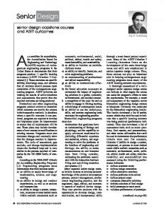
A number of experiments were conducted to demonstrate the performance of the manipulator. The first experiment is to move the end effector in a circular path with a radius of 85μm at a frequency of 10Hz. Fig. 8 shows the 3-D plot of the result while Fig. 9 shows the result in the y-axis component. Next, the end effector is driven to move in a couple of straight lines of a length of 170μm at a frequency of 10Hz along y=x, y-axis and x-axis. The result of the trajectory is shown in Fig. 10, 11 and 12 respectively. Table I summaries the numerical results for all. In this table, the
4354
0.02 Y (mm) 0 −0.02 −0.04 −0.06 −0.08 −0.08−0.06−0.04−0.02 0 0.02 0.04 0.06 0.08 X (mm)
Fig. 10.
2-D plot of the end effector when driven to move along y=x
joint and the mechanism will not behave like before.
0.08
VII. CONCLUSION
0.06
This paper presents a 3-DOF low-cost hand-held micromanipulator that is built using a rapid prototyping machine and driven by piezoelectric actuators. The total cost of building this prototype is SGD$200 Singapore dollars (less than USD$150). Experiments were also conducted to evaluate the mechanism’s performance. The mechanism was driven at a relatively high frequency of 10 Hz for a couple of different paths. The amplitude of the acceleration is 335.6mm/s2 and the root mean square errors for all the different trajectories were found to be less than 7μm.
0.04 0.02 Y (mm) 0 −0.02 −0.04 −0.06 −0.08 −0.08−0.06−0.04−0.02 0 0.02 0.04 0.06 0.08 X (mm)
Fig. 11.
2-D plot of the end effector when driven to move along y-axis
ACKNOWLEDGMENTS The authors would like to thank Prof. Chua Chee Kai and his Ph.D student, Tan Jia Yong, of Nanyang Technological University for the usage of their rapid prototyping machine.
0.08 0.06 0.04
R EFERENCES
0.02 Y (mm) 0 −0.02 −0.04 −0.06 −0.08 −0.08−0.06−0.04−0.02 0 0.02 0.04 0.06 0.08 X (mm)
Fig. 12.
2-D plot of the end effector when driven to move along x-axis TABLE I E XPERIMENTAL R ESULTS Type of Motion
x rmse
y rmse
z rmse
rmse
circle
4.5061
4.9720
1.6137
6.9014
straight line along x-axis
4.3429
2.8307
1.6383
5.4367
straight line along y-axis
1.8563
4.0526
1.0122
4.5710
straight line along y=x 4.2612 4.3842 0.9994 6.1950 This table summarizes the experimental results. All the readings are in μm. All the motions are driven at 10Hz with an amplitude of 85μm (170μm peak-peak). The data are collect over 2.5 sec. x rmse, y rmse and z rmse are the root mean square errors along x, y and z axis. The rmse root mean square of the absolute errors.
One major disadvantage of using rapid prototyping is its poorer resolution as compared to more precise machining. Modeling of the mechanism is important for close loop control. However, as the dimension is not that accurate, the model of the mechanism that is obtained through theoretical calculations does not fit the actual mechanism well. In addition, the mechanism is built layer by layer. The properties of the material is not isotropic and same throughout. This makes modeling of the mechanism even more challenging. Another precaution is that the actuations must not be large till the flexure joints reaches the material’s plastic region. The consequence is the permanent deformation of the flexure
[1] J. M. Paros, and L. Weisbord, “How to Design Flexure Hinges,” Mach. Des., vol. 37, no. 27, pp.151-156, 1965. [2] L. L. Howell, Compliant Mechanisms, New York: Wiley, 2001. [3] S. Kota, “Compliant systems using monolithic mechanisms,” Smart Material Bulletin, pp. 7-9, Mar., 2001. [4] B. H. Kang, J. T.-Y. Wen, N. G. Dagalakis, and J. J. Gorman, “Analysis and Design of Parallel Mechanisms with Flexure Joints,” IEEE Transactions on Robotics, vol. 21, no. 6, pp. 1179-1185, Dec., 2005. [5] W. Dong, Z. J. Du, and L. N. Sun, “Conceptional Design and Kinematics Modeling of a Wide-Range Flexure Hinge-Based Parallel Manipulator,” IEEE International Conference on Robotics and Automation, Barcelona, Spain, April, 2005. [6] D. Y. Choi, and C. N. Riviere, “Flexure-based Manipulator for Active Handheld Microsurgical Instrument,” 27th Annual International Conference of the IEEE Engineering in Medicine and Biology Society (EMBS), pp. 2325 - 2328, Shanghai, China, Sept., 2005. [7] X. Y. Tang, and I-M. Chen, “A Large-Displacement 3-DOF Flexure Parallel Mechanism with Decoupled Kinematics Structure,” IEEE/RSJ International Conference on Intelligent Robots and Systems, pp. 16681673, Beijing, China, Oct., 2006. [8] B.-J. Yi, G. B. Chung, H. Y. Na, W. K. Kim, and I. H. Suh, “Design and Experiment of a 3-DOF Parallel Micromechanism Utilizing Flexure Hinges,” IEEE Transactions on Robotics and Automation, vol. 19, no. 4, pp. 604-612, Aug., 2003. [9] L. W. Tsai, “The Jacobian Analysis of a Parallel Manipulator Using Reciprocal Screws,” Institute for System Research Technical Research Report, T.R.98-34, 1998. [10] L. W. Tsai, Robot Analysis- The Mechanics of Serial and Parallel Manipulators, John Wiley & Sons, Inc, New York, USA, 1999. [11] K. M. Lee, and D. K. Shah, “Kinematic Analysis of a Three-Degrees of Freedom In-Parallel Actuated Mechanism,” IEEE Journal of Robotics & Automation, vol. 4, no. 3, pp. 354-360, 1988. [12] K. M. Lee, and D. K. Shah, “Dynamic Analysis of a Three-Degrees-ofFreedom In-Parallel Actuated Manipulator,” IEEE Journal of Robotics and Automation, vol. 4, no. 3, pp. 361-367, June, 1988. [13] K. M. Lee, and S. Arjunan, “A Three-Degrees-of-Freedom Micromotion In-Parallel Actuated Manipulator,” IEEE Transaction on Robotics & Automation, vol. 7, no. 5, pp. 634-641, Oct., 1991. [14] W. T. Ang, C. N. Riviere, and P. K. Khosla, “Feedforward Controller With Inverse Rate-Dependent Model for Piezoelectric Actuators in Trajectory-Tracking Applications,” IEEE/ASME Transactions on Mechatronics, vol. 12, no. 2, pp. 1-8, April, 2007. [15] T. L. Win, U. X. Tan, C. Y. Shee, and W. T. Ang, “Design and Calibration of an Optical Micro Motion Sensing System for Micromanipulation tasks,” IEEE International Conference on Robotics and Automation, pp. 3383-3388, Roma, Italy, April, 2007.
4355