Design and Evaluation of a Multi-Robot Control Interface B. Trouvain and H.L. Wolf Forschungsgesellschaft für Angewandte Naturwissenschaften Neuenahrer Str. 53 53343 Wachtberg GERMANY E-mail:
[email protected],
[email protected]
ABSTRACT Designing a human-machine interface for a semi-autonomous mobile multi-robot system is a challenging task. The requirements range from operating in a real time environment, facilitating asynchronous command execution to supporting the operator in dividing his monitoring and control resources among multiple robots. This paper presents the results of two simulations based multi-robot experiments being conducted to guide and support the development of our multi-robot control interface. Robot autonomy represents a requirement for a multi-robot system managed by a single operator. Understanding the impact of varying levels of robot autonomy on operator performance is important for the interface design process. In separate trials operators had to manage 2, 4 and 8 robots in two different environments. The two experiments featured different levels of robot autonomy.
1.0 INTRODUCTION The need for mobile multi-robot systems is based on tasks requiring fast and effective coverage of large areas as needed for example in post war demining scenarios. Since teleoperated, mobile robots routinely require human-robot interaction thus fully binding an operator’s attention they become limited in their ability to address such tasks. The shift from a one-operator-one-robot to a one-operator-multiple-robots relationship requires the robots to have some degree of autonomy in order to reduce the operator’s workload thus allowing multiple robots to be serviced simultaneously. Autonomy in this context means that robots have the ability to interact with their environment, to generate plans for a given task, to internally represent their environment using their sensors and to react to unforeseen events. Enabling a single operator to effectively control multiple robots requires the robots to compensate for periods of neglect (being out of the control loop) by the operator without immediately ceasing to operate [9]. Therefore, autonomy on the robot’s side represents an important factor in the realization of a human mobile robot system. However, as higher levels of automation are usually associated with reductions in operator workload they are also prone to reduce the operator’s situation awareness. “Situation awareness (SA) is based on far more than simply perceiving information about the environment. It includes comprehending the meaning of that information in an integrated form, comparing with operator goals, and providing projected future states of the environment that are valuable for decision making.” [10]. With many automated systems, forming the higher levels of SA can pose a significant difficulty. This indicates that SA aspects must be taken into account at very early stages of the HMI (Human Machine Interface) development process. Estimating and characterizing the impact that the use of autonomy on the robot’s side has on operator performance is important to design a human multi-robot control interface. It is our goal to develop a multi-robot control interface enabling operators to effectively monitor and control multiple robots simultaneously. To achieve this goal it is fundamental to understand Paper presented at the RTO HFM Symposium on “The Role of Humans in Intelligent and Automated Systems”, held in Warsaw, Poland, 7-9 October 2002, and published in RTO-MP-088. RTO-MP-088
22 - 1
Form Approved OMB No. 0704-0188
Report Documentation Page
Public reporting burden for the collection of information is estimated to average 1 hour per response, including the time for reviewing instructions, searching existing data sources, gathering and maintaining the data needed, and completing and reviewing the collection of information. Send comments regarding this burden estimate or any other aspect of this collection of information, including suggestions for reducing this burden, to Washington Headquarters Services, Directorate for Information Operations and Reports, 1215 Jefferson Davis Highway, Suite 1204, Arlington VA 22202-4302. Respondents should be aware that notwithstanding any other provision of law, no person shall be subject to a penalty for failing to comply with a collection of information if it does not display a currently valid OMB control number.
1. REPORT DATE
2. REPORT TYPE
00 OCT 2003
N/A
3. DATES COVERED
-
4. TITLE AND SUBTITLE
5a. CONTRACT NUMBER
Design and Evaluation of a Multi-Robot Control Interface
5b. GRANT NUMBER 5c. PROGRAM ELEMENT NUMBER
6. AUTHOR(S)
5d. PROJECT NUMBER 5e. TASK NUMBER 5f. WORK UNIT NUMBER
7. PERFORMING ORGANIZATION NAME(S) AND ADDRESS(ES)
Forschungsgesellschaft für Angewandte Naturwissenschaften Neuenahrer Str. 53 53343 Wachtberg GERMANY 9. SPONSORING/MONITORING AGENCY NAME(S) AND ADDRESS(ES)
8. PERFORMING ORGANIZATION REPORT NUMBER
10. SPONSOR/MONITOR’S ACRONYM(S) 11. SPONSOR/MONITOR’S REPORT NUMBER(S)
12. DISTRIBUTION/AVAILABILITY STATEMENT
Approved for public release, distribution unlimited 13. SUPPLEMENTARY NOTES
See also ADM001577., The original document contains color images. 14. ABSTRACT 15. SUBJECT TERMS 16. SECURITY CLASSIFICATION OF: a. REPORT
b. ABSTRACT
c. THIS PAGE
unclassified
unclassified
unclassified
17. LIMITATION OF ABSTRACT
18. NUMBER OF PAGES
UU
12
19a. NAME OF RESPONSIBLE PERSON
Standard Form 298 (Rev. 8-98) Prescribed by ANSI Std Z39-18
Design and Evaluation of a Multi-Robot Control Interface the problem domain of the supervision of multi-robot systems. We therefore considered conducting regular usability studies at very early stages of our development to support and guide the ongoing interface design process. The data from these studies will be used in two different ways. First to evaluate user feedback in order to improve the design of the interface itself as well as to measure the impact of changes between subsequent versions of the interface. Second to gain insight into how operators can manage multiple semi-autonomous robots simultaneously. We believe that the interaction with autonomous robots needs to be investigated in order to be able to characterize levels of autonomy, which are beneficial to human robot interaction. This paper discusses the results of two experiments conducted with our current version of the control interface. The experiments are designed around a simple mission independent task of navigating robots towards goal points. While working on an identical setup, the two experiments differ in the level of autonomy provided by the robots. In the first experiment the robots navigational capabilities were realized by a simple line of sight algorithm requiring the operator to explicitly specify a path where in the second experiment a more elaborate path generation algorithm was used reducing the operator’s activity to the selection of a goal point.
2.0 RELATED WORK Putting this work into context of other papers is difficult. As multi-robot research is a relatively new area in robotics, much work has been done on its specific challenges in the domain of exploration, mapping and formation building [3, 4, 5, 6]. Approaches dedicated to the problem of designing a human-multi-robot control interface are still rare [8, 9]. A planned interface evaluation experiment with a two-robot system as well as a good survey about human-robot interaction research, autonomous robots, teleoperation, adjustable autonomy, mixed initiatives, and advanced interfaces can be found in [9]. This paper is the only we are aware of addressing the evaluation of a multi-robot control interface. Additional work on human robot interaction associated with our project can be found in [15]. As multi-robot systems itself represent complex automated systems research on automation of complex systems describes many aspects relevant to our work such as the “out of the loop performance problem”, intermediate levels of automation, adaptive automation, and situation awareness [11, 12, 13, 14]. Putting this work into a general context of human-robot interaction we would like to point out that it is an important goal to address the evaluation of human-robot interfaces. Besides technical possibilities and limitations on the robot’s side to conduct human robot interaction, it is important to understand the possibilities and limitations on the human side when designing a control interface.
3.0 EXPERIMENT DESIGN Our experimental scenario is designed as follows: Operators are given a group of identical mobile inspection robots in an environment where so called “inspection points” are subsequently spawned at various locations at varying time intervals. It is the operator’s task to use the available robots to conduct inspections at these points. Performing an inspection requires the operator to navigate an arbitrary robot to a location from where its sensors can detect the inspection point and then execute the command “Inspection” from this robots context menu. Operators are instructed to perform as many inspections as fast as possible but are free to choose a strategy on how to deploy their available robots. The inspection itself only requires the operator to execute the command from the robot’s context menu. The purpose of this task design is to divide the supervision of the robots into two subtasks: Navigation and inspection. The first subtask is to navigate the robot to the inspection point. The execution of this subtask represents the only difference between the first and the second experiment. In the first experiment operators had to explicitly specify a path made of subsequent waypoints for a particular robot which would then be followed autonomously by this robot. In the second experiment, robots were equipped with a more elaborate navigation algorithm requiring the operator only to specify a goal point, which would then be approached autonomously. The second subtask is to perform the inspection once the robot has reached a 22 - 2
RTO-MP-088
Design and Evaluation of a Multi-Robot Control Interface position where it is in sensor range of the inspection point. The “inspection” subtask itself requires only the execution of an “Inspection” command from the robots context menu. The reason for the “inspection” subtask is to force operators to continuously monitor the robots to detect when they reach their goal to prevent long inspection delays. Inspection delays occur when the operator is unaware that some robot has reached an inspection point and waits idly for operator interaction. The purpose of this task design was to enforce that operators try to keep track with the state of all active robots. This requires operators to share their control and monitoring resources among the active robots, which we expect to become more difficult in respect to the number of available robots. For the experiment, we designed trials with three different numbers of available robots and two different environments. For the available number of robots we selected 2, 4 and 8. Where 2 represent the minimum number of a multi-robot system, 4 a medium sized system and 8 a large multi-robot system considering that a single operator is in charge of control. The implementation of the experiment ensured that there were at any time at least as many inspection points available as there were robots.
3.1
Interactive Simulation
A simple multi-robot simulation was used to generate data for this experiment. This simulation provides the same data formats as our real-world multi-robot system consisting of five robots but provides more flexibility concerning setup and reproducibility. The simulated robots dynamics are represented by a simple line-of-sight goalpoint navigation algorithm. As the robot obtains a goal point from the operator it accelerates to maximum speed and maintains course until it decelerates to halt on the goal point. In case of an obstacle blocking the direct path to the goal point the robot halts at the obstacle. Paths are represented by lists of waypoints and will be approached subsequently as entered by the operator. The robots are equipped a 360 degree range limited two-dimensional scanning device which is error free in this setup.
3.2
The Control Interface
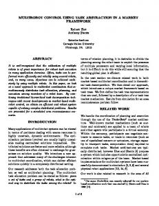
Figure 1 shows screen captures of the control interface as used in the presented experiment. Display elements not relevant to the experiments setup were removed to reduce distractions. The interface consists of two map displays (as depicted in Figure 1, section A and B) rendering the environment and other objects such as robots or waypoints using a 2-D, gods-eye perspective. The two displays render the same data at different levels of detail. While the smaller map referred by “A” (see figure 1 right for enlarged version) provides the operator with an overview of the entire operational area, the second display referred by “B” (see figure 1 section B, left) renders only a small rectangular section of the operational area at maximum detail level. The actual selection of the location to be rendered in display “B” can be done by positioning the half-transparent filled rectangle (see Figure 1 right) on display “A”. Environmental structures are depicted by black segments and objects, for example robots, are rendered as small coloured rectangles to indicate their location. B
In sp ectio n p o in ts (p u rp le)
A
R o b o ts
R o b o ts (red )
Figure 1: Screen Capture of Multi-Robot Control Interface (left). Enlarged Capture of Overview Map from Section A Displaying Entire Operational Area (right). RTO-MP-088
22 - 3
Design and Evaluation of a Multi-Robot Control Interface Display “B” is used to select and instruct the robots with the computer mouse as input device. Instructing the robot is done via a robot specific popup context menu allowing available commands to be executed. Available commands in the first experiment were: “Set path” to assign subsequent waypoints to the selected robot, “Delete path” to erase the entire path of the selected robot, “Delete last waypoint” to remove the waypoint entered last. In the second experiment, this set of commands was replaced by a single “Set Goalpoint” command. As a special command for both experiments “Inspection” was used to perform an inspection as will be described in section 3.4. Figure 2 shows an enlarged screen capture of a section of display “B” depicting environmental structures, the robot, a path, and an inspection point.
In sp ectio n p oin t
P a th
R obot
Figure 2: Section of Screen Capture of Display “B”.
3.3
Trials
For the experiment, we designed trials with three different numbers of available robots and two different environments. For the available numbers of robots we selected 2, 4, and 8. The implementation of the experiment ensured that there were at any time at least as many inspection points available as there were robots. The choice for the environments was based on the preference of real world indoor and outdoor maps to synthetically designed environments. Figure 3 left depicts our choice for an indoor environment based on a simplified floor plan (doors were removed).
Figure 3: Floor Plan and Industry Complex as Indoor and Outdoor Environment.
This environment is referred to as map “F” in the following text. Figure 3 right shows the second environment that is based on a large 20th century industry complex. This environment is referred to as map “B” in the following text. The choice of these two environments was motivated by their complexity and their structural and visual difference. 22 - 4
RTO-MP-088
Design and Evaluation of a Multi-Robot Control Interface This design leads to six trials for each subject based on having 2, 4, and 8 robots in combination with map “F” and “B”. These trials will be referred to by abbreviations like “F2” for the trial with 2 robots on map “F” or “B8” for 8 robots on map “B”. Each trial was 10 minutes 30 seconds long. Trial sequence was permutated for all subjects.
3.4
Training and Subjects
Subjects received a written instruction describing the relevant functionality of the interface and the tasks to be performed at least a day before trial. Prior to the experiments itself a supervised training was conducted using special training environments for practice. Eleven subjects from the staff of our institute participated in both experiments. None had prior experience with this interface but all had long-term experience in desktop computer use and were therefore familiar with using a computer mouse as input device. The time gap between the first and second experiment was about two months.
3.5
Dependent Variables
Operator actions and robot status were logged during the experiment and users were observed by the instructors to detect and record difficulties with the user interface. After each trial operators were asked to judge their workload level using the rating method ZEIS [1]. Performance measures about the operator’s ability to simultaneously control and monitor multiple robots were taken from the following variables: •
Number of executed inspections.
•
Parallel operation of robots. Number of active (non idle) robots per time unit (1 second) is observed and tracked.
•
Robot distance per executed inspection.
•
Inspection delay. The amount of time the robot is waiting at the inspection point until the operator executes the inspection.
4.0 RESULTS In this section, the results of the two experiments are presented. As previously mentioned the experimental design featured a control and a monitoring task where the control task was modified between the first and second experiment. The presentation of the results is therefore divided into three subsections with data about the control and monitoring task in the first two subsections followed by the subjective ZEIS rating in the third. For most results, bar graphs are used to depict their values. These graphs contain the results of both experiments with the solid bar being from the first and the patterned bar being from the second experiment. Bars are labelled “FBx”, “Fx” or “Bx” according to the trials from which their values were generated where “F” and “B” represent the two environments and “x” the number of robots (possible values are 2, 4 and 8). Where available bars have also the standard deviation interval displayed.
4.1 4.1.1
Control Task Number of Executed Inspections
The execution of inspections at inspection points represented the central task of the two experiments. Figure 4 depicts the results.
RTO-MP-088
22 - 5
Design and Evaluation of a Multi-Robot Control Interface
40
Executed inspections
35 30 25 20 15 10 5 0 FB2
FB4
FB8
F2
F4
F8
B2
B4
B8
Figure 4: Number of Executed Inspections.
Starting with the 2 robot trials the values of FB2, F2 and B2 are almost equal for both experiments. This indicates that operators did not benefit from the path planning support in both environments. A different result can be seen at the trials with 4 and 8 robots where the added support in experiment 2 led to an increase of between 20 to 50 percent in executed inspections. Notable is that the differences between the values of the trials with 4 and 8 robots do not differ highly in both experiments. The doubling of available resources led only to small increases or even decreases in the number of executed inspections indicating that the use of 8 robots instead of 4 did not yield a significant increase in executed inspections. This result appears in both experiments even though at a higher level in experiment 2. 4.1.2
Distance per Inspection
The distance per inspection represents the quotient of the total distance travelled by all robots and the total number of executed inspections. It yields information about the efficiency of the operators action planning. 450
Distance per inspection
400 350 300 250 200 150 100 50 0 FB2
FB4
FB8
F2
F4
F8
B2
B4
B8
Figure 5: Distance per Inspection.
It can be seen that throughout all trials there is a rise in distance per inspection with rising numbers of robots. Comparing both experiments, it is interesting to see that the trials with four robots produce almost equal values. Taking into account the results shown in figure 4 it can be concluded that the introduction of path planning support raised operator effectiveness in respect to the number of executed inspections and the distance travelled per inspection. A larger increase in distance per inspection can be seen between the trials of 4 and 8 robots. This is interesting since the number of completed inspections (Figure 4) in the corresponding trials is almost equal to the trials with 4 robots. This indicates that operator effectiveness with 8 robots was lower than with 4 robots in respect to these values.
22 - 6
RTO-MP-088
Design and Evaluation of a Multi-Robot Control Interface 4.1.3
Parallel Robot Operation
Throughout the trials, a robot can be either idly waiting for operator interaction or actively following a path. The parallel robot operation measures the accumulated activity of all robots in respect to the maximum possible accumulated activity. For example a value of 2 means that, the overall utilization of available robot resources is equivalent to the maximum utilization of 2 robots. 4 Average parallel operation
3,5 3 2,5 2 1,5 1 0,5 0 FB2
FB4
FB8
F2
F4
F8
B2
B4
B8
Figure 6: Average Parallel Robot Operation.
As expected the value for parallel robot operation rises with the number of robots available in both experiments. While in the first experiment only a small change between 4 and 8 robots can be seen the path planning support in the second experiment yields a large increase between 2, 4 and 8 robots. Comparing both experiments, the results for 2 robots are almost equal indicating that the path planning support had no impact on parallel robot operation. A remarkable result is that the levels of 4 robots in the second experiment are almost identical to the levels of 8 robots in the first. In the trials with 4 robots, a notable increase can be seen which is almost equal in both environments with 10% and 14%. A large difference of about 44% can be seen between 4 and 8 robots in the second experiment. This indicates that the path planning support had a significant impact on parallel robot operation. Operators were obviously capable of controlling higher numbers of robots in parallel. However viewing this result in respect to the number of executed inspections the higher degree of parallel operation did not help to increase inspections. Similar to the finding in the previous section operators appeared to be less effective with the use of 8 robots than with 4.
4.2 4.2.1
Monitoring Task Inspection Delay
It was the central task for the operator to use the available robots to carry out inspections at inspection points. This required the operator for each inspection point to instruct the robot to navigate to this point and then to execute the inspection. The inspection delay measures the amount of time the robot waits idly at the inspection point until the operator executes the inspection command. We believe that this variable indicates the quality of the operators monitoring.
RTO-MP-088
22 - 7
Design and Evaluation of a Multi-Robot Control Interface
Average inspection delay (ms)
120000 100000 80000 60000 40000 20000 0 FB2
FB4
FB8
F2
F4
F8
B2
B4
B8
Figure 7: Average Inspection Delay.
Throughout all trials, the inspection delay rises with the number of robots available to the operator with lowest delays in the two robot trials and highest delays in the 8 robot trials. Comparing both experiments, it can be seen that the path planning support yielded lower inspection delays consistently in the 2 and 4 robot trials with reductions of 29 and 42 percent. This indicates that for these trials the modification of the control task had a notable effect on the monitoring task. The results for the 8 robot trials are inconclusive as F8 and B8 show opposite effects. Whether this is caused by random error or other effects is yet unclear. Similar to the previous sections the highest effects between both studies can be seen in the trials with 4 robots with reductions of 44 and 41 percent. In addition, the point of lower operator effectiveness with 8 robots is supported as in the second study the increase of inspection time between the use of 4 and 8 robots is of 163 and 174 percent. This increase is significant compared to the marginal increase of executed inspections (see figure 4) in the corresponding trials. 4.2.2
Inspection Delay Development Over Time
The average inspection delay as depicted in figure 7 does not provide any information about the operators monitoring performance over time. In this section, the inspection delay is calculated as the average of the delay of all inspections performed within one minute. Displaying this value for each minute of the experiments time yields information about the development along the timeline. Figure 8 displays the raw results and logarithmic approximation with results from the first experiment (X1) as dotted line and from the second (X2) as solid line. 80000
70000
X1
60000
X2
50000
FB8
40000 30000
FB4
20000 10000
FB2
0 0
1
2
3
4
5
6
Tim e (m inute )
7
8
9
10
Average inspection delay (ms)
Average inspection delay (ms)
80000
70000
X1
60000
X2
50000
FB 8
40000 30000
FB 4
20000 10000
FB 2
0 0
1
2
3
4
5
6
7
8
9
10
Time (minute)
Figure 8: Inspection Delay Over Time. Raw Data (left) and Logarithmic Approximation (right).
From the left graph in figure 8 one can see that the trials with 2 and 4 robots (FB2, FB4) have a similar development: A rise of inspection delay time at the beginning of the experiment followed by the convergence of the delays. This is behaviour is displayed using logarithmic approximation in the right 22 - 8
RTO-MP-088
Design and Evaluation of a Multi-Robot Control Interface graph of figure 8. The 8 robot trials (FB8) show almost linear increase in inspection time. We believe that the 8 robot inspection delay times would converge also in longer experiments. From the data depicted in figure 8 we conclude that in the course of the experiment operators had increasing problems with monitoring multi-robot systems larger than two robots. The rise in the inspection delay times can only be caused by robots being “forgotten” by the operator and thus waiting very long periods until served. In the 2 robot trials (FB2) operators were well able to closely monitor both robots and thus achieved stable inspection delay values very early in both the first and second experiment. In comparison to this, the 4 robot trials (FB4) reach stable inspection delays only in the last third of the experiment while the 8 robot trials (FB8) show no indication of convergence over the whole experiment. Comparing the first (X1) and the second experiment (X2) both 2 and 4 robot trials (FB2, FB4) show reductions in inspection delay with highest absolute reductions in the 4 robot trials. The effect of the path planning support on the trials with 8 robots in the second experiment remains inconclusive. Both the raw data (Figure 8 left) and the approximation (Figure 8 right) display no clear effect. This on the one hand supports the point that operators were most effective with the control of 4 robots but on the other hand weakens it due to the much slower convergence and much higher values of the inspection delay in comparison to the 2 robot trials.
4.3
ZEIS Subjective Rating
9
9
8
8
7
7
6
6
Scale factor
Scale factor
After each trial subjects were asked to rate their workload. This sampling was done using the ZEIS subjective workload rating method. It requires subjects to perform two judgments in sequence. The first judgment is based on the three basic categories “easy”, “medium” or “difficult”. Subsequently the subject is graphically switched to more specific instructions and led to the appropriate section of the larger scale ranging from 0 (leftmost) meaning “very easy” to 10 (rightmost) meaning “very hard”. Figure 9 depicts two graphs containing the averaged ZEIS ratings from both experiments including standard deviation.
5 4
5 4
3
3
2
2
1
1 0
0 FB 2
FB 4
FB 8
F 2
F 4
F 8
B 2
B 4
B 8
2 robots
4 robots
8 robots
M ap "B "
M ap "F"
Figure 9: Subjective Evaluation with ZEIS.
As expected, the task difficulty rating is increasing with the number of robots in both experiments. While the difference between the 2 and 4 robot trials in each experiment is roughly 0.5 the difference between 4 and 8 robots is as large as 1 on the scale. This indicates that subjects experienced higher difficulty when in charge of managing 8 robots. As noted above this was expected but on the other hand the scenarios with 8 robots provide more possibilities for effective deployment than the scenarios with 2 or 4 robots. Comparing both experiments one can see a notable lower rating of the trials in the second experiment than in their counterparts from the first experiment. The right graph of figure 9 shows that the difficulty of managing 8 robots dropped in the second experiment to a level similar to the control of 4 robots in the first experiment. Finally, an unexpected result was the similarity in ratings for both maps “B” and “F”. Although the two maps are visually and structurally quite different, this appeared to have no impact on the subjects rating. This similarity can be seen in both experiments (Figure 9 right).
RTO-MP-088
22 - 9
Design and Evaluation of a Multi-Robot Control Interface
5.0 CONCLUSION AND FUTURE WORK In this paper, we presented two subsequent studies with our multi-robot control interface. Our primary interest was to gather user feedback about the usability of the current development stage of our interface. This user feedback as well as observations about difficulties that users experienced with the interface are analysed to guide and support the ongoing development process. Furthermore, we were interested in gathering data concerning the problems associated with the simultaneous management of multiple semiautonomous robots. Apart from a number of minor problems associated with the task specific handling of the interface like a more efficient path management system a few major deficiencies of the interface could be identified: •
Lack of capability to address and control multiple robots at once. In multi-robot scenarios, the need to address sets of robot is frequently required.
•
Lack of context switching support. When managing multiple robots the operator needs to be able to frequently switch between the robots and their respective informational context.
•
Stack of visited contexts. When frequently switching context between multiple robots users often requested a possibility to return to a context just previously visited.
Our observation of the operators during the experiments and their feedback indicates that a multi-robot control interface requires specialized and dedicated support for the simultaneous management of multiple autonomous mobile robots. The two studies yield immediate information supporting the user interface development process. The performance results and subjective ratings indicate that subjects were best able to supervise between four and five robots. The trials with 8 robots indicate a reduction in performance. From our observation throughout the trials, we often saw subjects trying to use all their available resources all the time resulting in inefficient behaviour. For our user interface, this means that the layout will be based on the requirement to display the status information of at most four to five robots simultaneously. In the introduction, we outlined that autonomy on the robots side is a requirement to enable operators to control and monitor a multi-robot system. In the task design of the two experiments presented in this paper, we divided the supervision task into a control task for the navigation of the robots and a monitoring task for the inspection. In the second experiment, the control task was modified by using an automated path planning function representing an increased degree of autonomy on the robot’s side. From the comparison of the data from both experiments, we can conclude that the impact of autonomy on the operator’s performance must be viewed separately for the control and the monitoring aspect. In the case of our experiments, the only autonomy available was realized within the robots navigation routine. Based on the results of section 4.1.3 we can conclude that the use of the path planning function increased the overall parallel robot operation due to the reduction in steps to perform robot navigation. Taking into account the increase in executed inspections in the second experiment (section 4.1.1) we can conclude that the increased degree of autonomy raised the control efficiency of the operator. Analysing the monitoring aspect represented by section 4.2 an obviously similar picture appears. In the case of 2 and 4 robots a notable reduction in inspection delay times was achieved in the second experiment thus the operator’s monitoring was positively affected. But comparing the approximated levels of inspection delay times in figure 8 (right) at the minutes 8, 9 and 10 between 2 and 4 robots there is approximately a three to four fold difference in both experiments respectively. Therefore, we suspect that the impact of the higher degree of autonomy on the monitoring performance was based on a higher context-switching rate of the operator due to faster execution of robot navigation. Following this argumentation the higher degree of autonomy in the second experiment increased the quantity of robot resources a single operator is able to control but did not support his monitoring ability. We believe that the operator’s ability to monitor complex systems requiring autonomous components represents the actual bottleneck in human robot teams. Taking into account the data from the trials with 8 robots we can see large overall increases in 22 - 10
RTO-MP-088
Design and Evaluation of a Multi-Robot Control Interface quantity (see section 4.1.3) but even though operators were able to control all these robots they were clearly unable to keep track with the overall situation as the inspection delay times in figure 8 (right) show. From this finding, we conclude that without sophisticated operator support supervising multi-robot systems larger than two robots is very hard to realise if tight monitoring is required. The next step in our work is consequently the introduction of operator support into the multi-robot control interface. Further, we will use more sophisticated methods to track and analyse operator actions. Before validating these results with our real world multi-robot system, we will conduct another sequence of simulation-based experiments with the introduction of system failures and other events requiring operator interaction.
6.0 REFERENCES [1]
F.D. Pitrella and W.-D. Käppler “Identification and Evaluation of Scale Design Principles in the Development of Sequential Judgment, Extended Range Scale” Bericht Nr. 80, Institut für Anthropothechnik, Wachtberg, 1988.
[2]
C. Pfendler “Vergleichende Bewertung des NASA-TLX-Skala und der ZEIS-Skala bei der Erfassung von Lernprozessen” Bericht Nr. 92, Institut für Anthropotechnik, Wachtberg, 1992.
[3]
R. Simmons, D. Apfelbaum, W. Burgard, D. Fox, S. Thrun and H. Younes “Coordination for MultiRobot Exploration and Mapping”, in Proc. of the National Conference on Artificial Intelligence (AAAI), 2000.
[4]
W. Burgard, M. Moors, D. Fox, R. Simmons and S. Thrun “Collaborative Multi-Robot Exploration”, in Proc. of the IEEE International Conference on Robotics & Automation (ICRA), 2000.
[5]
M. Moors “Koordinierte Multi-Robot Exploration”, Diplomarbeit in der Abteilung III des Instituts für Informatik, Bonn, 2000.
[6]
F.E. Schneider and D. Wildermuth “Motion Co-ordination for Formations of Multiple Mobile Robots” in Conference Transcript of the Conference on Field and Service Robotics, Helsinki, Finland, June 2001.
[7]
F.E. Schneider, D. Wildermuth and H.L. Wolf “Concept of a Man-Machine-Interface for a HumanMulti-Robot-System” in Conference Transcript of the International Conference on Mechatronics and Robotics, St. Petersburg, Russia, May 2000.
[8]
T. Fong, S. Grange, C. Thorpe and C. Baur “Multi-Robot Remote Driving with Collaborative Control”, in Proc. of the IEEE International Workshop on Robot and Human Communication, Bordeaux, Paris, France 2001.
[9]
M.A. Goodrich, D.R. Olsen Jr., J.W. Crandall and T.J. Palmer “Experiments in Adjustable Autonomy”, in Proc. of IJCAI01 Workshop on Autonomy, Delegation and Control: Interaction with Autonomous Agents, Seattle, Washington, USA, August 2001.
[10] EUROCONTROL “Situation Awareness, Synthesis of Literature Search”, in EUROCONTROL Report, December 2000. [11] M.R. Endsley and D.B. Kaber “The Use of Level of Automation as a Means of Alleviating Out-of-the-Loop Performance Problems: A Taxonomy and Empirical Analysis”, in Proc. of the 13th Triennial Congress of the International Ergonomics Association (pp. 168-170).
RTO-MP-088
22 - 11
Design and Evaluation of a Multi-Robot Control Interface [12] D.B. Kaber, E. Onal and M.R. Endsley “Level of Automation Effects on Telerobot Performance and Human Operator Situation Awareness and Subjective Workload”, In Automation Technology and Human Performance: Current Research and Trends, M. Scerbo and M. Moulana (Eds.), Lawrence Erlbaum Associates: Mahwah, NJ, 1998, pp. 165-170. [13] M.R. Endsley, D.R. Kaber and E. Onal “The Impact of Intermediate Levels of Automation on Situation Awareness and Performance in Dynamic Control Systems”, in Global Perspectives of Human Factors in Power Generation. Proceedings of the 1997 IEEE Sixth Conference on Human Factors and Power Plants, D.I. Gertman, D.L. Schurman and H.S. Blackman (Eds.), IEEE, New York, 1997, pp. 7-7,7-12. [14] D.B. Kaber and M.R. Endsley “The Combined Effect of Level of Automation and Adaptive Automation on Human Performance with Complex Dynamic Control Systems”, in Proc. of the 41st Annual Meeting of the Human Factors and Ergonomics Society, Santa Monica, CA, 1997, pp. 205-209. [15] B.A. Trouvain, F.E. Schneider and D. Wildermuth “Integrating a Multi-Modal Human-Robot Interaction Method into a Multi-Robot Control Station”, in Proc. of the IEEE International Workshop on Robot and Human Communication, Bordeaux, Paris, France 2001.
22 - 12
RTO-MP-088