International Conference on Mechanical, Industrial and Energy Engineering 2010 23-24 December, 2010, Khulna, BANGLADESH
MIE10-104
Design and Implementation of a Linear IC Based Low Cost Digital Tachometer for Laboratory and Industrial Application S.M.Ferdous1, Mohammad Rokonuzzaman1, Sayedus Salehin2, Arifa Ferdousi3, Tanvin Hossaine3 1
Department of Electrical and Electronic Engineering, Islamic University of Technology, Board Bazar, Gazipur - 1704 BANGLADESH 2 Department of Mechanical and Chemical Engineering, Islamic University of Technology, Board Bazar, Gazipur - 1704 BANGLADESH 3 Department of Electronics and Telecommunication Engineering, Prime University, Dhaka – 1216, BANGLADESH
ABSTRACT A digital tachometer can provide more accurate and precise reading than an Analog tachometer. Any adjustable speed drives uses an incremental shaft encoder or a sensor and an electronic circuit for rpm as well as velocity estimation. The usual method of counting pulses generated by encoder or sensor in a fixed period of time produces a high precision velocity or rpm estimate in the high speed range. Tachometer plays a vital role in measurement of rpm of any rotating device and it is essential for any control system especially in servomechanism. Most of the controllers employed in the industry to control industrial process use a tachometer which gives the provision of feedback in a control circuit. The purpose of the project was to develop a digital tachometer using low cost linear digital ICs those are readily available in the markets of Bangladesh. This tachometer can be easily used for both industrial and laboratory purposes where it should be able to measure rpm and provide a voltage proportional to the speed of the shaft of the rotating device. At the same time efforts have been taken to reduce the cost of the tachometer as much as possible. Keywords: Tachometer, Speed Measurement, Frequency to voltage converter, Position and Velocity Feedback, Sensor
1. Introduction The need of a tachometer arises for measuring and controlling of any rotational devices. It is an essential component in the design of the feedback loop in the speed control of ac and dc drives. Introducing a velocity feedback using a tachometer in any servo controlled system greatly influence the stability of the system. In a closed loop controller the use of tachometer is of immense important as if is the most convenient way of producing a feedback proportional to the speed of the shaft. D.C. tachometers are widely used due to their good dynamic performances. But digital tachometers are preferable due to its better accuracy, no A/D conversion, less maintenance (as they are brushless) and noise immunity [1]. Speed measurement techniques are thoroughly reviewed in [2] and [3]. A digital tachometer works on the principle of frequency measurement which has two distinct approaches which are – (1) Measurement of elapsed time between successive pulses.[4] (2) Counting the number of pulses in a fixed period of time.[5] Some advanced techniques and methods have been proposed to obtain better accuracy and response time. The constant speed elapsed time (CET) proposed in [6], a combined method which uses both pulse counting and elapsed time was proposed [7] and finally the double buffered method [3], [8] uses an approach which avoids the synchronization of the incoming pulse and performs a * Corresponding author. Tel.: +88-01719338349 E-mail address:
[email protected]
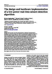
multiplication of the incoming frequency for fast response time. Considering the fact that the tachometer is to be implemented using digital ICs, method (2) is chosen and implemented with a set of ICs whose block diagram is shown in Fig 2.1. Other advanced methods including software and hardware observers are discussed [2] and they require a complex microprocessor or microcontroller based circuits. It should be mentioned here that this system works with moderate accuracy and precision which males it suitable for DC servo-controlled system. But in case of high precision wide speed range like the case for indirect vector controls of induction motor [1] this design may not be suitable. The meter can measure rpm in between a range of 0 to 14985 rpm or 0 to 999 rps (rotation per second). Different types of tachometers are available in Bangladesh. But most of the times they failed to meet the desired criteria of the users. In designing the closed loop controller of different types of motors (specially is in servomechanism and position controlling system.) a tachometer can be a good choice rather than any other feedback elements. The available tachometer in the markets of Bangladesh is quite expensive. At same time the precision and accuracy are less. Moreover most of the tachometers, specially the digital ones, do not have the provision of feedback. That is why a custom digital tachometer is developed using commercially available IC’s. It can be used for both measuring the shaft speed and also it can produce a voltage proportional to it using a Frequency to voltage converter. This voltage can be MIE10-104-01
processed and used as a feedback in any closed loop controller. As we have used general and commercially available ICs the cost of the meter has been greatly reduced. At the same time the accuracy and reliability is increased as a digital system is more precise than any analog system. This paper is organized as follows. Section 2 presents the basic principle of operation of the measuring system. In Section 3 a detailed description of the components and devices are discussed. The hardware implementation using all the components is presented in detail along with all the control signals. Section 4 is devoted to the technical and Economical analysis of the meter and finally, in Section 5 some conclusions and future work are drawn. 2. Principle of operation A simple method to measure rotational speed is to count the number of shaft rotation during given period of time. The resulting count will be directly proportional to the shaft speed. The shaft speed in revolution per minute is related to the displayed pulse count by
r. p.m =
time it triggers the latch ON so that the counted pulses are fed to the display. A seven segment decoder driver is needed to operate the display. The LED decoder and driver converts the latched BCD count into seven signals required to drive the display. The display shows the number of pulses that have occurred during the counting period. Finally a frequency to voltage converter is employed for designing a circuit which generates voltage proportional to the speed of the shaft. This voltage can be processed for providing feedback in any kind of controller circuits.
And Gate
Q Timer
pulse count r . p .m = × 60 = pulse count × 15 4 A sensor will sense the rotation of the shaft and it will generate pulses which will be counted by the timer. A capacitive proximity sensor is used to count the shaft rotation. Each time the shaft passes the sensor, the Schmitt trigger provides as single pulse to a counting circuit. A circuit is needed to count and display the pulses over a given interval of time T, set by the timer. The decade counter counts the pulses and is controlled by a controller The flip flop changes state each time when a negative going output is received from the timer. The timer is set at T= 1 second and the output of the flip flop is alternately at logic High for 1 second and at logic Low for next one second. Consequently the AND gate is alternately enable for one second and disabled for one second. During the time the AND gate is enabled the Schmitt trigger output triggers the counter. The exact number of input pulses is counted during the period T=1second which is a measure of pulse generated per second. The counter is reset by the flip flop and the Monostable Multivibrator. Just prior to counter reset the output is stored by a latch circuit which is enabled by the flip flop and the Monostable Multivibrator. The latches are necessary to hold the previous count for display while the counter begins a new count cycle. The output Q is used for resetting the counter and enabling the latch. This ensures that when counting is in progress nothing passes through the latch. At the end of counting
T
L Q
R
pulse count /ppr × 60 T
Where, ppr is the num of pulses per revolution generated by the sensor. Here the sensor will generate four pulses for one revolution of the shaft. We set the counter with counting period T= 1 second. So,
Schmitt Trigger
Sensor
Dual One shot Retriggerable Monostable Multivibrator
Counter Reset Control
Decade Counter
Decade Counter
Decade Counter
Decade Counter
Latch
Latch
Latch
Latch
BCD to 7Segment Decoder
BCD to 7Segment Decoder
BCD to 7Segment Decoder
BCD to 7Segment Decoder
Display
Display
Display
Display
Trigger Input
Fig 2.1: Block diagram of a Digital Tachometer. The sensor generates pulse waveform for counting. The pulses are counted over a precise time period generated by the timer. The resultant display can be read as rotation per second 3. Components and Devices Components and devices those are required to develop the system are enlisted and a brief description of them is covered in this section. The whole system can be divided into five distinct subsystems. They are – • Sensor and Speed Measuring Block • Timer • Counter and display unit • Counter Controller • Frequency to voltage converter. 3.1 Sensor and Speed Measuring Block The sensor part of the circuit is made using a capacitive proximity sensor (M12), Opto-isolator (H21A1) and a Schmitt trigger (7414). A capacitive proximity sensor can detect the present of materials like plastic, wood, cardboard, paper and non ferrous materials. Typical MIE10-104- 2
sensing distance is 10 mm to 50 mm. The shaft is embedded with four equidistant plastic strips. Each of the strips is situated at an angle of 90 degree from each other. So, one full rotation of the shaft would cause the sensor to generate four pulses. The sensor will drive an opto-isolator circuit which in turn will generate a train of square pulses via a Schmitt trigger. The number of generated pulses will be proportional to the shaft speed. The circuit diagram is shown in fig 3.1.
retriggerable one shot monostable multivibrator is triggered by Q to generate the latch control signal L of length ∆T. The trailing edge of the latch pulse triggers the second one shot which is negative edge triggered and it produces a delayed reset pulse R for the counter. The pulse width is given by the formula, ∆T= 0.28 ×Rx × Cx2 (1+ 0.7/Rx) nanoseconds Let, Rx = 147 kΩ and Cx= 1 µF So, ∆T= 41.35 ms Timer output
1 HZ
Q
Q
Fig 3.1: Schematic Diagram of the sensor circuit. The opto isolator generates pulses as the shaft moves over the proximity sensor. The generated pulses are fed to a Schimitt trigger for smoothing. The output of the Schimitt trigger is the number of pulse generated that resembles the rpm of the shaft.
L 141.35ms
R
3.2 Timer A simple 555 timer is used in astable mode to generate a waveform of 1 Hz which will give a time period T = 1 second. Timer output will trigger the flip flop which in turn controls the counter and the latch circuit.
141.35ms
Fig 3.3: Latch control and reset control signal of the counter. They are used to reset the counter and the latch respectively.
Q
Fig 3.2: Circuit Diagram of the Timer circuit. It generates a square pulse train of 1 Hz frequency. It provides the necessary clock pulse for all the ICs. 3. Control and Display Unit A counter circuit is needed to count and display the pulses over a given interval of time. The 7490 decade counter counts the pulses and is being reset by a negative going reset control signal at an interval of one second so that it will be ready to count the next incoming pulses. Just before the reset action the output is stored by 7475 data latches those are enabled by a brief pulse called latch control signal. The latches are necessary to hold the previous count for display while the counter begins a new count cycle. A 74123 dual
Fig 3.4: One shot monostable multivibrator circuit to generate latch control signal (L) and Counter reset control signal (R). External resistor and capacitor are used to generate the signals having pulse width (∆T)