Proceedings of Third Biennial National Conference. NCNTE- 2012. Feb 2.•-25
Design and Implementation of Driver Circuit for High Power LED Mini Rajeev Department of Electrical Engineering Fr.C.Rodrigues Institute of Technology, Navi Mumbai, Maharashtra,India. minirajeev
[email protected]
Sreedevi Sanjeev Nair Department of Electronics and Telecommunication Fr.C.Rodrigues Institute of Technology, Navi Mumbai, Maharashtra,India.
[email protected]
Abstract-This
paper discusses a high power Light Emitting Diode (LED) driver based on buck converter, to drive a series of hlgh power LEOs. The input is from a 24V battery which is charged from a Photovoltaic panel. Besides simulation, a laboratory prototype of driver for 8W LED is designed, implemented and tested. Experimental results verify the validity of designed driver circuit.
Keywords-buck-converter;LED;driver
I.
circuit;
energy costs. LED light bulbs are not sensitive to frequent "on/oft" power cycling, which can bear at least 15,000 cycles [3]. This paper deals with the design and implementation of high power 8W LED driver circuit. A battery of24 V is used as a source for 12V, 8W LED lamp with the help of' buck converter controlled by micro-controller. The intensity of the LED lamp will be kept constant by sensing the current of the lamp using the feedback loop through the microcontroller to the switch in the buck converter so as to adjust the duty cycle of the switches. Simulation and Hardware results are presented.
PICI6F877A
INTRODUCTION
Energy management and cost reductions playa key role in enhancing the economic productivity. As a result, energy costs now constitute a major component of operating funds. Lighting in a typical telecom building constitutes about 25% of the energy bills [I]. There is a considerable scope of reducing energy consumption through energy efficient lighting schemes. However, the experience shows that there are barriers in providing energy efficient lighting schemes due to high capital cost, lack of knowledge and good quality products. Lighting era has undergone a remarkable changes from incandescent bulbs, halogen lamps, Compact Fluorescent lamps (CFLs) and now to various types of LEOs. It is seen that the electricity used over the lifetime of a single incandescent bulb costs 5 to 10 times the original purchase price of the bulb itself .CFLs contain small amounts of mercury which is a toxic metal. This metal may be released if the bulb is broken, or during disposal. CFLs are sensitive to frequent on/off cycling. Their rated lifetimes of 10,000 hours are reduced in applications where the light is switched on and off very often. The halogen bulb can have twice the life of an incandescent and use the same amount or slightly less electricrty. Halogens are more expensive than CFL bulbs, but less expensive than standard fluorescent bulbs[1,2].
II.
NEED FOR DRIVER CIRCUIT
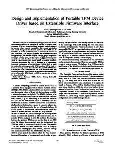
With ever demanding for higher brightness LED and higher power efficiency especially for portable power application, there is trend for major IC component manufacturer to introduce more advance switching LED current control driver with various functionality and better current matching or regulation. LEOs are current-driven devices whose brightness is proportional to their forward current Fig.! shows that a small change in forward voltage produces large change in forward current. As LED's heat up, the increased current results in additional heating at the junction. If nothing limits the current, the junction will fail due to the heat. This is termed as thermal runaway which is the main problem with high power LED's[3]. Forward Current can be controlled in two ways. The first method is to connect series resistor along with the lamp. The drawback of this method is the voltage drop and power dissipation across the resistor, thereby leading to overheating of the LED's and reduction of battery life. The second, preferred method of regulating LED current is to drive the LED with a constant-current source. The constant-current source eliminates changes in current due to variations in forward voltage, which translates into a constant LED brightness. Multiple LED's should be connected in series configuration to have an identical current flowing in each LED. Driving LED's in parallel requires resistor in each LED string which lowers the efficiency and uneven current matching [2].
LED's are free of mercury. Hence, they can be safely disposed of with no worries of contaminating the environment. The life of LED is about 50,000hours which is 4 to 8 times that ofa CFL light bulb. LED's save in energy costs, as well as maintenance and replacement costs. LED bulbs generate- very little heat transferring most of their energy directly into light, eliminating excessive heat buildup that can adversely affect
46
Proceedings of Third Biennial National Conference. NCNTE· 2012. Feb 24·25
2800
-Pure
White I
BATTERY
I
BUCK CONVERTOR
LED LAMP
~ 2450 ct
oS
2100
.,.." 1750 ::s
I
U
"e 1400 •• ~ 1050 0 01
-c
700
1/
350
o
0.0
PIC16F877A
/ /
...
., ••.,.. >
SENSED CURRENT
PWM
'"
Figure 2. Generic Block diagram of the system
/ 05
1.0
1.5 Forward
2.0
2.5
Vottaol!
3.0
3.5
40
4.5
rVl
Figure 1. LED Average forward current vis forward voltage relationship
III.
DESIGN AND SIMULATION
Fig 2 .shows the generic block diagram of the system. A battery of 24Y is used to charge the 12 Y, 8W LED lamp. A buck converter is chosen between the battery and the lamp in order to step down the voltage. The intensity of the lamp is kept constant by sensing the current from the lamp through the comparator circuits to the microcontroller. Figure 3. Simulation of 8W LED lamp driver circuit
The equations and designed values of Land C for the buck converter is given in Table.!, where duty cycle(D)=50%,Ts=25KHz has been selected for the design. The microcontroller generates the PWM which is given as the trigger to the switch of the buck converter. The microcontroller PICI6F877A is chosen as it has inbuilt PWM outputs and has an ADC circuit. The PWM output is taken from PIC is fed to a MOSFET which has been selected to provide switching frequency of 25KHz. This output from the PIC controller circuit is fed through the buffer IC 74LS244 to the gate of the MOSFET of the buck converter.
TABLE I: DESIGNED VALUES OF L AND C FOR BUCK CONVERTER. Parameter L C
As shown in the simulated model of Fig. 3, in order to make the intensity of the LED lamp light constant, the lamp light is continuously measured and compared with reference using OPAMPs with the suitably adjusted gain which will be given as the inputs to the PIC controller to generate the required PWM. Fig. 4.shows the PWM output of the simulated circuit. The code is written in MikroC software to generate the PWM output. The code is written in such a way that if the intensity of the lamp decreases in comparison with the reference then the duty cycle will be increased while if the intensity matches the set value, the duty cycle will remain unchanged. The reference value of current is O.66mA for the connection of two parallel strings consists of four LED's in series as shown in Fig.5.
Equation (I·DlT, R 2
T,'(\.D\V. 8t>V.L
Value \Mh 2S"F
Figure. 4 . PWM output of the simulated circuit
47
Proceedings of Third Biennial National Conference, NCNTE- 2012. Feb 2.J-25
Figure 6, PWM output of the Hardware implemented circuit
•
Figure 5, Two parallel strings consists offour LED's
IV_
HARDWARE
SIMULATION
A 8W LED lighting system has been set up, and the topology and parameters of the main circuit is the same as the simulations. Power MOSFETs are used as switches and the switching frequency of the system is 25 kl-lz, The code for PWM program has been written in MikroC which was burnt into the PIC 16F877 A to generate the pulses. Fig. 6.shows the PWM output of the hardware implemented circuit This output from the PIC controller circuit is fed through the buffer to the gate of the MOSFET switch of the buck converter- The inductor used in the buck converter circuit which is I mH is of higher power handling ability. It is wound manually on the bobbin according to design with 30 turns [5]. In the feedback loop, to measure the current of LED lamp, a In resistor is used to get the corresponding voltage drop. The measured voltage value being insufficient has to be amplified with the help of the amplifier.
Figure
7,Hardware implementation of the driver circuit without the lamp.
To avoid the loading effect on the MOSFET,buffer amplifier has been also provided for stability. The comparator will select RAo pin or RAJ pin of the PIC controller depending on the high or low value of the current measured. The OPAMP's LM358 has been selected to function as comparator and buffer in the implementation.Fig.7. shows the hardware implementation of the circuit without the lamp. Fig.8.shows the 8W LED lamp used for this project Thus, the voltage required to illuminate one string was 12V_Fig 9. shows the 8W LED lamp along with its driver circuit The total cost incurred in the making of this circuit has been Rs_IOOO approximately where the luminaires, high power LED's, PIC controller contributed to the major cost The circuit was implemented and tested for 8 hours continuously with the constant lamp intensity.
Figure 8, 8W LED lamp
48
Proceedings of Third Biennial National Conference. NCNTE- 2012. Feb 24-25
REFERENCES [I)
www.VIRIBRIGHT.com
[2)
www.ecogeekliving.com
[3)
Michael day,"LED driver Consideration",Power Instrument co. operated. www.lc-Ied.com/articleslledlights.html
[4]
Figure 9. 8W LED lamp with its driver circuit
V.
CONCLUSION
A high power 8W LED lamp driver prototype has been successfully designed, constructed and tested. The main focus of developing this prototype converter is to investigate the possibility of its integration with solar PV panel. The prototype when implemented with large scale PV integration would prove to be more economical solution. Moreover, in future the cost of LED's will go on decreasing due to the advances in the technology of manufacturing process of LED's. The second area of investigation will be to develop and perform a full thermal circuit analysis to appropriately design the thermal management system. This thermal management system is required in order to demonstrate the technology at more relevant power levels.
Management.Texas
[5]
L.Umanand,SR.Bhat,Design Mode power converters,2nd
of magnetic Components for Switched ed., vol. 2. India: 1992, pp.82-85.
[6)
].E.I and O. Rivera, "Maximum Power Point Tracking using the Optimal Duty Ratio for DC-DC Converters and Load Matching in Photo voltaic Applications," IEEE, pp. 987-991,2008.
[7)
www.lightsearch.com/resourcesllightguideslformulas.html
[8]
J.PBenner, "Photovoltaics gaining greater visibility" Vo1.36, Issue 9, Sep. 1999, pp. 34-42.
[9]
S.Mekhilef, "Performance of grid connected inverter with maximum power point tracker and power factor control," International Journal of Power Electronics, vol. I, pp. 49-62,2008
[10)
R. W. Erickson, D. Maksimovic, Fundamentals of Power Electronics, 2ed., Kluwer Academic Publishers, 2001
IEEE Spectrum,
[II]
Feng Bo, Zhao Zhengming, Zhag Yingchao, Zhou Dejia, and Yuang Liqiang," Intelligent Controller for LEOs Lighting Systems Supplied by Batteries", IEEE Vehicle Power and Propulsion Conference (VPPC), September 3-5, 2008 [12] Mari Ochiai Holcomb, Regina Mueller-Mach, Gerd O. Mueller,Dave Collins, Robert M. Fletcher, Daniel A. Steigerwald, et al,"The LED lightbulb: are we there yet? Progress and challenges for solid state illumination," in IEEE Conference on Lasers and Electro-Optics, Taipei, China, 2003, 4pp. [13] Y. K. Cheng, and K. W. E. Cheng, "General study for using LED to replace traditional lighting devices," in IEEE International Conference on Power Electronics Systems and Applications, Hong Kong, China, 2006, pp. 173-17 [14] Yang Heng, Design of LED lighting converter and examples. Beijing: China Electrical Press, 2008. [15] Shogo Kitano, Shinichiro Haruyama, and Masao Nakagawa,"LED road illumination communications system," in IEEE Vehicular Technology Conference, 2003, pp. 3346-3350. [16] R. Faranda and S. Leva, "Energy Comparison of MPPT techniques for PV Systems," WSES Transaction on Power Systems, vol. 3, pp. 446455,2008.
49
----