2015
International Symposium on Advanced Computing and Communication (ISACC)
Design and Implementation ofFOPID Controllers by PSO, GSA and PSOGSA for MagLev System Prasanta Ro/, Manashita Borah2,
Lalbahadur Majhe, Nikita Singh4
Department of Electrical Engineering, NIT Silchar
Department of Electrical Engineering, NIT Silchar
Silchar, India
Silchar, India
[email protected],
[email protected]
[email protected] ,
[email protected]
Abstract-This paper puts forward the design of PID and FOPID controllers
along
with
its
validation
through
hardware
implementation in the Maglev system. The purpose of this work is not only to stabilize a ferromagnetic ball but also to control its position to track a reference signal. The designs have been carried
out
using
Gravitational
the
Search
optimizing Algorithm
algorithms (GSA),
namely,
Particle
the
Swarm
Optimization (PSO) and a hybrid of both the algorithms i.e. PSOGSA. The experimental set up is manufactured by Feedback Instruments
(Model
No
33-210).
The
experimental
results
obtained using a wide variety of test signals prove that the hybrid algorithm PSOGSA is better than its individual counterparts with satisfactory transient and steady state responses and also the performance of FOPID is an improved one compared to that of PID. Keywords-Magnetic levitation; P1D; FOP1D; Particle Swarm
I.
INTRODUCTION
optimization based
fuzzy logic [6, 7], neural adaptive control
[8]
mode control
[10, 11], [13],
[5],
have been used
in Maglev system. Whereas, feedback linearization [9], sliding
control
[12],
identification
[10],
back-stepping control
[14],
FOPID control
quantitate
feedback
theory
[15]
H infinity real
time
etc. are some of the
advanced control techniques that have been applied too.
Literature review revealed that fractional order controllers are
relatively less explored in controlling Maglev system. This
motivates the authors to propose a new FOPID controller tuned by PSOGSA to control the Maglev System.
D. Tuning Algorithms (PSO, GSA and PSOGSA)
ferromagnetic
object
against
gravitational
forces
in
the
presence of an electromagnetic field. This concept has found
versatile use in various modern applications like superfast
magnetic trains, high- precision platforms, magnetic lift etc. Its advantage lies in the fact that it can eliminate losses arising
due to mechanical friction. Based on the measured and desired
position of the levitating object, controllers are designed to
control the current through electromagnetic coil to generate the required force to control its position
[1].
B. Brief description about proposed controllers The PID controller is undoubtedly the most popular
controller in the industries owing to its convenience in design,
cost effectiveness, and acceptable robustness. However its
performance can still be improved by making the order of derivative and integration fractional terms.
Fractional order
controllers provide more alternatives and tlexibilities in design
but also introduce some challenges. A brief modern history of fractional calculus is given in
[2].
In
[3]
a FOPD controller is
designed using Firefly Algorithm and compared its improved
performance with that of a PID.
literature
for
Maglev
subsequently Jiang dispatch problem in
et.al [20].
20 I 0 [19],
and
used PSOGSA in economic load
E. Prime Objectives of this Work Prime objective of this work is to design PID and FOPID controllers considering the exact nonlinear model of Maglev system. The fractional order controller is difficult to design by classical method because of complexity of fractional order calculus. So controllers are designed using three meta heuristic algorithms
namely
PSO,
GSA and
PSOGSA.
Controller
implementation is done through Hardware in Loop (HIL) configuration. Step change, square wave signal, and sine wave signal is used as reference signals to test the effectiveness of the proposed controllers. II.
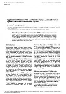
MAGNETIC LEVITATION SYSTEM DESCRIPTION
The basic setup of the Maglev system manufactured by
Feedback Instruments (Model No
33-210
is shown in Fig. l.
The main components are an optoelectronic position sensor,
electromagnetic actuator coil and a suspended ferromagnetic (HIL) configuration putting the desktop computer in the loop
Various control strategies and tuning algorithms have been in
with the combination of PSO and GSA in
ball. Controller is implemented through Hardware in Loop
Literature Review for Maglev System
reported
based evolutionary computation algorithm proposed by Kennedy and Eberhart [16, 17], inspired from social behaviour of bird flocking. GSA is a meta heuristic optimization method proposed by E. Rashedi et al in 200 9 [18], inspired from Newton's gravitational law. A novel hybrid population-based algorithm (PSOGSA) was proposed
Basic principle of the System The principle of the Maglev system is levitation of a
e.
[4],
intelligent control schemes such as the modified PSO
PSO is a swarm
Optimization; Gravitational Search Algorithm
A.
controllers like PID was designed in
system.
978-1-4673-6708-0/15/$31.00 ©2015 IEEE
Conventional
with actual hardware. Optoelectronic sensor determines the
vertical position of the ferromagnetic ball and passes it to
controller through an interface of Advantech card. Based on the
difference
between
desired
and
measured
ku2 .. mx=mg-- x2
output,
controller sends current to the actuator. Actuator consists of an
electromagnet wrapped up by copper wire 012850 turns on a
V = 142.86x-135.86
high permeability cylindrical iron core to generate upward attractive force on the ferromagnetic ball for levitation against
IV.
gravity. A suitable controller is needed to be designed to adjust current through the actuator to stabilize the levitated
ball and to make it follow a reference trajectory. The levitated
object is a hollow ball with mass of 20 g and diameter of 50
mm [4].
(1) (2)
DESIGN AND IMPLEMENTATION OF CONTROLLERS
A. PlD and FOPID Controller dynamics The dynamic equations of PID & FOPID controller are
given in (3) and (4) respectively with usual notations. The parameter
Ie
and I-t stands for the fractional order of integration
and derivative, respectively.
de(t) Kre(t) + KJ 'fe(t)dt + KD = u (t) dt "
(3)
--
B. Performance Index of Controller Performance Index (PI) is a quantitative measure to depict the performance of a controller. The PI adopted in this paper is ISE for all optimization algorithms, given in (5).
f
�
J=ISE= e2(t)dt; C.
(5)
Tuning of PID and FOPID Controller using PSO
The objective in PSO-based optimization is to seek a set of PID and FOPID parameters such that performance index minimized. The particles in PSO are a set of K JJ for PID and
particle's Fig. 1: Magnetic Levitation system (Feedback 33-210) III.
MODELLING BY MAGLEVSYSTEM
The dynamics of the Maglev system is governed by eqn. 1 where
m,x,g,k and u are mass of the ball,
position of the ball
measured from the electromagnet, gravitational acceleration,
electromagnetic coil constant and coil current respectively.
V are
Vi (t) and
A,
andf.1
position
K J and
for FOPID. A
Xi (t) are
updated
according to (6) and (7) respectively. A particle's new velocity
(XPi(t))
of its current position from its own best experience and the group's best experience
(XGb (t)) to
determine the
next direction of search, thereby narrowing the search space
Vi(t + I)=W,Vi(t) + c, .randO· (XPi(t) -Xi(t) ) + c .randO· (XGb (t) -Xi(t)) 2 Xi(t + 1) =Xi(t) + Vi(t + 1)
[16, 17, 19, 20].
position of the ball
and the corresponding sensor voltage respectively. The whole
Maglev control system can be represented by the simple block
diagram as shown in Fig. I.
velocity
K J' K JJ'
,
is
is calculated based on its previous velocity and the distances
Sensor characteristic is shown in eqn. 2 which is provided by the manufacturer [4], where x and
K J"
K J'
J
The function
randO generates
number in (0,
1).
(6)
(7)
a uniformly distributed random
The inertia constant w
takes care of local
and global search in range (0, I).Constants c and c represent 1 2 cognition and social acceleration constants, respectively, in
range (0, 2). Best values are given in Table I. However effect of variation of w, cl and c2 on the results is beyond the scope of Fig 2: System with PD controller The physical equations of the system is given by (1) and (2) [4]
this
paper.
Position
Xi (t) represents
the
controller
parameters. Fitness function used to update X (t) and V (t) is i i
given in (5). The optimized controller parameters are listed in
Table II. Step responses of the system using PID and FOPID tuned by PSO are shown in Fig. 3.
The GSA initialization parameters are given in Table III and controller parameters obtained are listed in Table IV. Step responses of the system using PID and FOPID tuned by GSA are shown in Fig. 5. TABLE III: GSA Parameters
TABLE I: PSO Parameters. Number of Swarm=50
1
w
1
=0.9
1
c1 =l .2
c2 =l .2
1
Initial
4.9656
9.4912
0.1765
4.4178
2.4697
0.1727
2
o. a
� Ql
06
o
,
I I
rC'-•
o.2
_.-
,
T
Time ISec]
Controller
K I'
l .8
0.2313
FOPID
3.9822
l .9989
0.1671
--
. - - - - --- . -. .- .-- .
-
10
GSA
i
M and
a
for
.
.
:
:
.
°O�--�--�--�.--�,---7---7lO T i me [Sec]
Fig 5: Simulated step responses using PID & FOPID tuned by GSA
Generate initial popt arion.
worst of the
Calculate wand
No
I
eaclil agent
velocity and
0.1201
. _.- _.-
fi lne!>s fo r each age llt
population.
U pdate
.
illitial p opulat ion
Updale the G, best and
Calculate
0.0712
-----
- --- - - - .... --- -- - - .-----------�-------.-- .. : : : :
--------�-----------.--- . . -
described in the flow chart as shown Fig. 4 [18].
the
-----
£ 1 ���--�--�--�--�--�--�--�======Y � 0 a -- - � - - - � . � --. -..-.+- .------- �--..------+.--..- .-�.-! 0.6 -- --: : :::::::::r, :::::::::. :::::::::::::::::::::::::::::::::r:::, ::::::: :::::::::T::::::::::::, :: :::::::::::::::: 0..
of GSA may be found in [18]. The algorithm may be
Eval u ate
f.L
/L
K IJ
4.9893
GSA is inspired from Newton's law of gravitation. Details
Gellerate
K/
u
PSO
Tuning ofPlD and FOPID Controller using
5
(max_it) =
No. of generations (N) = 20
PID
•
Fig.3 Simulated step responses of PID & FOPID tuned by
D.
3
TABLE IV' Controller parameters obtained by GSA
0.4996
:
100
Constant (a)=21
-----
--
:
Maximum iteration
Gravitational
-PSO.PID -PSO·FOPID -STEP
•
o.4
0
0.4999
'
""
.� 0..
-----
of
value
I I
constant(Go)=90
f.L
/L
K IJ
PID
«i c:J Q) £ '0
c
K/
FOPID 4
oS
K I'
For FOPID
N)
TABLE II: Controller parameters obtained by PSO. Controller
For PID
Dimension of search space (
G
calculat,c j'oJ MId
posi tio n
a
for each ilerntiml, for all paI1idc�
M eeting end of criterion ? o
Return best wl utioll
Fig. 4 Flow chart for GSA Fig. 6 Flow chart for PSOGSA
E. Tuning ofPlD and FOPID Controller using PSOGSA
FOPID tuned by PSOGSA is working better than all other
PSOGSA is basically a hybrid algorithm by incorporating both
controllers considered in this paper in terms of tracking of a X 10 -3 16[--"---,-,---
PSO and GSA. Details of PSOGSA may be found in [20]. The flow chart of the PSOGSA is given in Fig. 6. Optimized
,
controller parameters are shown in Table V. Step responses using PID and FOPID tuned by PSOGSA are shown in Fig. 7.
Kp
KJ
KD
A
JL
PID
3.6451
9.6108
0.3421
-----
-----
FOPID
4.9235
2.1405
0.3650
0.4989
0.5
"
GSA- PID 11- PPSSOOGS A- FOPID
� 12
[]J Q)
-STEP
, :5 a O.8
Qj
Q)
Qj oS 0.6
�
. ... .. . ' r 'r ' , ,
" � --� L --� L --�,L --�,L5 --�5 '"�--�� L --�, L5--� L --� ,O 2O 25 JO J 5 0 0 O Time [Sec]
Fig. 9 Real time system response with PID tuned by PSO using square wave as reference input (only PD duringl st 15 sec)
O.02,-- --- - - --:---:-= --: --: : : r _ IC ..D == ..::c e=: c=s ==a=: 1I == SiICred tio=J:= n PO= Si:: =0.018 -Maglev Ball Position '" []J Q.) 0.016
:5
'00.014
gOA c:
'i::'
20_012-
'iii
Q)
�O.2
E
0
...... 0.01 0
,
,
J
,
c:
5
T ime [Sec]
6
7
8
10
9
Fig 7: Simulated step responses using PID & FOPID tuned by PSOGSA
F.
•• -.. , r " ,
'
r(
�
,
2.,10
I' �c: 6
f
,
-
TABLE V: Controller parameters obtained by PSOGSA Controller
,-----,-----,-----, '-----,--' --;=_= = = d = ire C:: =s=all= p C::os=iti=on=il Des : : -:--. : -- -Maglev Sail Position ---- --------- . :
o
�O.008
o a.. 0.006
Time [Sec]
implementation of proposed controllers in real system
Implementations of the controllers have been done in Matlab
Fig. 10 Real time system response with PID tuned by PSO using sine wave as reference input (only PD during 1st 15 sec)
Simulink environment through HIL configuration. FOPID controller
is
realized
with
the
_
4 D_ DD �--� ----'� -: 0 --�,0-5 -----:0, -0 -----:,0-5 -----:J�O --�J :' ':- 0 --' :'-: 5 -----:'50 � 5 --0
aid
of
Fractional
0.02,--,----,---,--;=====';l
Order
Modelling and Control Toolbox (FOMCON). Because of its
�O_016
inherently unstable nature of the system, integral action is
£0.014
turned on after 15 seconds. To take care of negative gain of the plant, output of the controller is inverted and then applied to the plant. Real time results are shown in Fig. 8 to Fig.19
Q)
o O.01 21l----i------i----i
�
Ci) 0.01 E ...... 0.008 C o
;;:; 0.006 'iii
=
'"
�O_004
14
. O- 002�� '----------� -f ----f.c -- ----!o -- -o-c - -- + ----!'50 25-- � JO -- ---:!:- ----+ 0
[]J
Time [Sec]
Fig.l l Real time system response with PID tuned by GSA with step change as reference input (only PO during15t 15 sec)
2�--�--�--���-- � '5---� --�--�--�--� 50 0 J0
Time [Sec]
.::: . ; . '. ;lli+' I' ••
-Desired Ball Position -Maglev Ball Position
Fig. 8 Real time system response with PID tuned by PSO using step change as reference input (only PO during 1st 15 sec) I.
RESULIS AND DISCUSSIONS
Among step responses shown in Fig. 3, 5, and Fig. 7, FOPID
c
I:::, ,: T OJJ02
0
5
10
15
20
25
Time [Sec]
- - - - I III:-- 1 T
30
J5
40
45
50
tuned by PSOGSA shows the best result (overshoot 0.498%
Fig.12 Real time system response with PID tuned by GSA
and settling time 0.34 sec). Real time results in Fig. 8 to Fig.
using square wave as reference input (only PO during 15t 15
19 indicate that controllers tuned by PSOGSA perform better
sec)
than that of GSA and PSO individually. Results also show that
reference signal. Feedback Maglev 33-210 model being new, has little research work done on it. Hence, comparisons have
been done with similar contemporary set ups. Results in this paper are better than
[10]
and the system inbuilt PID controller
in terms of tracking of a reference signal. In
[4]
[9]
results
show transient and steady state behaviors similar to this paper but it shows chattered behavior during initial 0.3 seconds. Back stepping and high gain observer based controller in
[ I I]
has higher overshoot (12%) and settling time (3.5 sec) than this paper. Hw controller in [12] gives less settling time but
higher overshoot (4%) and the steady state error is not completely zero. QFT controller in [13] gives settling time nearly 1 sec which is higher compared to this paper. In [15] a fractional
order
PID
controller
is
designed
by
classical
0.016 ,----,----_,____---,--c====il - Desired Ball Position - Maglev Ball Position aJ 0.014 ro
'"
.t::
:: 0.012 o
� 0.01 W .s
�o.ooa 'iii
� 0.006 0.004 �-;--" :C- S --'''' 's-----O,so : ----c;:,-30 --c3 0' ----f; 1"O ----f;'S----:!;20;------:'5,---O
Time [Sec]
Fig.16 Real time response with PID tuned by PSOGSA using sine wave signal as reference input (only PD during 1st 15 sec)
optimization method but the real time results contains higher overshoot (10 to 15 % in various cases) and settling time
(8
to
10 sec. in various cases) than those obtained in this paper.
O.OJ ,-------,--,--;=====;] rnO.D25 al
'"
I
O.024
::S
_,____ --,-------,-- ----,--�,____ _,____ = = ,r= ===il= =::I:== Desired === Ball Position -=:= 0.022 - Maglev Ball position � 0.02 £0.016 '00.015
:
:
: :;::::: ::::
0.02
�O.015 Qj
E. 0.01
f-
C o
'" "000.005 o a.
° L-�----:�,---�, � --- 20----:� 25-�30-�-�-�-�SO O
�O.014
Time [Sec]
Q)
g O.012
Fig. 17 Real time response with FOPID tuned by PSOGSA
§ 0.01
with step change as reference input (only FOPD during 1st 15
�O.008
o 0... 0.006
sec)
D- OD4 0�--;---f. 1O;------:'!;-5 ---:!;; : S --'---f.c30 ----:!; J S----:----:4!;-0 ----f; 20-----:' :45-----: 5'0:
O.OJ ,------,,--- ,------,----,----,----, r==========;] - Desire d Ball Position - Maglev Ball Position 0.025
Time [Sec]
Fig. 13 Real time system response with PID tuned by GSA using sine wave as reference input (only PD during 1st 15 sec)
1-
0.03
� O_025
n; aJ
'"
0.02
-5
00.015
�
Desired Ball Position ball Position
Qj
E
0.01
c o
Q)
-5 a 0.02
,
S�S=:::j "·
�
M
:
:
10
15
:
-
: .........
-
:
:
:
:
:
,
-
20
25
30
35
40
45
50
Time [Sec]
Fig. 14 Real time response with PID tuned by PSOGSA using
:;:::0:; .005
'iii o a.
° 0:-�L-����� 20�� '� 5 � 30�� 3S,---� 5'O 40;--�'S----:----;
Time [Sec]
Fig. 18 Real time response with FOPID tuned by PSOGSA using square wave as reference input (only FOPD during 1st 15 sec)
:
:
:
- Maglev Ball Position
8 f- .. · ..
step change as reference input (only PD during1st 15 sec)
:
1- Desired Ball Position
0.02 0 ....
_
....
. ......
- Desired Ball Position - Maglev Ball Position
....... ........ ........... , .......... ......... + ......... ......................
, 8
"'r
,
. ... 1 + , ..
0.004
.. .... ..
0.002 :-____::-____:';- ---c'C;-5 --c,;'; o -;;;;'- ' 5 --3C;;-0 ----; ;35 ----;'; 40 ----;'; ; " -----; 50 ; 0 0
Time [Sec]
Fig.15 Real time response with PID tuned by PSOGSA using square wave as reference input (only PD duringl st 15 sec)
0
10
'5
20
25
30
Time [Sec]
35
40
45
50
Fig. 19 Real time response with FOPID tuned by PSOGSA using sine wave as reference input (only FOPD during 1st 15 sec)
CONCLUSIONS AND FUTURE SCOPE In this paper, design and implementation of PID and FOPID controllers have been proposed for the nonlinear Maglev system
using
PSO,
GSA
and
PSOGSA.
It
is
quite
a
challenging task to tune an FOPID controller especially for a nonlinear and inherently unstable plant. The hardware results clearly justify that FOPID controllers exhibit still a better response in terms of transient characteristics when compared to their integer order counterparts i.e. PID controllers. In addition to this, PSOGSA is a suitable technique to optimize the FOPID controller parameters in the Maglev system. Comparisons with contemporary literatures show that the proposed
method
has
better
performance
over
existing
controllers. The future scope lies in running the device as a standalone system without the use of a computer. Exploration with the designs using complex reference signals could be attempted in future. Fractional modelling of the Maglev system could be another future scope of the work. REFERENCES
[I] [2] [3] [4] [5] [6]
[7]
[8] [9]
[10]
[11] [12]
[13]
1.
Ahmad, and M. A. Javaid, "Nonlinear model & controller design for Magnetic levitation system", 9th WSEAS international conference on Signal processing, robotics and automation, 2010, Cambridge, UK. J. T. Machado, V. Kiryakova, and F. Mainardi, "Recent history of fractional calculus", Commun Nonlinear Sci Numer Simulat vol. 16, 2011, pp. 1140-1153. Manashita Borah, L. Majhi, P. Roy , B.K.Roy, "Design of a Fractional Order PD Controller Tuned by Firef1y Algorithm for Stability Control of the Nonlinear Ball and Plate System", ICACCCT, IEEE, 2014,India. Coupled Tanks Control Experiments Manual Model No 33-04IS, 2011, Feedback Instruments Ltd. UK. E. Anene and G. K. Venayagamoorthy, "PSO Tuned Flatness Based Control of a Magnetic Levitation System", IEEE Industry Applications Society Annual Meeting (lAS), 2010, Houston, US, pp. 1-5. M. Gholami, S. Aliyari, M. Shoorehdeli, Z. A. S. Dashti, and M. Teshnehlab, "Design of fuzzy parallel distributed compensation controller for magnetic levitation system", Fuzzy Systems (lFSC), 2013 13th Iranian Conference, Qazvin, Iran, pp.I-5. A. Kumar, M. K. Panda, S. Kundu, and V. Kumar, "Designing of an interval type-2 fuzzy logic controller for Magnetic Levitation System with reduced rule base", Third International Conference on Computing Communication & Networking Technologies, 2012, Coimbatore, India. Z. A. S Dashti, M. Gholami, M. Jafari, M. A. Shoorehdeli, and Hajimani, "Neural Adaptive controller for Magnetic levitation system", Iranian Conference on Intelligent Systems, 2014, Bam, Iran. N. Naz, M. B. Malik, and M. Salman, "Real time implementation of feedback linearizing controllers for magnetic levitation system", IEEE Conference on Systems, Process & Control (lCSPC), 2013, Kuala Lumpur. Malaysia. F. 1. Lin, and S. Y. Chen, "Intelligent integral backstepping sliding mode control using recurrent neural network for magnetic levitation system", Neural Networks (IJCNN), The 2010 International Joint Conference, Barcelona, Spain. H. Katayama, and T. Oshima, "Stabilization of a magnetic levitation system by backstepping and high-gainobservers", SICE Annual Conference (SICE) 2011, Tokyo, Japan. G. Wei, Y. Guo, F. Huang, Y. Wu, "Experimental studies on Hco control for magnetic levitation system with friction compensation" Modelling, Identification & Control (ICMIC), 2012 Proceedings of International Conference, Wuhan, Hubei, China. P. S. V. Nataraj, and M. D. Patil, "Nonlinear control of a Magnetic Levitation system Using Quantitative Feedback Theory (QFT)", Reliability, Safety and Hazard (lCRESH), 2010 2nd International Conference, Mumbai, India.
[14] L. B. Majhi, M. Borah and P. Roy, "Fractional Order System Identification of Maglev Model from Real-Time Data", IEEE ICACCCT, 2014, India. [15] H. Gole, Harshit, P. Barve, A. A. Kesarkar, and N. Selvaganesan,"Investigation of fractional control performance for magnetic levitation experimental set-up", International Conference on Emerging Trends in Science, Engineering and Technology (INCOSET), 2012, Tiruchirappalli, India. [16] J. Kennedy and R. C. Eberhart, "Particle Swarm Optimization",IEEE International Conference on Neural Networks, 1995. Perth, Austrailia. [17] Y. Shi and R. Eberhart, "A modified particle swarm optimizer," Evolutionary Computation Proceedings, 1998, IEEE World Congress on Computational Intelligence, Anchorage, US. [18] E. Rashedi, H. Nezamabadi-pour, S. Saryazdi, "GSA: A Gravitational Search Algorithm", Information Sciences, vol. 179 , 2009, pp. 22322248. [19] S. Mirjalili, S. Zaiton M. Hashim, "A New Hybrid PSOGSA Algorithm for Function Optimization", IEEE,ICCIA 2010, Malaysia, pp.-374-377 [20] S. Jiang, Z. Ji, Y. Shen, "A novel hybrid particle swarm optimization and gravitational search algorithm for solving economic emission load dispatch problems with various practical constraints", International Journal of Electrical Power & Energy Systems, 2014, vol. 55, pp. 628644.