to PCIe Bridge is developed here from scratch to bridge the Microblaze and the
PCIe ..... Express System Architecture, MINDSHARE INC., 2004. [3] Ajay V. Bhatt
...
Austrochip 2008
Johannes Kepler Universität Linz
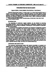
Design and Simulation of a PCI Express based Embedded System Faraj Nassar1, Jan Haase1, Christoph Grimm1, Herbert Nachtnebel1, Majid Ghameshlu2 1 Institute of Computer Technology, Vienna University of Technology 2 Siemens IT Solution and Services PSE, Siemens AG Austria {nassar, haase, grimm, nachtnebel}@ict.tuwien.ac.at,
[email protected] Abstract In this paper, a brief introduction to the theory of PCI Express (PCIe) bus system is given. In addition to that, the capabilities of this bus system are demonstrated by designing and simulating a PCIe based embedded data communication system. This system utilizes the Xilinx Microblaze soft processor core, the Xilinx PCIe core, and the Philips PX1011A physical layer. A basic, efficient, and simplified On-chip Peripheral Bus (OPB) to PCIe Bridge is developed here from scratch to bridge the Microblaze and the PCIe protocol layers. Data communication between the designed PCIe-based intelligent Endpoint device, in the PCIe topology, and the system memory, as well as the Central Processing Unit (CPU), through the Root Complex, is simulated. Keywords: IP, Microblaze, PCI, PCIe Core, PCIe Endpoint, On Chip Peripheral Bus (OPB), OPB IPIF, OPB to PCIe Bridge, Philips PX1011A PHY.
1 Introduction The platform of Today's PCs consists of many local buses with different requirements, to allow the communication of different devices with each other. Nowadays, many of these modern electronic devices are demanding a high bandwidth, even higher than what already existing input and output (IO) bus systems can deliver. An example of these is the Peripheral Component Interconnect (PCI). These bus systems are reaching their practical limits and are facing serious problems and shortcomings that prevent them from being able to provide the bandwidth and features needed by the electronic industry, which keeps needing to an increased bandwidth as well as a simple electrical connectivity. All these factors together have motivated the engineering of a new IO bus system, the so-called Peripheral Component Interconnect Express (PCIe), which has been adopted as a general purpose IO device interconnect in different applications, such as desktop, server, mobile, workstations, computing, and communication platforms. The first IO buses generation was introduced in the 1980s, including the Industry Standard Architecture (ISA), which enables a bandwidth of 16.7 Mbytes/s, a sufficient one at that time. Extended ISA (EISA) and Video Electronics Standards Association (VESA) are other buses of this generation.
ISBN 978-3-200-01330-8
In the 1990s, the second IO buses generation was started with different approaches. In 1993 the PCI 33 MHz bus was released. At that time, a 32-bit version of this bus was enough to deliver a bandwidth of 133 Mbytes/s, which met the bandwidth requirements of the available IO peripherals. A 64-bit version of this PCI bus delivers a bandwidth of 266 Mbytes/s [1]. However, due to the increase in the processor speeds and the bandwidth needs of newer IO technologies, the PCI bus frequency was increased in 1995 from 33 to 66 MHz, to increase the bandwidth from 133 Mbytes/s to 266 Mbytes/s for a 32-bit PCI, and from 266 Mbytes/s to 533 Mbytes/s for a 64-bit PCI, correspondingly [2]. Several practical limitations of the PCI 66 MHz bus and the emerging of new high end system technologies that continued asking for higher bandwidths led in 1999 to the release of a new derivation of the PCI called the PCI-X bus. The PCI-X bus has frequencies of 66 and 133 MHz and enables a bandwidth up to 1.066 Gbytes/s. These frequencies were increased to 266 and 533 MHz in the first quarter of 2002, to increase the bandwidth provided up to 4 Gbytes/s [2]. Another bus system in the second generation is the Accelerated Graphics Port (AGP). However, in order to meet the higher bandwidth requirements and to satisfy the bandwidth hungry devices, a new bus system was still needed. The third and latest generation IO bus system is the PCIe, which was released in the second quarter of 2002. It evolved from the PCI and overcame the limitations of the PCI. The PCIe began shipping in standard desktop PCs in 2004. A x1 PCIe bus provides theoretically a bandwidth of 500 Mbytes/s, a x16 PCIe can provide up to 8 Gbytes/s, and a x32 provides 16 Gbytes/s [2]. In this paper, the capabilities of this PCIe bus system are demonstrated by designing and simulating a PCIe based embedded system for customer reference. In this system an intelligent Endpoint device, employing this technology, is able to write a double word (DW) having 32 bits to a location within the system memory and read this data back. This system also enables data communication between the CPU through the Root Complex and this Endpoint device.
2 PCI Express 2.1 PCI Express Introduction Unlike the parallel PCI bus, the PCIe bus is serial. The PCIe link implements a high performance, high speed,
- 73 -
Institut für Integrierte Schaltungen
Austrochip 2008
Johannes Kepler Universität Linz
point-to-point, dual simplex, low-pin-count and differential signalling link for interconnecting devices. The PCIe link, shown in Figure 1, implements the physical connection between two devices in the PCIe topology. A PCIe interconnect is constructed of either a x1, x2, x4, x8, x12, x16, or x32 point-to-point link. A x1 link has 1 lane or 1 differential signal pairs in each direction, transmitter and receiver, with a total of 4 signals. Correspondingly, x32 link has 32 lanes or 32 signal pairs for each direction, with a total of 128 signals [2].
completion TLP back to the requester, unlike the memory read TLP, where the completer is supposed to return a completion TLP back to the requester. The completer returns either a CPLD, if it is able to provide the requested data, or a Completion without data (CPL), if it fails to obtain the requested data.
CPU Memory FSB
Graphics
PCIe employs a packet-based communication protocol with a split transaction. Communication in this bus system includes the transmission and reception of packets called Transaction Layer packets (TLPs). The transactions supported by the PCIe protocol can be grouped into four categories: Memory, IO, Configuration, and Message transactions [2].
PCIe
Root Complex x1 PCIe link EP: Endpoint FSB: Front Side Bus
Switch PCIe
2.2 PCI Express Topology The PCIe topology shown in Figure 1 contains different components. A Root Complex, PCIe switches, PCIe Endpoints, and optional PCIe to PCI bridges.
The PCIe Endpoint (EP) is a device which can be a requester that originates a PCIe transaction or a completer that responds to a PCIe transaction addressed to it. PCIe Endpoints are peripheral devices such as Ethernet, USB or graphic devices. In order to connect some PCI devices to the PCIe fabric, a PCIe to PCI Bridge must be used.
2.3 PCI Express Architecture PCIe has a layered architecture as depicted in Figure 2. It consists of the Transaction Layer, the Data Link Layer and the Physical Layer. On the top of these three layers resides the Software Layer, or device core. Each of these layers is further divided into two sections: transmitter and receiver. The transmitter is responsible for processing the Transaction Layer Packets requested from the device core before being transmitted across the PCIe link. The receiver processes the incoming TLPs before sending them to the device core. To demonstrate the functionality of the PCI Express protocol and for the purpose of this paper, 32-bit addressable memory write/read and Completion with Data (CPLD) TLPs will be considered. The memory write TLP is considered to be a posted transaction where the requester transmits a request TLP to the completer. This in turn does not return a
PCIe
PCIe-PCI Bridge
Switch PCIe
The Root Complex connects the CPU and the memory to the PCIe fabric. The main purpose of the Root Complex is to generate transaction and configuration requests by request of the CPU. PCIe implements a switch-based topology in order to interconnect multiple devices as shown in Figure 1.
ISBN 978-3-200-01330-8
Memory bus
x2 EP
PCIe
PCI
x1 EP
PCI-Slots
Figure 1. PCI Express Topology
Figure 2 also shows the assembly and disassembly of a PCIe TLP. It also illustrates the contribution of each layer to this TLP. The device core sends to the Transaction Layer the information required to assemble the TLP. This information contains the Header (HDR) and the Data Payload, if exists. The main functionality of the Transaction Layer is the generation of TLPs to be transmitted across the PCIe link and the reception of TLPs received from the PCIe link. This layer appends a 32-bit End to End Cyclic Redundancy Check (ECRC) to the TLP to be transmitted. These 32 bits are stripped out by the same layer at the receiver side. The Data Link Layer (DLL) is responsible for ensuring a reliable data transport on the PCIe link. The received TLP from the transaction layer is concatenated with a 12-bit sequence ID and a 32-bit Link CRC (LCRC) as shown in Figure 2 [4]. These added bits are stripped out from the incoming TLP by the same layer in the receiving device before being transferred to the Transaction Layer. The physical layer of a PCIe device is responsible for driving and receiving the Low Voltage Differential Signals (LVDS) at a high speed rate of 2.5 Gbps each way. It interfaces the device to the PCIe fabric. Such an interface is scalable to deliver a higher bandwidth.
- 74 -
Institut für Integrierte Schaltungen
Austrochip 2008
Johannes Kepler Universität Linz
HDR
Data
Device A
Device Device BB
Device Core
Device Core
Transaction
Transaction
Layer
Layer
Data Link Layer
Data Link Layer
HDR
Data
1DW HDR
Data ECRC
SEQ. # HDR Data ECRCLCRC
HDR
Data ECRC
12-bit
1DW
SEQ. # HDR Data ECRCLCRC 1B
Start SEQ. # HDR Data ECRCLCRC END
Physical Layer
TX
RX
Physical Layer
TX
Start SEQ. # HDR Data ECRCLCRC END
RX
Figure 2. PCI Express Architecture and Transaction Layer Packet (TLP) Assembly/Disassembly
The TLPs are transferred to this layer for the purpose of transmission across the link. This layer also receives the incoming TLPs from the link and sends them to the Data Link Layer. This layer appends 8-bit Start and End framing characters to the packet before being transmitted. The physical layer of the receiving device in-turn strips out these characters after recognizing the starting and ending of the received packet, and then forwards it to the Data Link Layer. In addition to that, the physical layer of the transmitter issues Physical Layer Packets (PLPs) which are terminated at the physical layer of the receiver, such PLPs are used during the Link Training and Initialization process. In this process the link is automatically configured and initialized for normal operation; no software is involved. During this process the following features are defined: link width, data rate of the link, polarity inversion, lane reversal, bit/symbol lock per lane, and lane-to-lane deskew (in case of multilane link) [2].
3 PCI Express Endpoint Design 3.1 Design Overview In this paper, the x1 PCIe Endpoint is considered. In Figure 1, the Endpoint is an intelligent device which acts as a target for downstream TLPs from the CPU through the Root Complex and as an initiator of upstream TLPs to the CPU. This Endpoint generates or responds to Memory Write/Read transactions. When the Endpoint acts as a receiver, the CPU issues a store register command to a memory mapped location in the Endpoint. This is done by having the Root Complex generate a Memory Write TLP with the required memory mapped address in the Endpoint, the payload size (a DW in this design), byte enables and other Header contents. This TLP moves downstream through the PCIe fabric to the Endpoint. Routing of the TLP in this case is based on the address within its Header.
ISBN 978-3-200-01330-8
A termination of the transaction takes place when the Endpoint receives the TLP and writes the data to the targeted local register. To read this data back, the CPU issues a load register command from the same memory mapped location in the Endpoint. This is done by having the Root Complex generate a Memory Read TLP with the same memory mapped address and other Header contents. This TLP moves downstream through the PCIe fabric to the Endpoint. Again, routing here is based on the same address within the Header. Once the Endpoint receives this Memory Read TLP, it generates a Completion with Data TLP (CPLD). The Header of this CPLD TLP includes the ID number of the Root Complex, which is used to route this TLP upstream through the fabric to the Root Complex, which in-turn updates the targeted CPU register and terminates the transaction. The other way around, is to have the Endpoint act as a bus master and initiate a Memory Write TLP to write 1 DW to a location within the system memory. This TLP is routed upstream toward the Root Complex which in turn writes the data to the targeted location in the system memory. If the Endpoint wants to read the data it has written, it generates a Memory Read TLP with the same address. This is steered to the Root Complex, which in-turn accesses the system memory, gets the required data and generates a Completion with this data TLP. This CPLD TLP is routed downstream to the Endpoint through the PCIe fabric. The Endpoint receives this TLP, updates its local register and terminates the transaction. Figure 3 shows the layered structure of the PCIe Endpoint device. There are two different solutions for the physical layer (PHY). In the first solution, this layer can be integrated with the other layers in the same chip. Doing so increases the complexity of this chip and provides a higher integration level. This integrated solution has one key advantage when designing using an FPGA. It uses a smaller number of IO pins, which enables easier timing closure. An example of this integrated solution is offered by Xilinx in their newly introduced Xilinx Virtex-5 PCIe Endpoint block [5].
- 75 -
Institut für Integrierte Schaltungen
Austrochip 2008
Johannes Kepler Universität Linz
Microblaze also controls the transmitting and receiving of TLPs. Endpoint Device
3.3 Complete Design
Device Core RX
TX
Transaction Layer Data Link Layer
Application Layer Microblaze based system
Protocol Layers XILINX PCIe PIPE Endpoint 1-lane Core
Figure 4 shows the complete designed PCIe Endpoint. This system embeds the Xilinx Microblaze, which implements a 32-bit Reduced Instruction Set Computer (RISC) and operates at a frequency of 50MHz. Having the Microblaze as a soft core processor enables the design of a unique and customized PCIe peripheral device to be connected as a slave to it [8]. 50 MHz 32 Bits
DLMB
ILMB Controller
DLMB Controller
PCI Express Fabric
50 MHz 32 Bits
OPB_PCIe_Bridge
62.5 MHz 32 Bits
Figure 3. Endpoint Design
Unlike the first solution which is quite expensive, the second solution offers a low cost way of implementing the PCIe Endpoint. In this solution, the physical layer exists in one chip, and the other layers are designed in another chip. In this two-chip solution, a smaller FPGA with external PHY can be used. This PHY supports x1 PCIe designs. Having the practical bandwidth provided by x1 PCIe is 2.0 Gbps requires an internal interface of 8 bits running at 250 MHz or an interface of 16 bits running at 125 MHz. This solution has the disadvantage of higher number of IO pins.
Instruction BRAM
3.2 Protocol and Application Layers The protocol layers containing the logical sub-layer of the physical layer, the data link layer and the transaction layer are implemented using the Xilinx PCI Express Physical Interface for PCI Express (PIPE) Endpoint 1Lane IP core [7]. A Microblaze based system was built up to implement the Application layer of the designed PCIe Endpoint. In this system, the PCIe core is attached as a slave to the processor, which in-turn tries to access the configuration space of this core, reading from and writing to this space. In the application layer, the Microblaze is responsible for sending the required Header and data payload to the transaction layer. When a TLP is received by the PCIe Endpoint, the Header and the payload, if exists, will be forwarded to the Microblaze for further processing. The
Data BRAM
XILINX PCIe PIPE 1-Lane Core
BRAM
Xilinx® Spartan-3 FPGA
Spartan-3 PCI Express Starter Kit
PXPIPE
250 MHz 8 Bits
PHILIPS PHY
PCI Express Link
2.5 GHz Serial
Figure 4. Complete PCIe Endpoint Device. BRAM: Block Random Access Memory, LMB: Local Memory Bus, DLMB: Data LMB, ILMB: Instruction LMB, IPIF: Intellectual Property Interface, FPGA: Field Programmable Gate Array, PIPE: Physical Interface for PCI Express, PXPIPE: Philips PHY Specification PIPE
In this paper, the Xilinx Spartan-3 FPGA and Philips PX1011A two-chip solution was used for designing the PCIe Endpoint [6]. This solution was chosen due to a management issue at the department where this work was conducted.
ISBN 978-3-200-01330-8
USER LOGIC
ILMB
MicroBlaze
OPB IPIF
Physical Layer PHILIPS PHY
On-Chip Peripheral Bus (OPB)
Physical Layer
The Microblaze has different bus interfaces, connecting it with different peripherals. For example, the Local Memory Bus (LMB) allows the communication between the processor and the Block Random Access Memory (BRAM), which is loaded with the application program to be executed by the Microblaze. This program is written in C, using special library provided by Xilinx. It is compiled into an executable link format (ELF). The Microblaze has a Harvard structure, in which the BRAM consists of two sections, data and instructions. These sections are accessed by the processor through memory controllers over the local memory bus. The Xilinx On-Chip Peripheral Bus (OPB), which implements the IBM CoreConnect On-Chip Peripheral Bus, has two 32-bit separate paths for data and address [8]. This bus is used to connect peripherals to the Microblaze, which masters the bus.
- 76 -
Institut für Integrierte Schaltungen
Austrochip 2008
Johannes Kepler Universität Linz
The PCIe core can not be directly connected to the OPB as a slave, because of the incompatibility of its interfaces with the OPB protocol. To solve this compatibility issue, a bridge was developed to bridge the OPB and the PCIe core. This bridge interfaces the OPB with its standard protocol through the OPB Intellectual Property Interface (OPB IPIF) from one side, and the PCIe core through the USER LOGIC model from the other side. The internal structure of this USER LOGIC model is shown in Figure 5. This model implements the logic needed to transmit/receive TLPs across the PCIe link and to access the configuration space of the PCIe core. The PCIe core transaction interfaces are synchronized with a clock of 62.5 MHz generated from the core as indicated in Figure 5.
x1 PCIe design), the PCIe downstream port model, the Philips PHY and the Design Under Test (DUT) are instantiated. Application Program .elf
Design Under Test (DUT)
Output logs .txt
PXPIPE Interface
Philips PHY PX1011A
PCIe
Link
PCIe Downstream Port Model
Test Program .v
Transmit Transaction
Interface
PCIe Receiving State Machine
Interface
Register Read
Receive Transaction
PCIe Transmission State Machine
Software accessible Register Bank IP Interconnect (IPIC)
Boardx01 Figure 6. PCIe Testbench Top-level
Register Write PCIe Configuration space Access READ/WRITE State Machine
Configuration Interface
IP Interconnect (IPIC)
USER LOGIC
Figure 5. USER LOGIC Internal Structure
The PCIe core interfaces with the Philips PHY using the Philips PHY Specification Physical Interface for PCI Express (PXPIPE), defined by Philips Semiconductors, which implements an extended version of the Physical Interface for PCI Express (PIPE), defined by Intel. PXPIPE is a 250 MHz source synchronous interface, which provides two clocks, one for transmission, and the other for reception. Depicted in the Figure are the interfaces of Philips PHY to the PCIe link, which are the low voltage differential signals (LVDS) driven at a high data rate of 2.5 Gbps.
4 PCI Express based System Simulation The designed PCIe Endpoint was integrated in a top level Testbench to simulate its functionality. Figure 6 shows the top level of this Testbench (which is written in Verilog HDL). The Figure depicts the hierarchy of this Testbench. In the top level named boardx01 (indicates a
ISBN 978-3-200-01330-8
The PX1011A behavioural model is a packaged model, which can be simulated in ModelSim or other standard Hardware Description Language (HDL) simulators. The IP Model Packager from Cadence was used to generate this model. This model can be integrated in any simulator that supports either the IEEE standard 1499 – the open Model Interface, or the IEEE standard 1364 – the Verilog PLI 1.0 (Programming Language Interface). This model was provided by NXP Semiconductors. In a PCIe Testbench, a simulation model is needed to implement the functionality of the Root Complex and the PCIe switch in the PCIe topology shown in Figure 1. The Xilinx PCIe downstream port simulation model [9], offered by Xilinx when generating the core, which is written in Verilog HDL was used for the purpose of simulation in the PCIe based system. The main functionality of this model is to generate downstream TLPs from the CPU to the PCIe Endpoint and to receive upstream TLPs from the PCIe Endpoint to the CPU. In addition to the main functionality, this model does the initialization of the PCIe core's configuration registers, verifies the transmission and reception of TLPs by generating TLP logs, and provides a kind of Test Programming Interface (TPI). For the purpose of functional simulation, the model implements an output logging mechanism. Three different text files are generated, when running a defined task. One of the files summarizes the received TLPs, another shows the transmitted TLPs, and the third file includes error messages, in case any errors are detected. Several test cases were conducted to simulate the functionality of this designed Endpoint device. Figure 7 shows the simulation results of the case, when the Endpoint responds with a CPLD TLP to a memory read TLP issued by the CPU, refer to the design overview in Section 3 of this paper for more details. This diagram shows the PCIe transmission state machine. In this state machine and for the case of transmitting a CPLD TLP, the following sequence of events has to be performed on
- 77 -
Institut für Integrierte Schaltungen
Austrochip 2008
Johannes Kepler Universität Linz
the PCIe Transmit Transaction interfaces as shown in Figure 7: First, after receiving an active high control signal (compl_gen) from the processor requesting the generation of a CPLD, the machine activates, at the next positive edge of the transaction clock (trn_clk), the active low start of frame signal (trn_tsof_n) and the active low transmit source ready signal (trn_tsrc_rdy_n) to indicate the availability of valid data from the user logic application, and then presents the first TLP’s DW on the 32-bit transaction data signal (trn_td). Note that, in case of transmitting, the Endpoint is enabled as a master through the signal master_enable. Second, at the next clock cycle, the state machine deactivates trn_tsof_n and presents the rest of the TLP’s DWs on trn_td. The PCIe core keeps the activation of trn_tdst_rdy_n. Third, this state machine activates trn_tsrc_rdy_n and the active low end of frame signal (trn_teof_n) together with the last DW of data. It also activates the signal cpld_transmitted to indicate that a CPLD TLP is transmitted. Finally, at the next clock cycle, the state machine deactivates trn_tsrc_rdy_n to indicate the end of valid transfer of data on trn_td.
5 Conclusion Within this paper, the various capabilities of the PCIe bus protocol were demonstrated. In a platform based on PCIe topology, an Endpoint device was designed. This Endpoint embeds the Microblaze soft core of Xilinx, which is bridged to the PCIe protocol layers implemented by the PCIe core, to serve the data communication between this intelligent Endpoint and the CPU/system memory through the Root Complex. A basic and simplified OPB to PCIe Bridge was developed to bridge the Microblaze and the PCIe protocol layers. The PCIe core was generated, configured and customized using the Xilinx CORE generator. A packaged simulation model, provided by NXP Semiconductors, was used to simulate the functionality of the PCIe physical layer. This model interfaces the simulation tool using the Verilog HDL Programming Language Interface (PLI). In a modified version of a PCIe Testbench (provided by Xilinx) and with the help of the simulation tool ModelSim, the functionality of the designed Endpoint was simulated and verified.
In addition to that, the designed Endpoint was system was prepared to be implemented in the Xilinx Spartan-3 FPGA, located on the Xilinx PCIe Spartan-3 Starter Kit. It can also be concluded that working with PCIe requires the knowledge of the PCIe protocol, because most of the available PCIe IP cores don’t provide compatible interfaces, which would allow them to be directly connected to the regarded processor. Therefore, in most cases, an effort must be made to develop a bridge that allows an easy connection of the PCIe peripheral to the processor. Furthermore, the functionality of this designed Endpoint can be more complicated than this simple data transfer task. One can further extend the capabilities of this Endpoint by reconfiguring the PCIe core to include IO mapped space.
Acknowledgment The results in this paper are from the work which was conducted as a Master thesis in the field of Microelectronics, in cooperation with the Institute of Computer Technology at the Technical University of Vienna and the CES Design Services business unit of Siemens IT Solutions and Services PSE, Austria. I’m very grateful for those who supported and helped me during conducting this work.
References [1] Don Anderson and Tom Shanley, “PCI Architecture”, MINDSHARE INC., 1999.
System
[2] Don Anderson, Ravi Budruk, and Tom Shanley, “PCI Express System Architecture, MINDSHARE INC., 2004. [3] Ajay V. Bhatt “Creating a PCI Express™ Interconnect”, Technology and Research Labs, Intel Corporation, 2002. [4] “PCI Express™ Base Specification”, Revision 1.1, March 28, 2005 [5] “Virtex-5 Integrated Endpoint Block for PCI Express Designs”, User Guide, UG197 (v1.1), March 20, 2007. [6] Koninklijke Philips Electronics N.V, “NXP x1 PHY single-lane transceiver PX1011A (I)”, September 2006. [7] “LogiCORE™ PCI Express PIPE Endpoint 1-Lane v1.5”, User Guide, UG167, September 21, 2006. [8] “MicroBlaze Processor Reference Guide”, UG081 (v6.3), User Guide, August 29, 2006. [9] Xilinx User Guide “LogiCORE™ PCI Express® Endpoint Block Plus v1.2”, UG341 February15, 2007.
Figure 7. PCIe Endpoint’s Completion with Data (CPLD) Transaction Layer Packet (TLP)
ISBN 978-3-200-01330-8
- 78 -
Institut für Integrierte Schaltungen


![[PDF]Download PCI Express System Architecture ... - Google Sites](https://m.moam.info/img/260x300/pdfdownload-pci-express-system-architecture-google_6477dc65097c474c228c7ef7.jpg)


