Finally, protocol verification using an exhaustive verification tool known as Mur' is discussed. Key Words and Phrases: Update-based cache coherence protocols ...
DESIGN AND VALIDATION OF UPDATE-BASED CACHE COHERENCE PROTOCOLS
David B. Glasco Bruce A. Delagi Michael J. Flynn
Technical Report No. CSL-TR-94-613
March 1994
This work was supported by NASA under contract NAG2-248 using facilities provided by Sun Microsystems, Inc.
DESIGN AND VALIDATION OF UPDATE-BASED CACHE COHERENCE PROTOCOLS by David B. Glasco Bruce A. Delagi Michael J. Flynn Technical Report No. CSL-TR-94-613 March 1994
Computer Systems Laboratory Departments of Electrical Engineering and Computer Science Stanford University Stanford, California 94305
Abstract In this paper, we present the details of the two update-based cache coherence protocols for scalable shared-memory multiprocessors that were studied in our previous work. First, the directory structures required for the protocols are briefly reviewed. Next, the state diagrams and some examples of the two update-based protocols are presented; one of the protocols is based on a centralized directory, and the other is based on a singly-linked distributed directory. Protocol deadlock and the additional requirements placed the protocols to avoid such deadlock are also examined. Finally, protocol verification using an exhaustive verification tool known as Mur' is discussed.
Key Words and Phrases: Update-based cache coherence protocols, hardware-based cache coherence protocols, shared-memory multiprocessors
c 1994 Copyright by David B. Glasco Bruce A. Delagi Michael J. Flynn
iii
Contents 1
Introduction
1
2
Directory Structures
1
2.1 2.2 2.3
::::::::::::::::::::::::::::::: Distributed Directory : : : : : : : : : : : : : : : : : : : : : : : : : : : : : : : Scalability of Directory Structures : : : : : : : : : : : : : : : : : : : : : : : : :
Centralized Directory
1 2 3
3
Protocol Deadlock
4
4
Update-Based Protocol
6
4.1
Centralized Directory (CD-UP)
4.2
Distributed Directory (DD-UP)
:::::::::::::::::::::::::: ::::::::::::::::::::::::::
6 17
5
Protocol Verification
29
6
Summary
30
1
1
Introduction
In our previous work [8, 7, 9], we demonstrated the possible performance gains from update-based cache coherence protocols when compared to invalidate-based protocols for a set of fine-grain scientific applications running on a scalable shared-memory multiprocessor. In this paper, we present the details of the update-based cache coherence protocols and discuss verification of the protocols. The paper is organized as follows. Section 2 gives a brief review of the directory structures required for the protocols, and section 3 discusses protocol level deadlock. Next, section 4 presents the details of the update-based protocols. In particular, section 4.1 describes a centralized directory protocol, and section 4.2 describes a singly-linked distributed directory protocol. Section 5 discusses verification of the protocols using an exhaustive verification tool called Mur' [5]. And finally, section 6 summarizes the paper.
2
Directory Structures
Directory-based cache coherence protocols must maintain a directory entry for each memory line in the system. This directory entry indicates which caches in the system have a copy of the respective memory line. Each directory entry can be stored in a single, central location (centralized directory protocol) or distributed among the caches holding a copy of the line (distributed directory protocol). In both cases, the directory entries are distributed throughout the system with their respective memory lines.
2.1 Centralized Directory In a centralized directory (CD) protocol, each directory entry contains a pointer to each cache in the system that contains a copy of the respective memory line. In the CD protocols studied in this work, a fully mapped directory is used in which there is a single bit pointer for each cache in the system [18]. For example, figure 1 shows a directory entry for a memory line in a four cache system. In the example, caches 1 and 3 have a copy of the given memory line. In this fully mapped scheme, each directory entry contains NCaches bits for a total of
Bits
= =
NCaches � NMemoryLines O(NCaches NMemoryLines )
bits where NCaches is the number of caches and NMemoryLines is the number of memory lines in the system.
2
Directory
1 0 1 0
Cache 1
Cache 2
Cache 3
One bit vector per memory line. Bits = N Caches
Cache 4
Figure 1: Centralized Directory Structure
2.2 Distributed Directory In a distributed directory (DD) protocol, a linked list structure is used to maintain the list of caches that have a copy of a given memory line. The directory entry contains a pointer to the head of this list, and each cache line contains the necessary pointers to construct the list. The list may be singly-linked or doubly-linked. It is important to note that the order of the list is not optimized in any way. The order is determined by the order that the requests for the memory line reach the directory. 2.2.1
Singly-Linked Directory Structures
In a singly-linked distributed directory protocol [20], a singly-linked list is used to maintain the list as shown in figure 2. In this example, caches 0, 2 and 3 have a copy of the line. Directory
One cache pointer per memory and cache line. Bits per Pointer = log N
3
2
Cache 3
Cache 0
0
2
Cache 2
Caches
Cache 1
Figure 2: Singly-Linked Distributed Directory Structure In this case, each directory entry contains log2 (NCaches ) bits, and each cache line must also include a single pointer. This requires a total of
Bits
= =
NMemoryLines log2 (NCaches ) + NCacheLines log2 (NCaches ) log2 (NCaches )(NMemoryLines + NCacheLines )
3 =
O(log2 (NCaches )NMemoryLines )
bits, which scales better than the fully-mapped CD directory structure as the size of the system increases. 2.2.2
Doubly-Linked Directory Structures
Alternatively, a doubly-linked directory structure may be used [11], as shown in figure 3. In this example, caches 0, 2 and 3 have a copy of the line. Directory
One pointer per memory line and two per cache line. Bits per Pointer = log N
3
2
Cache 3
Cache 0
M 0
3 2
Cache 2
Caches
Cache 1
0
Figure 3: Doubly-Linked Distributed Directory Structure The amount of storage required is slightly more than that of the singly-linked distributed directory structure since each cache line must now maintain two pointers. This requires
Bits
= = =
NMemoryLines log2 (NCaches ) + 2NCacheLines log2 (NCaches ) log2 (NCaches )(NMemoryLines + 2NCacheLines ) O(Log2 (NCaches )NMemoryLines )
bits of storage.
2.3 Scalability of Directory Structures As shown above, the centralized directory structure scales as O(NCaches NMemoryLines ), but the distributed directories scale better as O(log2 (NCaches )NMemoryLines ). However, several different approaches have been suggested to improve the scalability of the centralized directory schemes. These include limited pointer schemes and cached directories. The limited pointer schemes limit the number of cached copies of each memory line. When this limit is exceeded, the limited pointer schemes either invalidates one of the copies to make room for the new request [1], assumes all caches now have a copy of the line [1], switches to a coarse grain mode where each bit represents several caches [10] or traps to software to extend the directory list [3]. With a limited pointer scheme, the centralized directory scales as O(NLimited NMemoryLines ) where NLimited is the number of bits in the limited directory entry.
4 The other approach is to note that the maximum number of cached copies of a memory line is limited by the total size of all caches and not the size of memory. In this case, a directory cache could be used to cache this smaller set of directory entries [10]. Also, the bits for each directory entry can be dynamically allocated out of a pool of directory bits [17]. Several studies have indicated that the average number of shared copies of a memory line is small [2, 16, 21, 1, 6]. Therefore, the limited directory schemes result in minimal performance loss [1, 3, 10]. Similarly, the cached directory has also been shown to have a minimal affect on execution time [10]. Some of the limited pointer schemes require that the directory be able to invalidate cached copies of a line. The centralized directory update-based protocol presented in this work currently does not support invalidations, but the protocol could be extended to support such directory initiated invalidations.
3
Protocol Deadlock
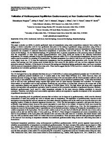
If the system has finite buffering, then protocol level deadlock is possible [19, 15, 8]1. For example, figure 4 shows two caches that are sending requests to each other through a set of finite buffers. Each buffer can hold a single request. First, cache A sends two requests to cache B, and it begins processing a request that will generate another request to cache B. But because the buffers are already full, cache A must wait until a buffer becomes available before it is able to complete the processing of the new request. Meanwhile, cache B generates two requests to cache A, and it attempts to generate a third request. The system is now deadlocked. Neither cache A nor B can complete the processing of their current request because their output buffers are full, and they will never empty. A timeout is used to detect such deadlocked situations. There are two techniques to handle protocol level deadlock. The first technique attempts to avoid deadlock by using local memory to expand the buffer space as needed [14]. When a buffer fills and a possible deadlock situation is detected, packets are removed from the buffer and placed in a secondary buffer created in the local memory. The cache and directory controllers must then process packets from this secondary buffer until it is empty. This technique essentially creates an almost infinitely sized buffer, but it requires a tight coupling of the cache controller, directory controller and local memory. The second technique attempts to break the deadlock by removing requests from the deadlocked buffer and sending them back to their source through an exception network [15, 19, 8]. To minimize the probability of deadlock, messages are statically divided by the protocol into request and reply messages. A request message is a message that may generate another message and, therefore, lead to deadlock. A reply message is a message that never generates any new messages and, therefore, can always be consumed. This is the technique assumed throughout this work. This second technique requires three logical networks: a request, reply and exception network. The reply network is deadlock free since replies can always be consumed. The request network 1
The actual network is assumed to be deadlock free.
5 Single request buffers A2
A1
Cache A
Cache B (Busy)
(a) Cache A sends two requests to Cache B which is currently busy. Cache A begins processing a request that will generate another request for Cache B.
Cache A (Busy)
A2
A1
B1
B2
Cache B (Busy)
(a) Cache A can not complete current request since the buffer is full. Meanwhile, Cache B generates two requests to Cache A and attempts to generate a third request. Neither cache can proceed since their output buffers are full. The system is deadlocked.
Figure 4: Protocol Level Deadlock may experience deadlock if the request at the head of the buffer generates another request. If the request generates a reply, then the request can always be completed since the reply network will never deadlock. The request-request deadlock is broken by sending the request at the head of the deadlocked buffer back to the source of the request to be retried. The act of removing a message from the deadlocked network may break the deadlock. If not, this process would remove another request packet and send it back to the source. This is repeated until the deadlock condition is eliminated. The frequency of deadlock is dependent on the size of the buffers. If reasonable buffer sizes are used, deadlock is extremely rare [19, 15]. In the system simulated in this work, the cache and memory buffers were 128 words deep, and deadlock never occurred for any of the cases examined [8, 7, 9]. The separate request and reply networks also require logically separate controllers in both the cache and directory. Otherwise, a cache that is attempting to process a request would not be able to consume pending replies. This would violate the condition that replies always be consumed. Also, since replies are always consumed, the reply network may also be used as the exception network.
6
4
Update-Based Protocol
This section presents the details of the update-based protocols. Since the scalability of the directory structures is still an open research topic, update-based protocols are presented for both a fullymapped centralized directory and a singly-linked distributed directory. Both update-based protocols require an order preserving network. An order preserving network guarantees that messages between nodes are received in the same order that they are sent. In the protocols examined in this work, each memory line may be in one of several states. These states usually specify if there is a single or multiple cached copies of the memory line and if memory’s copy of the line is valid. Each cache line may also be in one of several states. These states specify the local processor’s access privileges for the cached copy of the line. The state may also specify if the cache has the only cached copy of the memory line. In this section, the actions of the cache coherence protocols will be described using state transition diagrams for both the memory and cache line states. The state of the lines may change as a result of a request from the local processor, the directory or a remote cache.
4.1 Centralized Directory (CD-UP) In this section, the details of the centralized directory update-based protocol (CD-UP) are presented. 4.1.1
Cache and Memory Line States
In the CD-UP protocol, a cache line can be in one of five states:
� Invalid - the cache’s copy of the line is not valid � Pending - the cache has issued a miss and is waiting for a reply � Shared - the line is shared by multiple caches - writes must update other cached copies of the line and memory � Replacing - the cache’s copy is being replaced � Exclusive - the cache’s copy is the only copy of the memory line (cache is “owner” of line), and a memory line can be in one of four states:
� Absent - no cached copies of the line exist � Shared - at least one cache has a copy of the line - memory is consistent � Exclusive - one cache has a copy of the line - memory is not consistent � Pending - the directory is awaiting a write back for the memory line.
7 Table 1 gives a description of the protocol messages. The first column of the table gives the message name, and the next two columns give the source and destination type of the message. The source (Src) and destination (Dst) can be a processor (P), a cache (C) or a directory (D). The next column specifies if the message is a request (Req) or reply (Rep). This determines which network channel the message will traverse. The next column gives a brief description of the message, and the data column specifies what data type, a word or line, is sent with the message. Finally, the last column specifies what actions are taken by the destination node. These actions may include incrementing and decrementing the pending write counter (PWC) and the pending update counter (PUC). These counters are used to determined when all issued writes have been performed. Other actions include writing the data value (V) from the message into the cache line data (CD) or memory line data (MD) at the specified cache line offsets (O) and setting or clearing the directory (DIR) pointers. A Stall indicates that the processor is stalled until the proper reply is received by the cache, and Block indicates that the write is not processed, and it is not retired from the write buffer. A pending bit (PB) is used to control the writing of data into the cache line for certain conditions. The pending bits are identical to the valid bits in the invalidate-based protocols [19]. Figure 5 shows the state transition diagrams for cache and memory lines. The diagrams show the state changes for each received message and the resulting messages generated, if any.
8
Message
Src
Dst
RD WR
P P
C C
Type
Processor read Processor write
Description
Data
R FENCE
P P
C
Line replacement Stall until writes performed
RM WM WW RL RLD
C C C C C
D D D D D
Req Req Req Req Req
Read miss Write miss Write word to directory Replace line Replace line with data
SR
M or C
C
Req
Shared miss reply with update count (U)
Line
ER
D
C
Rep
Exclusive miss reply
Line
WB WBU
D D
C C
Req Req
UW
D
C
Req
Write back line to directory Write back line to directory with data update Update word to cache(s)
RA WA
D D
C C
Req Req
UA
C
C
Rep
Replacement ack Write ack with update count (U) Update ack
LR LRD UL
C C C
D D D
Rep Rep Rep
Line already replaced Line already replaced Write back of line
RMB WMB WWB LRB LRDB UWB WBB WBUB
D D D D D C C C
C C C C C D D D
Req Req Req Req Req Req Req Req
Bounce RM to cache Bounce WM to cache Bounce WW to cache Bounce LR to cache Bounce LR to cache Bounce UW to directory Bounce WB to directory Bounce WBU to directory
Word
Word Word Line
Destination Actions If Pending & PB(O) = F Then Stall If Shared & PB(O) = T Then Stall Else CD(O) = V If Invalid Then PWC += 1 If Pending Then PB(O) = T If Shared Then PWC += 1, PB(O) = T If ForAny O: PB(O) = T Then Stall Stall until PWC = PUC = O DIR(Src) = T MD(O) = V, DIR(Src) = T MD(O) = V DIR(Src) = F MD = V, DIR(Src) = F PWC -= 1, PUC += U Forall O: If PB(O) = F Then CD(O) = V Else PB(O) = F, send WW with CD(O) PWC -= 1 Forall O: If PB(O) = F Then D(O) = V Else PB(O) = F CD(O) = V
Word
If PB(O) = F Then CD(O) = V PWC -= 1, PUC += U, PB(O) = F PUC -= 1
Word Line
Word
MD = V Resend RM Resend WM, V = CD(O) Resend WW, V = CD(O) Resend LR Resend LRD Resend UW, V = MD(O) Resend WB Resend WBU, V = MD(O)
Table 1: CD-UP: Description of Messages
9
UW/UA WB/LR WBU/LRD UA
Received/Generated Messages
Invalid
RD, if PB(O) = T WR WB/WBB WBU/WBUB UW/UWB RMB/RM WMB/WM UA
RD/RM WR/WM
UW/UA WB/LR WBU/LRD UA
RA
Replacing
Pending ER SR/WW
R/RL R/RL
WB/SR and UL WBU/SR and UL
Shared
Exclusive RD WR UW/UA (No Update) UA
RD WR/WW WA UW/UA WWB/WW UA
(a) Cache Line State Diagram Notes: If not otherwise specified, resend any bounced or excepted messages.
Absent
RL/RA (Last Copy)
RM/ER WM/ER RL/RA RLD/RA
Shared RM/SR WM/SR and UW WW/UW and WA UWB/UW RL/RA
Exclusive
RM/WB WM/WBU
UL
Pending RM/RMB WM/WMB WW/WWB WBB/WB WBUB/WBU RL/RA RLD/RA LR/SR or LRB if DIR[C] = T LRD/ER or LRDB if DIR[C] = T
(b) Memory Line State Diagram
Figure 5: CD-UP: Cache and Memory Line State Diagrams
10 The next few sections describe the actions taken by the CD-UP protocol for typical read misses, write misses, write hits and line replacements. Protocol races and exception handling are also discussed. 4.1.2
Read Miss
For a read miss, the requesting cache sends a Read Miss to the directory, and the state of the cache line is set to Pending, as shown in figure 6. When the directory receives the miss request, the directory can reply with the line’s data if the memory line state is Absent or Shared. If the memory line state is Absent, then the directory replies with an Exclusive Reply and the memory line state is set to Exclusive. If the memory line state is Shared, then the reply is a Shared Reply. After the cache receives the reply, the cache line state is set to Exclusive for an Exclusive Reply or Shared for a Shared Reply. Memory Line State
Request/Reply
Memory/ Directory (A)
Memory/ Directory (E)
Memory/ Directory (E)
ER w/Line
RM
Cache (P)
Cache (P)
Cache (E)
1. Read Miss to Directory
2. Exclusive Reply to cache
3. Directory points to cache
Cache Line State
Figure 6: Read Miss to Absent Memory Line If the memory line state is Exclusive on a Read Miss, the line’s data must be fetched from the owning cache, as shown in figure 7. Once the requesting cache receives the line’s data, the cache line state is set to Shared, and when the memory receives the Update Line with the line’s data, the memory line’s state is set to Shared and memory is updated. Memory/ Directory (E)
Memory/ Directory (P) WB
RM
Cache1 (P)
Memory/ Directory (P)
Cache2 (E)
1. Read Miss to Directory
Cache1 (P)
Cache2 (E)
2. Write Back to owning cache
Memory/ Directory (S)
UL w/Line
Cache1 (P)
SR w/Line
Cache1 (S)
Cache2 (S)
3. Owning cache returns line to memory and requesting cache
Cache2 (S)
4. Directory points to both caches
Figure 7: Read Miss to Exclusive Memory Line
11 4.1.3
Write Miss
The actions for a write miss to a memory line in the Absent state are identical to a read miss except that the cache sends a Write Miss to the directory. If the memory line is in the Exclusive state, the actions are similar to a Read Miss except that the directory updates memory’s copy of the line and sends a Write Back Update to the owning cache. The Write Back Update contains the write value. This allows the owning cache to update its copy of the line before sending a Shared Reply to the requesting cache and an Update Line to the directory. After the transaction is complete, the states of both cache lines and the memory line are Shared. If the memory line is in the Shared state on a write miss, the other copies of the line must be updated, as shown in figure 8. The writing cache sends a Write Miss along with the new value to the directory, increments the pending write counter (PWC) and sets the cache line state to Pending. Once the directory receives the miss request, it sends an Update Word with the new value to all caches that have a copy of the line, and the directory also sends a Shared Reply with a count of the updates sent and the line’s data to the writing cache. When the writing cache receives the reply, it decrements the pending write counter and adds the number of updates sent to the pending update counter (PUC). The updated caches receive the Update Word, update their copy of the line and send an Update Ack to the writing cache. Upon receipt of an Update Ack, the writing cache decrements the pending update counter. When both the pending write and pending update counters are zero, all previously issued writes have been performed. Memory/ Directory (S)
Memory/ Directory (S) WM w/Word
Cache1 (P)
SR w/Count & Line
Cache2 (S)
1. Write Miss to Directory
Cache1 (P)
Memory/ Directory (S) UA
UW w/Word
Cache2 (S)
2. Update Word to all caches with line and Shared Reply with count of updates to writing cache
Cache1 (S)
Cache2 (S)
3. Updated caches reply with Update Ack
Figure 8: Write Miss to Shared Memory Line
4.1.4
Write Hit
Write hits to a cache line in the Shared state must also update all other cached copies of the line, as shown in figure 9. The resulting actions are similar to that of a Write Miss. The only difference is that the directory responds to the writing cache with a Write Ack rather than a Shared Reply since the writing cache already has a copy of the line. The CD-UP protocol limits the number of outstanding updates per word to one per cache. When the processor issues a write to a cache line in the Shared state, the proper update-pending bit (PB)
12 Memory/ Directory (S)
Memory/ Directory (S) WW w/Word
Write Ack w/Count
Cache1 (S)
Cache2 (S)
1. Write Word to Directory
Memory/ Directory (S) UA
UW w/Word
Cache1 (S)
Cache2 (S)
Cache1 (S)
2. Update Word to all caches with line and Write Ack with count of updates to writing cache
Cache2 (S)
3. Updated caches reply with Update Ack
Figure 9: Write Hit to Shared Memory Line is set. When the write is acknowledged by a Write Ack, the bit is cleared. Any write to a cache line in the Shared state with the update-pending bit set for the written word is blocked. If the line is in the Pending state, the value is written into the cache line and the word’s update-pending bit is set, but unlike writes to a line in the Shared state, writes are not blocked if the update-pending bit is already set. They overwrite any previous value. If the pending miss reply is a Shared Reply, then all words with the update-pending bit set are sent to the directory in a Write Word message. If the miss reply is an Exclusive Reply, then no updates are required. In both cases, the update-pending bits are cleared after the reply is received. 4.1.5
Line Replacement
Line replacement in the CD-UP protocol is straight forward, as shown in figure 10. The cache sends a Replace Line to the directory. The directory clears the cache’s bit pointer in the directory entry for the memory line and acknowledges the replacement with a Replacement Ack. If the cache line was in the Exclusive state and had been modified, then the cache must send the line’s data along with the replacement request to the directory. Memory/ Directory (S) RL
Cache (R) 1. Replace to Directory
Memory/ Directory (S)
Memory/ Directory (S|A)
RA
Cache (R) 2. Replace Ack to cache
Cache (I) 3. Memory line state now Absent if no other cache has a copy of the line. Otherwise, the state remains Shared
Figure 10: Replacing Cache Line in the Shared State
13 4.1.6
Protocol Races
There are several types of protocol races in the CD-UP protocol. The first type occurs when the directory receives a request to a memory line in the Pending state. These requests include Read Miss, Write Miss and Write Word. These races may occur when a cache has sent a miss request for a line that is currently owned by another cache and either the requesting cache initiates a Write Word or a third cache sends a miss request for the line before the Update Line from the owning cache is received by the directory. Figure 11 shows how a Write Word race might occur. For all three request types, the directory can bounce the request back to the sender to be retried. Memory/ Directory (E)
Memory/ Directory (P) WB
RM
Cache1 (P)
Cache2 (E)
Cache1 (P)
2. Write Back to owning cache
1. Read Miss to Directory
UL w/Line SR w/Line
Memory/ Directory (P)
Memory/ Directory (P)
Memory/ Directory (P)
Cache1 (P)
Cache2 (E)
Cache2 (S)
3. Owning cache returns line to memory and requesting cache
WW w/Word
Cache1 (S)
UL w/Line
Cache2 (S)
3. Write Word to Directory in Pending state
WWB
Cache1 (S)
UL w/Line
Cache2 (S)
4. Write Word bounced back to cache where it is retried
Figure 11: Race: Write Word to Pending Memory Line The second type of protocol race is a request to a cache line in the Pending state. These requests include Update Word and Write Back. The Update Word race may occur if a cache sends a miss request to the directory, and if before the cache receives the miss reply, the cache receives an Update Word from a write by another cache, as shown in figure 12. The Update Word may reach the pending cache before the Shared Reply since the messages follow different paths: the Update Word from the directory and the miss reply from another cache. In this case, the cache must bounce the Update Word back to the directory. When the directory receives the bounced update, it resends the Update Word with the latest value of the memory word. This implies that a cache may not see all updated values if there are multiple writes to the same address without any synchronization events controlling the writes, but it will see the latest value. The Write Back race may occur since an Exclusive Reply to a cache is a reply and the subsequent Write Back is a request; and therefore, they travel down different networks and may reach the cache
14 Memory/ Directory (E)
Memory/ Directory (P) WB
RM
Cache1 (P)
Cache2 (E)
Cache1 (P)
2. Write Back to owning cache
1. Read Miss to Directory
Cache1 (P)
SR w/Line
Cache2 (S)
3. Owning cache returns line to memory and requesting cache
Memory/ Directory (S)
Memory/ Directory (S)
Memory/ Directory (P) UL w/Line
Cache2 (E)
UW w/Word
Cache1 (P)
WW w/Word
SR w/Line
Cache2 (S)
3. Write Word to Directory and Update Word to cache
UWB
Cache1 (P)
SR w/Line
Cache2 (S)
4. Update Word bounced back to memory where it is retried with memory’s current value
Figure 12: Race: Update Word to Pending Cache Line out of order, as shown in figure 13. In this case, the Write Back is bounced back to the directory to be retried. The final type of race is a request to a cache line in the Replacing state. These requests include Update Word and Write Backs. For the Update Word request, the cache can simply acknowledge the update. For the Write Back requests, the cache line must have been in the Exclusive state previously and just sent a Replace Line request to the directory. In this case, the cache sends a Line Replaced (a Line Replaced Data with the update data if the request was a Write Back Update) back to the directory. When the directory receives the Line Replaced, it will have already received the Replace Line request, and memory’s data will be valid. The directory may now respond to the initial miss request with memory’s current data. 4.1.7
Exceptions
As described in section 3, the protocol must be able to break request-request deadlock. Table 2 shows the request messages that may generate another request. These messages can be divided into two classes. The first class of messages are essentially order-independent (OI). They do not rely on the order preserving nature of the network and, therefore, do not introduce any additional complexity to the protocols if they are bounced back to the sender as an exception. For example, the Read Miss message is order-independent. Once a cache sends a Read Miss to the directory, the cache will not generate any other messages relating to this line, and until the directory receives the miss request, it will not send the cache any message pertaining to the line. The Read Miss message can take any path from the cache to the directory including being sent back to the cache
15 Memory/ Directory (A)
Memory/ Directory (E) ER w/Line
RM
Cache1 (P)
Cache2 (I)
Cache1 (P)
2. Exclusive Reply to cache
1. Read Miss to Directory Memory/ Directory (P)
Memory/ Directory (E) ER w/Line
RM
Cache1 (P)
Cache2 (P)
3. Read Miss to Directory
Memory/ Directory (P) ER WBB w/Line
ER WB w/Line
Cache1 (P)
Cache2 (I)
Cache2 (P)
3. Write Back (Request) passes Exclusive Reply (Reply)
Cache1 (P)
Cache2 (P)
4. Write Back Bounced to be retried
Figure 13: Race: Write Back to Pending Cache Line as an exception without introducing any new complexities to the protocol. Of the order-dependent messages, the exception of a Replace Line message may cause a race condition, as shown in figure 14. In this case, a Line Replaced may reach the directory before the Replace Line. The directory must bounce the Line Replaced back to the replacing cache. This is repeated until the directory receives the Replace Line message and the line’s current data. Now when the Line Replaced is received, the directory may respond to the initial miss request. An Update Word Bounce may also result in an exception, but since an Update Word Bounce does not carry data (it only carries a promise of an update), it can take an arbitrary path between the cache and directory without introducing any additional problems in the protocol. Once the directory is able to process the Update Word Bounce, it sends an Update Word with the memory’s current data. If the destination of the update no longer has a copy of the line, the directory acknowledges the writing cache directly.
16
Message
Src
Dst
Description
Type
RL UWB
C C
D D
Replace line Bounce UW to directory
OD OD
RM WM WW WB WBU SR LR RMB WMB WWB WBB WBUB LRB
C C C D D DC C D D D C C D
D D D C C C D C C C D D C
Read miss Write miss Write word Write back line Write back line w/update Shared miss reply Line replaced Bounce RM to cache Bounce WM to cache Bounce WW to cache Bounce WB to directory Bounce WB to directory Bounce LR to cache
OI OI OI OI OI OI OI OI OI OI OI OI OI
Table 2: CD-UP: Messages That May Deadlock
Memory/ Directory (E)
Memory/ Directory (E)
RL w/Line
WB
RM
Cache1 (P)
Cache2 (E)
1. Read Miss to Directory
Memory/ Directory (P)
LRB
Cache1 (P)
Cache1 (P)
3. Line Replace bounced and Replace Line retried.
Cache2 (R)
2. Write Back to cache and Replace Line to Directory
RL_E
Cache1 (P)
RA
Cache1 (P)
LR
Cache2 (R)
3. Replace Line excepted because of timeout and is boucned back to cache. Cache sends Line Replaced to Directory
Memory/ Directory (P)
RL w/Line
Cache2 (R)
Memory/ Directory (P)
Memory/ Directory (E)
LR
Cache2 (P)
4. Line Replaced to Directory and Replace Ack to Cache
ER w/Line
Cache1 (P)
Cache2 (I)
5. Exclusive Reply to Cache
Figure 14: Race: Line Replaced to Pending Memory Line
17
4.2 Distributed Directory (DD-UP) In this section, the details of the singly-linked distributed directory update-based protocol (DD-UP) are presented. The DD-UP is based on the directory structure and singly-linked lists of the SDD invalidate-based protocol [19, 20]. 4.2.1
Cache and Memory Line States
In the DD-UP protocol, a cache line may be in one of 12 states:
� Invalid - the cache’s copy of the line is not valid � Pending - the cache has issued a miss and is waiting for a reply � Exclusive - the cache’s copy is the only copy of the line (cache is owner of line), � Shared - the line is shared by multiple caches and the cache is not the head nor tail of the list - writes must update other cached copies of the line � Shared-Head - the line is shared by multiple caches and the cache is the head of the list writes must update other cached copies of the line � Shared-Tail - the line is shared by multiple caches and the cache is the tail of the list - writes must update other cached copies of the line � Replacing-Head - the cache’s copy, which is the head of the list, is being replaced � Replacing - the cache’s copy, which is not the head nor tail of the list, is being replaced � Replacing-Tail - the cache’s copy, which is the tail of the list, is being replaced � Replacing-Exclusive - the cache’s copy, which is the only copy of the line, is being replaced � Exclusive-Replacing - the cache’s copy was the head of the list and the next cache in the list, which was the tail of the list, is replacing itself � Shared-Head-Replacing - the cache’s copy is the head of the list and a cache in the list is replacing itself. A memory line may be in one of 3 states:
� Absent - no cached copies of the line exist � Present - at least one cache has a copy of the memory line - memory is not consistent � Replacing - a cache in the list is removing itself from the list - memory is not consistent.
18 Table 3 gives a brief description of the protocol messages. The columns have the same meaning as in the CD-UP protocol. The DD-UP protocol can store (Store) requests to cache lines in the Pending state in the pointer field of the cache line. When the appropriate reply is received and the cache line state is changed, the pending signal is processed (Process-Stored). The state Shared-States implies any of the three shared states: Shared-Head, Shared or Shared-Tail. The Aux field is an additional pointer field used by some of the message types. Figure 15 shows the state transition diagrams for cache and memory lines. Message
Src
Dst
RD WR
P P
C C
R FENCE
P P
C C
Req
Line replacement Stall until writes performed
RM WM UWM UW
C C C D or C
D D D C
Req Req Req Req
Read miss Write miss Update word memory Update word
RE RH R
C C C D or C
D D D C
Req Req Req Req
Replace exclusive line Replace shared-head line Replace shared line Replace shared line
HRF RC MRF RF
C D or C C C D C
D C C C C C
Req Req Req Req Req Req
Replace shared-tail line Replace shared-tail line Head replace flush Replace complete Memory replace flush Replace flush
MR
C
C
Req
MRM
D
C
Rep
Miss reply with update count (U) (U = 0,1) Memory miss reply
RMF WMF
D D
C C
Req Req
Read miss forward Write miss forward with data update
RA UA
D C
C C
Req Rep
Replace ack Update ack
PUC -= 1, PB(O) = F
RMB WMB UWB
D D D C D D D D
C C C D C C C C
Req Req Req Req Req Req Req Req
Bounce RM to cache Bounce WM to cache Bounce UW to cache Bounce UW to directory Bounce RH to cache Bounce RE to cache Bounce RT to cache Bounce R to cache
Resend RM Resend WM, V = CD(O) Resend UW, V = CD(O) Resend UW Resend RH Resend RE Resend RT Resend R
RT
RHB REB RTB RB
Type
Description Processor read Processor write
Data Word
Word Word Word
Destination Actions If Pending & PB(O) = F Then Stall If SharedStates & PB(O) = T Then Stall Else CD(O) = V If Invalid Then PWC += 1 If Pending Then PB(O) = T If Shared-States Then PWC += 1, PB(O) = T If ForAny O: PB(O) = T Then Stall Else Aux = Dir Stall until PWC = PUC = O Dir = Src Dir = Src, Aux = Src Aux = Src If PB(O) = F Then CD(O) = V If Src = Aux Then PB(O) = F Dir = Aux If Dir = Src Then Dir = Aux If Dir = Aux Then Dst is replacing cache
Line
Line
PWC -= 1, PUC += U, DIR = Src Forall O: If PB(O) = F Then CD(O) = V Else send UW with CD(O), PB(O) = F PWC -= 1 Forall O: If PB(O) = F Then CD(O) = V Else PB(O) = F CD(O) = V
Table 3: DD-UP: Description of Messages
19
Invalid
RD WR UW/UWMB RMF/Store WMF/Store R/Store RT/Store
RD/RM WR/WM
R/RE
MRF/HRF RT/RT if D=S
Pending
Exclusive
MRM/Process Stored UW/UW RC/RA R/R RT/RT
R/RF MRF RT/RA
MR/Process Stored RD WR/UW UW/UW
Replacing Head
R/RH Shared Head
RT/RT if D=S
Shared Head Replacing
HRF/RA RMF/MR WMF/MR
RD WR/UWM UW/UA RF/RC
Exclusive Replacing
HRF/RA
RMF/MR WMF/MR & UW
RD WR/UWM UW/UW RF/RC R/R RT/RT
RD WR UW (Self)
RC/RA
RMF/MR WMF/MR & UW
R/R RT/RT RC/RA
RD
Replacing Exclusive
MRF
RMF/MRM WMF/MRM RC/RA
Shared
HRF/RA Replacing
R/R
UW/UW RF/RC R/R or RF RT/RT RHB/R
RT/RT if D=S RT/RT if D=S
Replacing Tail
R/RT
Shared Tail
UW/UA RMF/MRM WMF/MRM HRF/RA RT/RC UA RF/RC
(a) Cache Line State Diagram
Notes: If not otherwise specified, resend any bounced or excepted messages D = Directory pointer S = Source of request UA may occur in any state
Absent RM/RMF WM/WMF UWM/UW RE/MRF UWB/UW
RM/RMB WM/WMB UW/UWB RH/RHB RE/REB R/RB RT/RTB
RE/MRF if D=S RM/MRM WM/MRM
Present
RH/MRF or RHB if D = S R/MRF or R if D=S RT/MRF or RT if D=S RA
Notes: D = Directory pointer S = Source of request
Replacing
(b) Memory Line State Diagram
Figure 15: DD-UP: Cache and Memory Line State Diagrams
20 The next few sections describe the actions taken by the DD-UP protocol for typical read misses, write misses, write hits and line replacements. Protocol races and exception handling are also discussed. 4.2.2
Read Miss
For a read miss, the cache sends a Read Miss request to the directory. If the state of the memory line is Absent, then the directory replies to the miss with a Miss Reply Memory. The state of the memory line is set to Present, and the cache line state is set to Exclusive, as shown in figure 16. Memory/ Directory (A)
Memory/ Directory (P)
Memory/ Directory (P)
MRM w/Line
RM
Cache (P)
Cache (P)
1. Read Miss to Directory
Cache (E)
2. Miss Reply Memory to cache
3. Directory points to cache
Figure 16: Read Miss to Absent Memory Line If the memory line state is Present, then the data must be fetched from the cache at the head of the list, and the requesting cache must be added to the head of the list, as shown in figure 17. The directory responds to the miss request by sending a Read Miss Forward to the cache at the head of the list, and the directory pointer is changed to point to the requesting cache, the new head of the list. The old head of the list responds to the Read Miss Forward by sending a Miss Reply and the line’s data to the requesting cache. After receiving the reply, the requesting cache sets its directory pointer to point to the cache that sent the reply. Memory/ Directory (P)
Memory/ Directory (P)
RMF
RM
Cache1 (P)
Memory/ Directory (P)
Memory/ Directory (P)
Cache2 (E)
1. Read Miss to Directory
Cache1 (P)
Cache2 (E)
2. Read Miss Forward to cache at head of list
Cache1 (P)
MR w/Line
Cache2 (ST)
3. Cache at head of list forwards data to requesting cache
Figure 17: Read Miss to Present Memory Line
Cache1 (SH)
Cache2 (ST)
4. Requesting cache is now head of list
21 4.2.3
Write Miss
The actions for a write miss are identical to a read miss if the memory line state is Absent. If the memory line state is Present, then the directory sends a Write Miss Forward and the new data value to the old head of the list, as shown in figure 18. The old head of the list updates its copy of the line, sends a Miss Reply along with the line’s data to the requesting cache and sends an Update Word down the list of caches. The cache at the end of the list acknowledges the update, and the writing cache becomes the head of the list. Memory/ Directory (P)
Memory/ Directory (P) WMF w/Word
WM w/Word
Cache1 (P)
Cache2 (SH)
Cache3 (ST)
Cache1 (P)
Cache2 (SH)
Cache3 (ST)
2. Write Miss Forward to owning cache
1. Write Miss to Directory Memory/ Directory (P)
Memory/ Directory (P)
UA
Cache1 (P)
MR w/Line
Cache2 (S)
UW w/Line
Cache3 (ST)
3. Cache at head of list forwards line to requester and sends update down list
Cache1 (SH)
Cache2 (S)
Cache3 (ST)
4. Tail cache acknowledges update. Writing cache now head of list
Figure 18: Write Miss to Present Memory Line
4.2.4
Write Hit
On a write hit to a cache line in any of the three shared states, Shared-Head, Shared or Shared-Tail, the other caches in the list must be updated. If the writing cache is at the head of the list, it can simply send an Update Word to the next cache in the list, as shown in figure 19. This cache updates its copy and forwards the Update Word down the list. The cache at the end of the list acknowledges the update. If the cache is not the head of the list, the write value must be forwarded to the head of the list. To do this, the writing cache sends an Update Word Memory to the directory, as shown in figure 20. The directory forwards it to the head of the list, and an Update Word is propagated down the list. The cache at the end of the list acknowledges the update. Note that the writing cache will receive the update request, but must forward the update on to the next cache in the list.
22 Memory/ Directory (P)
Memory/ Directory (P)
UW w/Word
Cache1 (SH)
UW w/Word
Cache2 (S)
Cache3 (ST)
Cache1 (SH)
1. Update Word to next cache in list
Cache2 (S)
Cache3 (ST)
2. Cache updates its copy and sends Update Word to next cache in list
Memory/ Directory (P)
Cache1 (SH)
Cache2 (S)
Cache3 (ST)
UA 3. Tail cache acknowledges updates
Figure 19: Write Hit from Cache Line in Shared Head State As in the CD-UP protocol, the DD-UP protocol limits the number of outstanding updates per word to one per cache. When a cache modifies a cache line in the Shared or Shared Tail states, the proper pending bit (PB) is set. When the cache receives its own Update Word, the bit is cleared. Writes to words in shared lines with the word’s pending bit already set are blocked and updates to these words do not update the cache line, but the update is still forwarded to the next cache in the list. If there are multiple writes to the same word by different processors, each processor may not see all values, but the final value will be consistent. The order that the updates reach the cache at the head of the list determines the total ordering of the writes.
23
Memory/ Directory (P)
Memory/ Directory (P) UW w/Word
UWM w/Word
Cache1 (SH)
Cache2 (S)
Cache3 (ST)
1. Update Word Memory to Directory
Cache1 (SH)
2. Update Word to cache at head of list
Memory/ Directory (P)
Memory/ Directory (P)
UW w/Word
UW w/Word
Cache1 (SH)
Cache3 (ST)
Cache2 (S)
Cache2 (S)
Cache3 (ST)
Cache1 (SH)
Cache3 (ST)
Cache2 (S) UA
3. Cache updates its copy and sends Update Word to next cache in list
4. Cache updates its copy and sends Update Word to the next cache. This cache updates its copy and acknowledges the update (since it is at the end of the list)
Figure 20: Write Hit from Cache Line in Shared State
24 4.2.5
Line Replacement
Line replacement is much more difficult in the DD-UP protocol than in the CD-UP protocol. In the CD-UP protocol, the message path from the directory to each cache is fixed. But in the DD-UP protocol, the path from the directory to a given cache is dependent on the current structure of the directory list for the line. As caches are added and deleted from this list, the structure of the list is altered. This changes the path of messages sent between the directory and caches and between caches. To make line replacement possible without a significantly more complex protocol, a new state, Replacing, is added to the possible states of a memory line. If a memory line is in this state, all requests to the line are bounced back to the requester. This prevents new messages from attempting to traverse the list while it is being altered. Messages currently traversing the list are flushed out with special flushing messages, which will be described in the next few sections. For a cache line in the Exclusive state, line replacement is identical to the CD-UP protocol. The cache sends a Replace Line message to the directory and the directory responds with a Replace Ack. If the cache line is in the Shared Head state, the cache sends a Replace Head message to the directory, as shown in figure 21. The directory changes the memory line state to Replacing and replies to the replacing cache with a Memory Replace Flush. The replacing cache then sends a Head Replace Flush to the next cache in the list. This cache now becomes the head of the list, or if it was the tail of the list, the state of the cache line state is set to Exclusive. This cache sends a Replace Ack back to the directory. This indicates that the replacement is complete, and the memory line state is set back to Present. The Memory Replace Flush and the Head Replace Flush are used to flush any pending messages that might be traversing the list. To replace a cache line in the Shared state, the cache sends a Replace message to the directory, as shown in figure 22. The directory sets the memory line state to Replacing and forwards the Replace to the head of the list. The cache at the head of the list changes its cache line state to Shared Head Replacing. This prevents this cache from generating any new updates while the list is being altered. Each cache in turn forwards the Replace request down the list. The request specifies the replacing cache and the next cache in the list after the replacing cache. When a cache receives the request, it checks if its directory pointer points to the replacing cache. If so, it sets its directory pointer to point to the cache following the replacing cache. When the replacing cache receives its own request, it sends a Replace Flush to the next cache in the list, and sets its cache line state to Invalid. The Replace and Replace Flush messages have flushed out any requests that were flowing down the list. Once the next cache in the list receives the Replace Flush, it sends a Replace Complete back to the head of the list. The cache at the head of the list changes its cache line state back to Shared Head and sends a Replace Ack back to the directory. The memory line state is then changed back to Present. The actions to replace a cache line in the Shared Tail state are almost identical to the replacement of a Shared line, but since the replacing cache is at the end of the list, it does not need to flush the next section of the list. It can send the Replace Complete to the cache at the head of the list once it receives its own replace request.
25
Memory/ Directory (P)
Memory/ Directory (R) MRF
RH
Cache1 (RH)
Cache2 (S)
Cache3 (ST)
Cache1 (RH)
Cache2 (SH)
Cache3 (ST)
2. Memory Replace Flush to head. Directory blocks all requests to line
1. Replace Head to Directory
Memory/ Directory (R)
Memory/ Directory (R) RA
Cache1 (RH)
HRF
Cache2 (S)
Cache3 (ST)
3. Head Replace Flush to next cache in list
Cache1 (I)
Cache2 (SH)
Cache3 (ST)
4. Replace Ack to Directory. If Cache2 was the tail, the new state would be Exclusive rather than Shared Head
Figure 21: Replacing Cache Line in Shared Head State
26
Memory/ Directory (P)
Memory/ Directory (R) R
R
Cache1 (SH)
Cache3 (ST)
Cache2 (R)
Cache1 (SH)
Cache2 (R)
Cache3 (ST)
2. Replace to cache at head of list. Directory blocks all requests to line
1. Replace to Directory
Memory/ Directory (R)
Memory/ Directory (P)
RA
Cache1 (SHR)
R
Cache2 (R)
RF
Cache3 (ST)
3. Replace to next cache. Replacing cache sends Replace Flush to next cache. Head of list blocked from issuing Update Words
Cache1 (SH)
Cache2 (I)
Cache3 (ST)
RC 4. Replace Complete back to head which then sends Replace Ack to memory
Figure 22: Replacing Cache Line in Shared State
27 4.2.6
Protocol Races
There are two types of protocol races in the DD-UP protocol. The first type is a request to a memory line in the Replacing state. In this case, the directory can bounce the request back to the sender to be retried. The second race condition is an Update Word to a cache line in the Pending state, as shown in figure 23. In this case, the Update Word can be bounced back to the directory to be retried. The Update Word Bounce still carries the data value, but this does not create an update ordering problem since the order is determined by the order that the Update Words reach the cache at the head of the list. The bounced update has yet to reach the head of the list and, therefore, is not yet an ordered update. Memory/ Directory (P)
Memory/ Directory (P) UW w/Word
MR
Cache1 (P)
Cache2 (S)
Cache3 (ST)
1. Read Miss in progress when another cache sends Update Word to directory
UW w/Word
Cache1 (P)
Cache2 (S)
Cache3 (ST)
2. Update word to line in pending state
Memory/ Directory (P)
Memory/ Directory (P)
UWB w/Word
Cache1 (P)
MR
UW w/Word
MR
Cache2 (S)
Cache3 (ST)
3. Update Word bounced back to directory
Cache1 (SH)
Cache2 (S)
Cache3 (ST)
3. Miss Reply received and Update Word resent
Figure 23: Race: Update Word to Pending Cache Line
4.2.7
Exceptions
As described in section 3, the protocol must be able to avoid protocol level deadlock. Table 4 shows the request messages that may generate another request in the DD-UP protocol. As with the CD-UP protocol, the order independent (OI) requests can be sent back to the source as an exception without adding any complexity to the protocol. The only order-dependent message, Update Word, may change the order of updates flowing down the list. For example, figure 24 shows two updates from different processors flowing between two caches. The first update results in an exception and is sent back to the sender. The second update reaches the destination cache and updates the cache line. Once the sending cache receives
28 Message
Src
Dst
Description
Type
UW
C
C
Update Word
OD
RM WM UWM RE RH R RT UW R RT MRF BOUNCE RF
C C C C C C C D D D D D C
D D D D D D D C C C C C C
Read Miss Write Miss Update word to directory Replace Exclusive Replace Shared-Head Replace Shared Replace Shared-Tail Update Word Replace Shared Replace Shared-Tail Memory Replace Flush All Bounced messages Replace Flush
OI OI OI OI OI OI OI OI OI OI OI OI OI
Table 4: DD-UP: Messages That May Deadlock the excepted update, it must resend it with the latest value, which is the value from the second update. The destination cache receives this update and updates its cache line. Now both caches are consistent with the value from the second update, although the second cache never saw the update of the first value. Memory/ Directory (P)
Memory/ Directory (P)
Cache1 (SH)
UW2 UW1 w/Word2 w/Word1
Cache2 (ST)
Cache1 (SH)
Cache2 (ST)
UW1-Exception
1. Two updates flowing between caches
2. First update results in an exception
Memory/ Directory (P)
Cache1 (SH)
UW2 w/Word2
Memory/ Directory (P)
UW1 w/Word2
Cache2 (ST)
3. Cache 2 receives UW2 and Cache1 resends UW1 with current value (from UW2)
Cache1 (SH)
Cache2 (ST)
3. Both caches are consistent with data from UW2, although cache2 never saw the update from UW1
Figure 24: Update Word Exception
29
5
Protocol Verification
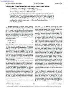
An exhaustive verification tool called Mur' [4, 5] was used to verify the update-based protocols. To verify a protocol using Mur', a description of the system and a behavioral description of the protocol is required. From this, Mur' builds a system state and attempts to traverse it by applying rules from the behavioral description of the protocol. Error statements and invariants are used to detect errors. For example, figure 25 shows the architectural model on which the update-based protocols were verified. The system consists of three caches and one directory/memory. The caches each have one request and one reply buffer, and the directory has four request and one reply buffer. The memory consists of a single line with a two-bit data word. The single line is sufficient since protocols actions do not interact between lines. The single, two-bit data word is also sufficient since if there is a case in which a “wrong” value overwrites a “correct” value then the exhaustive nature of the tool will find the same case for the two values used for the data word. Directory/Memory Request Reply
Order Preserving Network
Request Reply
Request Reply
Request Reply
Cache
Cache
Cache
Processor
Processor
Processor
Figure 25: Verification Model The system state created by Mur', consists of a concatenation of all the state bits in the system. This includes the bits in the cache and memory line data and state information and the message data in the network buffers. In this simple case, this would result in several hundred bits of state, or 2state,bits states, a significant number of states. The actual number of states traversed is dependent on the behavioral rules of the protocol. For the update-based protocols examined, this number quickly consumes all the memory available for the verification since Mur' must remember which states have been visited. There are two techniques to reduce the number of states traversed and, therefore, Mur'’s memory requirements. The first technique is to use symmetry to eliminate redundant states [12, 13]. Symmetry in a system allows Mur' to find states that are equivalent in their current and future behavior with
30 respect to error checking. During verification, only one member of each equivalence class needs to be examined. This technique is able to significantly reduce the total number of states examined. Using symmetry does not affect the correctness or coverage of the protocol verification. The second technique is to limit the number of concurrent actions. Since Mur' is an exhaustive verification tool, every possible combination of events must be verified. Therefore, the more active events, the larger number of traversed states. In the verification of the update-based protocols, the number of outstanding updates was limited to one per cache. Overall, the verification tool was useful in verifying the correctness of the protocols. Errors were detected very quickly, but the state explosion problem limited the size and scope of the verification. As discussed above, the only limitation of the verification that might affect correctness was the limited number of outstanding updates, but the combination of Mur' verification, running simulation with the update-based protocols and hand verification have produced a correct protocol with a high confidence level.
6
Summary
In this paper, the details of two update-based cache coherence protocols were presented. The centralized-directory (CD-UP) protocol was much simpler than the singly-linked distributed directory protocol (DD-UP). The main source of the complexity in the DD-UP resulted from the extra states needed for cache line replacements. In the CD-UP protocol, the path from the directory to a cache was fixed, but in the DD-UP protocol, the path changed as the structure of the list was altered by caches adding and removing themselves from the list. This changing path required the special flushing messages and extra states of the DD-UP protocol. The alternative doubly-linked directory structure might result in a simpler protocol since replacements would be simpler.
31
References [1] Anant Agarwal, Richard Simoni, John Hennessy, and Mark Horowitz. An Evaluation of Directory Schemes for Cache Coherence. In Proceedings of the 15th International Symposium on Computer Architecture, pages 280–289, 1988. [2] David Chaiken, Craig Fields, Kiyoshi Kurihara, and Anant Agarwal. Directory-Based CacheCoherence in Large-Scale Multiprocessors. IEEE Computer, June 1990. [3] David Chaiken, John Kubiatowicz, and Anant Agarwal. LimitLESS Directories: A Scalable Cache Coherence Scheme. In Proceedings of the Fourth International Conference on Architectural Support for Programming Languages and Operating Systems (ASPLOS IV), pages 224–234, 1991. [4] David L. Dill, Andreas J. Drexler, Alan J. Hu, and C. Han Yang. Protocol Verification as a Hardware Design Aid. In Proceedings of the IEEE International Conference on Computer Design: VLSI in Computers and Processors, 1992. [5] Andreas J. Drexler and C. Norris Ip. Mur' Annotated Reference Manual. Stanford University, 1992. [6] Susan J. Eggers and Randy H. Katz. A Characterization of Sharing in Parallel Programs and its Application to Coherency Protocol Evaluation. In Proceedings of the 15th International Symposium on Computer Architecture, pages 373–382, May 1988. [7] David B. Glasco, Bruce A. Delagi, and Michael J. Flynn. The Impact of Cache Coherence Protocols on Systems Using Fine-Grain Data Synchronization. Technical Report CSL-TR94-611, Computer Systems Laboratory, Stanford University, March 1994. [8] David B. Glasco, Bruce A. Delagi, and Michael J. Flynn. Update-Based Cache Coherence Protocols for Scalable Shared-Memory Multiprocessors. In Proceedings of the TwentySeventh Annual Hawaii International Conference on System Sciences, pages 534–545, January 1994. [9] David B. Glasco, Bruce A. Delagi, and Michael J. Flynn. Write Grouping for UpdateBased Cache Coherence Protocols. Technical Report CSL-TR-94-612, Computer Systems Laboratory, Stanford University, March 1994. [10] Anoop Gupta, Wolf-Dietrich Weber, and Todd Mowry. Reducing Memory and Traffic Requirements for Scalable Directory-Based Cache Coherence Schemes. Technical Report No. CSL-TR-90-417, Computer Systems Laboratory, Stanford University, 1990. [11] IEEE Standards Department, 445 Hoes Lane, P.O. Box 1331, Piscataway, NJ 088551331. Scalable Coherent Interface: Logical, Physical and Cache Coherence Specifications, P1596/D2.00 edition, November 1991. [12] C. Norris Ip and David L. Dill. Better Verification Through Symmetry. In Proceedings of the 11th International Symposium on Computer Hardware Description Languages and Their Applications, April 1993.
32 [13] C. Norris Ip and David L. Dill. Efficient Verification of Symmetric Concurrent Systems. In Proceedings of the International Conference on Computer Design: VLSI in Computers and Processors, 1993. [14] John Kubiatowicz and Anant Agarwal. Anatomy of a Message in the Alewife Multiprocessor. In 7th ACM International Conference of Supercomputing, 1993. [15] Daniel Lenoski, James Laudon, Kourosh Gharachorloo, Anoop Gupta, and John Hennessy. The Directory-Based Cache Coherence Protocol for the DASH Multiprocessor. In Proceedings of the 17th International Symposium on Computer Architecture, pages 148–159, May 1990. [16] Brian W. O’Krafka and A. Richard Newton. An Empirical Evaluation of Two MemoryEfficient Directory Methods. In Proceedings of the 17th International Symposium on Computer Architecture, June 1990. [17] Richard Simoni and Mark Horowitz. Dynamic Pointer Allocation for Scalable Cache Coherence Directories. In Proceedings of the International Symposium on Shared Memory Multiprocessing, April 1991. [18] Per Stenstrom. A Survey of Cache Coherence Schemes for Multiprocessors. IEEE Computer, 23(6):12–24, June 1990. [19] Manu Thapar. Cache Coherence for Scalable Shared Memory Multiprocessors. Technical Report CSL-TR-92-522, Computer Systems Laboratory, Stanford University, May 1992. [20] Manu Thapar, Bruce A. Delagi, and Michael J. Flynn. Linked List Cache Coherence for Scalable Shared Memory Multiprocessors. In 7th International Parallel Processing Symposium, April 1993. [21] Wolf-Dietrich Weber and Anoop Gupta. Analysis of Cache Invalidation Patterns in Multiprocessors. In Proceedings of the 3rd International Conference on Architectural Support for Programming Languages and Systems (ASPLOS III), pages 243–256, April 1989.