Hindawi Publishing Corporation VLSI Design Volume 2013, Article ID 425105, 10 pages http://dx.doi.org/10.1155/2013/425105
Research Article Design Example of Useful Memory Latency for Developing a Hazard Preventive Pipeline High-Performance Embedded-Microprocessor Ching-Hwa Cheng Department of Electronic Engineering, Feng-Chia University, 100 Wen-Hwa Road, Taichung, Taiwan Correspondence should be addressed to Ching-Hwa Cheng;
[email protected] Received 27 December 2012; Accepted 22 April 2013 Academic Editor: Yeong-Lin Lai Copyright © 2013 Ching-Hwa Cheng. This is an open access article distributed under the Creative Commons Attribution License, which permits unrestricted use, distribution, and reproduction in any medium, provided the original work is properly cited. The existence of structural, control, and data hazards presents a major challenge in designing an advanced pipeline/superscalar microprocessor. An efficient memory hierarchy cache-RAM-Disk design greatly enhances the microprocessor’s performance. However, there are complex relationships among the memory hierarchy and the functional units in the microprocessor. Most past architectural design simulations focus on the instruction hazard detection/prevention scheme from the viewpoint of function units. This paper emphasizes that additional inboard memory can be well utilized to handle the hazardous conditions. When the instruction meets hazardous issues, the memory latency can be utilized to prevent performance degradation due to the hazard prevention mechanism. By using the proposed technique, a better architectural design can be rapidly validated by an FPGA at the start of the design stage. In this paper, the simulation results prove that our proposed methodology has a better performance and less power consumption compared to the conventional hazard prevention technique.
1. Introduction In current computer architecture, the multiple-instruction (pipeline, superscalar) microprocessors are proposed to improve the efficiency of a single-instruction microprocessor. There are usually four stages (instruction fetch, decode, execute, and writeback) adopted in a multiple-cycle processor. The CPI (cycle per instruction) value of the pipeline (multiple-instruction) microprocessor is several times larger than that of a single-instruction microprocessor. Generally, the pipeline architecture is combined with RISC (reduced instruction set computer) methodology to design high performance processors. Pipeline microprocessor hazards occur when multiple instructions are executed. The pipeline architectural hazards that are introduced in [1, 2] make the program instructions unable to be parallely executed. In general, there are three types of hazards: structure, control, and data hazards. A structural hazard means that the hardware components
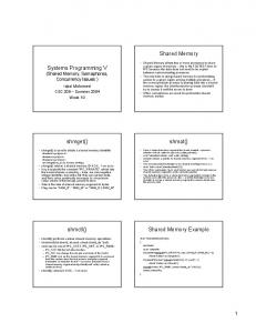
(resources) are insufficient to support the execution of the pipeline instructions in the same clock cycle. The frequently occurring case of the hardware components conflicting when sharing the single port memory means that they are unable to support the read/write operation at the same time. The second type of hazard is termed a control hazard, which arises from the present executed instruction’s inability to make decisions because this instruction decision making should rely on the results from the next following executed instructions. An example is the branch instruction, which is unable to make a correct decision whether to jump or not during this instruction in the execution cycle. This is due to the most recent jump condition can not be obtained when a decision is made. The third type is data hazard occurs when the current instruction’s operands should refer to its earlier instruction’s executing results, but the previous instruction final result is still not stable (the instruction is not working in the writeback stage,) as shown in Figure 1(a) where the reference
2
VLSI Design CK I1
Fetch I2
Decode
Execution
Writeback
Fetch
Fetch
Decode
Execution
Writeback
Fetch
Decode
Execution
I3
(a) Hazard condition
CK I1
Fetch NOP
Decode
Execution
Writeback
Fetch
Fetch
OK Decode
Execution
Writeback
Fetch
Decode
Execution
I2
(b) Hazard prevention by inserting NOP
Figure 1: The conventional hazard prevention technique.
hazard occurred for instructions I1 and I2. The focus of most conventional designs is to analyze the hazard conditions and promote additional mechanism (insert NOP instruction) in order to resolve the hazard situations and obtain better pipeline performance, as shown in Figure 1(b). Memory latency is not welcome because the access delay degrades the microprocessor’s performance. An idea of how to manage the memory latency as a hazard prevention mechanism is shown in Figure 2. There is a half clock cycle memory latency for the fetched instruction which is loaded from the slow-speed main memory (SRAM, DRAM). Hence, the pipeline operation does not need to insert the NOP, and without the performance degradation penalty. The different types of memory in the system board can help designers rapidly create a better pipeline hazard prevention architecture, such as a hazard prevention mechanism that utilizes nonuseful memory latency to reduce the hazard penalty. To design a better pipeline architecture, two factors should be taken into consideration simultaneously. First is the instruction’s hazard conditions, and second is the memory access latency issue. Most of the past architectural designs focus on the instruction hazard detection and prevention scheme from the aspect of pipeline function units. The pipeline-stall and forwarding techniques proposed in [1] are neglecting the use of useful memory latency. The possible reasons may stem from the following: one is that memory requires a particular design for better performance requirement in real microprocessors. This cannot be fully emulated by FPGA. Thus, most of the FPGA is used to verify the functional correctness of the fetch/decode/execution/writeback stages. Freedom of design in different system’s architecture is not available in a chip. Currently, FPGA is utilized to rapidly validate a feasible architectural design. The FPGA emulation process can help designers quickly adopt different memory architectures to reduce the hazard penalties during the system design phase. Better microprocessor performance adopts suitable cache-RAM-Disk memory volume in this hierarchy design. However, there are complex relationships (e.g., levels of cache, RAM access time, and volume) between the memory hierarchy and function units.
In this paper, we propose a superior pipeline architectural design obtained from the FPGA validation phase that does not merely use the FPGA to perform functional verification. As the memory latencies are dissimilar for different types of memory, the idea of an architectural design that applies useful memory latency can be rapidly validated by the FPGA. By choosing to adopt different types of FPGA board memory, we might find a better hazard detection/prevention mechanism. When a designer attempts to utilize different types of memory in the FPGA board, the requirement is to compare the performance when utilizing the different memory latencies (internal register, flash, RAM, or ROM) within the core architecture. We emphasize that the additional onboard memory can be well utilized to handle the hazards. The FPGA board not only helps the designer to validate the function units but also brings creative guidance to help the designer find better architecture and reduce hardware overhead to detect/prevent hazards. One 16-bit X86-light pipeline RISC microprocessor (14 instructions) was developed to validate our idea for specific application (e.g. matrix multiplication). The design is Harvard architecture, where the data and the instruction are put in separate memories. In this paper, we focus on the hazard prevention realistic design using memory latency and verify our results using FPGA implementation for this microprocessor. For demonstrating the different paradigms of solving the hazard problems with/without using the FPGA onboard memory, two design approaches are adopted. Method-1 is the hazard detection and prevention mechanism design using additional hardware. Method-2 uses inboard memory latency to replace the hardware that was proposed in Method-1 and validates the results with a Xilinx FPGA demo board (XESS XSV-800). In the Method-2, the data memory (DM) and instruction memory (IM) SRAM is separate on board for pipeline processor. In this paper, firstly, the data and control hazard detection and prevention techniques (forwarding, NOP insertion, and stall) for our architecture are introduced. Secondly, two validation approaches are used to verify the design architecture. For Method-1, the Instruction-Memory and DataMemory are synthesized and embedded within the design architecture. Method-2 only synthesizes the core architecture into the FPGA and places the Instruction-Memory and DataMemory in SRAM on the board. The test programs need to be loaded into the Instruction-Memory and synthesized with the design at the same time. For Method-2, the test program is loaded from IM and writes output to the Data-Memory during the validation process. Method-2 also supports flexible validation environments for quickly reevaluating the design architecture. There are two contributions of this work. First, for the design phase, memory latency could be effectively utilized to avoid the hazard issues, for designing simpler and faster pipeline architecture; for example, the data hazard resolving mechanisms do not need to be embedded into the design. The second is not the same as conventional designing of the pipeline processor using internal registers as the processor’s IM, DM memory. Using Method-2, the instruction memory
VLSI Design
3 CK I1
Fetch
Decode
I2
Execution OK Fetch + memory-latency Decode I3
Fetch
Writeback
Fetch
Execution
Writeback
Decode
Execution
Figure 2: Using memory latency to design a hazard prevention mechanism.
access latency from on system board SRAM prevents the data hazard problems arising from pipeline operation. The functional testbench does not need to be synthesized with the design, so effortless verification methods can be used to rapidly validate the prototype advanced pipeline core architecture. A more flexible verification environment can be adopted for large amounts of varied test programs. The aforementioned two approaches are successful in evaluating the designs. The synthesizable RISC architecture practically executes 35 MHz onboard, and the clock frequency of Method-2 is two times faster than that of Method-1. As to the organization of this paper, Section 1 comprises the introduction. Section 2 is the design and hazards analysis of our RISC processor. The two FPGA verification methodologies are proposed in Section 3. Section 4 is the experimental results. This paper is concluded in Section 5.
2. The Pipeline Hazard and Memory Latency Surveys In [3], the study investigates the relative memory latency, memory bandwidth, and branch predictability in determining the processor performance. The proposed basic machine model assumes a dynamically scheduled processor with a large number instruction window. This study claims that, if a system with unlimited memory bandwidth and perfect branch predictability, that memory latency is not a significant limit to performance. The simulation model with SPEC92 benchmarks is used to study the performance. Reference [3] proves that the best existing branch prediction mechanism with very large table sizes also resulted in several times lower performance compared to perfect branch prediction method for many benchmarks. This means that perfect branch predict ability is the most import factor. This paper assumes that memory bandwidth is not usually a significant limit for the advanced technology. However, this assumption might not be achievable, as memory bandwidth is always a bottleneck in current harvard system architecture. There are also less currently advanced (multicore with multithread) designs with perfect branch predict ability while to tolerate high memory latency. Reference [4] claims that the repeatable timing is more achievable than predictable timing. This research describes micro pipelining architecture and the memory hierarchy delivers repeatable timing can provide better performance compared to past techniques. The program threads are interleaved in a pipeline to eliminate pipeline hazards, and
a hierarchical memory architecture is outlined which hides memory latencies. In [4], multithread architecture applies the pipeline operation from interleaving the memory access operation. The repeatable timing can speed up pipelining architecture, as the pipeline interleaving is within the pipeline processor and DRAM access. This specific architecture might not be suitable for generic system architecture. The designer applies the proposed technique that needs to consider the instruction dependence conditions. The research [5] reviews the RISC microprocessor architecture, which presents a microthreading approach to RISC microarchitecture. This paper focus on the speculation that has high cost in silicon area and execution time, as a compiler can almost find some instructions in each loop which can be executed prior to the dependency is encountered. The proposed approach attempts to overcome the performance penalty from instruction control (branch, loop) statement and data missing problem. The proposed technique can tolerate high latency memory from avoiding the speculation in instruction execution. However, without well utilizing memory latency, only the compiler cannot obtain the best performance improvement for complicated programs.
3. The Demonstration RISC Microprocessor Architectures The single instruction and the pipeline version demo architectures are written by Verilog HDL and validated using XCV800 Xilinx FPGA [6]. 3.1. The Single Instruction Architecture. Figure 3 shows the microarchitecture of the single instruction version. There are four stages used in this processor, for example, instruction fetch, decode, execute, and write back stages. The next instruction is fetched and should wait until the current instruction’s results are written back to memory (register/data memory). The timing diagrams are shown in Figure 4. There are 4 clock cycles required for each instruction by this style, with each stage of the operation at the clock positive edge. There are partial instructions that do not need to execute the four steps shown in Table 5. The Verilog HDL codes are used to design the hardware function block, and Xilinx FPGA simulation/synthesis environment is used to fulfill the experiments. The single cycle architecture shown in Figure 3 executes the opcode on each clock cycle positive edge. A simple description of the function unit is as follows: instruction
4
VLSI Design using the same registers, for example, RAW (read after write), WAW (write after write). The control hazard is made from the branch instruction, which decides to fetch a false next instruction during the pipeline operation. These hazards have been discussed in previous studies [1, 2].
Figure 3: The single clock cycle architecture.
Fetch
Decode Execute Writeback
Figure 4: The function units are activated by each positive clock edge simultaneously.
memory: store the execution instructions (programs), data memory: store the execution results, PC: program counter, IR: instruction register, rfile: register file, sixteen 16 bit register, and ALU: arithmetic-logic unit. The opcode type-1: instruction of JGE, JMP. The opcode type-2: instruction of AND, OR, NOT, XOR, ADD, SUB, MUL, MOV, CMP. The opcode type-3: instruction of STA, LDA. Each instruction execution is divided into four phases. Fetch: based on the PC value; fetch the instruction from the instruction memory then put it into the Instruction Register (IR). Decode: the MUX selects the proper mathematic/logic operand of ALU. In addition, the operators are offered from different (immediate/direct/indirect) addressing modes. Execute: instruction execution. Writeback: results are written back to the register file. 3.2. The Pipeline Architecture (Method-1). Our pipeline architecture is shown in Figure 5. The instruction/data memory is synthesized using the FPGA internal logic element, and the computed results are obtained in every clock cycle. There are four stages (fetch, decode, execute, and writeback) and three addressing modes (direct, indirect, and immediate) proposed for this design. The results can be obtained after each clock cycle in this four-layer pipeline architecture. The data hazards of pipeline processors are generated from data dependence
3.3. The Hazard Analysis of Pipeline Architecture. Each instruction operation requires 4 clock cycles for Method1. The incorrect pipeline operation occurs when the next instruction is executed in the following clock cycle. These conditions termed the structure, control, and data hazards are occurred. The data hazard was raised from one instruction decoding operation using the same registers that corrupted the previous instructions during the execution (or writeback) stage, for example, the read after write (RAW) data hazard occurring in the pipeline architecture; for example, [SUB r1, r0] follow [ADD r0, #10] and the RAW hazard occurring on the register of r0. The write after write (WAW) hazard causes the register overwrite situation; for example, [STA m[r0], r0] follow [MOV r0, #10]; the register r0 becomes WAW hazard. Thus, the hazard detection and correct circuits were added to resolve these hazard problems in Figure 5. For example, the data hazard occurs when two instructions are executed serially; for example, [SUB r1, r0] follow [ADD r0, #10]; the read after write hazard (RAW) occurs on register of r0. The renew value of r0 = r0+10 was not obtained until the ADD instruction writeback stage. The renew value is not ready to update the source register r0 of SUB instruction during the decode stage. We do not list the other types of hazards in detail such as WAW. The following Figure 6 shows the data hazard occurring on the two instructions of add r0, #10 and add r10, #10. The instruction format is “opcode, target operand, source operand”. There are several types of occurrences that arise from this data hazard issue. We categorize these details in Table 1. The means hazard occurs when the target instruction register (target operand) at the execution stage combines with any third row instruction’s source register (source target) in the decode stage. We just list the simple one here; the other detailed rules are shown in Appendix B. Several types of data hazards are categorized in Appendix C. To resolve this hazard issue, when detecting the aforementioned code sequence, the instruction execution cycle does need to wait for completion (the writeback cycle). The ALU quickly passes the computed results to the next instruction (as the direct input for next instruction). This method is called forward.
4. Memory Latency Utilized by Pipeline Architecture Method-2 Figure 7 shows the pipeline architecture Method-2 changing the instruction/data memory to use the FPGA onboard memory (RAM). The different approaches use these two pipeline architectures for Method-2, and each instruction operation extends to 8 clock cycles. There is no existence of any hazards because the decode/execute/writeback operation in FPGA overlaps with the next instruction access (fetch)
VLSI Design
5
Data
Opcode
Opcode
MUX
Data
MUX
+
PC
1
Address Data
memory
Target Rfile IR memory Source Addmode
Resulth ALU Resultl
Hazard detection unit
Instruction
MUX
Opcode
MUX Addmode
Addmode Fetch stage
Decode stage
Execute stage
Writeback stage
Figure 5: Our X86-light RISC pipeline processor architecture (Method-1).
Add r0, #10 Add r10, r0
Clock PC
00
01
IR
XX
440A
Fetch
Fetch Decode 1
02
03
04
05
4280
7880
4454
40C4
Decode Execute Execute Writeback Writeback 2
Figure 6: The data hazard example. Table 1: Hazard-1. Type-1: RAW. Dependent register
Instruction
EX.Register AND, OR, NOT, XOR, ADD, SUB, MUL, MOV ID.Register.SourceAND, OR, NOT, XOR, ADD, SUB, MUL, MOV
latency from IM (in the demo board). A simpler operating clock cycle is shown in Figure 8. The memory load functional units require four clock cycles, as shown in Figure 8. We use the FPGA experimental board (Xilinx XCV 800) to demonstrate our idea. We focus on using the RAM of this board. There are 4 clock cycles required for SRAM read/write operation of XESS XSV-800 board. The RAM read/write operation requires four clock cycles, and the detailed timing diagram is demonstrated in Figure 9. The memory read/write requires four clock cycles. This gives us the chance to arrange 8 cycles to execute one instruction. There is one do-nothing cycle required to be inserted into the cycle. In total, eight-clock cycle is needed to execute an instruction. The insert do-nothing cycle is used to align the operation of the pipeline instructions. This methodology also has more freedom for hazard prevention. The two-level pipeline has better performance and less
hazard process hardware. The side with simple architecture (no hazard detection circuit required) allows more complex advanced functional cores to be inside. Figure 10 shows the pipeline clock cycle plan of Method2. There are 4 clock cycles required to read instructions from the instruction memory or write results to data memory. We should mention that the signal lines should be ready before the write operation. This is not shown in the figure. The latency can be utilized to cover the timing intervals of one instruction fetch stage with decode/execute/writeback/donothing stages of previous instructions, for example, instructions I2 and I3 in Figure 11. There are no hazards that occur when we move the instruction and data memory outside FPGA to the random access memory on board. The simpler redesign two-layer pipeline architecture is shown in Figure 7. There is no hazard detection/correct circuitry and each output can be obtained at every four clock cycles. If the access delay is not utilized, due to each stage extending to four clock cycles to fit the slowest fetch stage, each instruction operation should expand to 16 clock cycles (4 clock cycles for each stage). However, the hazard problems can be avoided for the four-layer pipeline architecture. Both Method-1 and Method-2 architectures can be adopted and, as we stated, greater flexibility will be available to extend using the onboard RAM. When we need to match the memory read/write cycle, there is one alternation, as shown in Figure 12. All function units extend the operated cycle to four, thus the total clock cycle for executing an instruction increases to 16 clock cycles. In this architecture, the resulting output occurs every four clock cycles. A greater amount of architecture is able to be adopted when there is a sufficient use of different types of onboard memory, such as Flash and ROM. This helps the designer to have more freedom in choosing different design styles. The hazard problem consideration of this architecture is simpler than the no-RAM version, due to each stage having four cycles. Each functional unit in the local element within FPGA only requires one clock cycle to execute the operation.
6
VLSI Design
memory
Opcode
MUX
Opcode Target
Source PC
1
Data
MUX
IR
+
Data
Data
memory Address
Instruction
Rfile
Resulth ALU Resultl
MUX
Addmode
Opcode
Addmode
MUX
Addmode
Fetch stage
Decode stage
Execute stage
Writeback stage
Figure 7: A simpler pipeline architecture without hazard detection/correction units (Mthod-2).
Clock Counter 00
01
02
03
Fetch
IR
04
05
Decode
Execute
06
07
00
Writeback Do-nothing Fetch
Figure 8: The pipeline operation of method-2.
Table 2: There are more benefits from pipeline Method-2. Comparison items Gate count Maximum frequency Maximum net delay
Method-1 69,004 18.766 MHz 18.140 ns
Method-2 47,100 (−31.7%) 30.547 MHz (+62.8%) 16.813 ns (−7.3%)
Table 4: The performance/area comparisons of the synthesis results. Type Single 16-cycle 8-cycle (Method-2)
19.00 MHz 213.40 mW 258.21 mW 210.68 mW
Clock 26.00 MHz 282.14 mW 343.46 mW 278.42 mW
29.00 MHz 311.60 mW 380.00 mW 307.45 mW
Table 3: The design specifications’ comparisons. Type Single
5. The Experimental Result Analysis
Properity Gate count
48656 68926 16-cycle (+41.7%) 47058 8-cycle (Method-2) (+3.2%)
Frequency
Max net delay
26.449 MHz 19.173 MHz (−27.5%) 29.951 MHz (+1.3%)
14.952 ns 18.674 ns (+24.9%) 15.607 ns (+4.3%)
The remaining three cycles (3/4) provide more flexibility to solve the hazard issues than the tight conditions case (each stage assigns one cycle.) Figure 13 shows the data dependence being resolved by the forwarding operation.
In a conventional design concept, an FPGA chip is only used to validate the functional correctness of instruction operations in the fetch/decode/execution/writeback stages. In this research, the FPGA board not only helps the designer to validate the function units but also brings a creative contribution to help find new hazard detection/prevention strategies that have less hardware overhead in comparison to those in the past research. The performance evaluation of a prototype pipeline design needs to utilize different types of memory in the FPGA board as much as possible and to derive a better hazard detection and prevention mechanism. There are four pipes for Method-1 and two pipes for Method-2. Thus, Method-2 has less hardware overhead. Table 2 shows that the synthesis results from Method-2 are
VLSI Design
7 Read wave form Clock Counter
00
01
02
CE
03
04
Read signal enable
05
Read signal disable
OE WE Address bus ready
AddressBus DataOut
Address bus ready Data valid
Logic 0 Logic 1
Figure 9: The read operation timing diagram of XCV800 on board RAM.
Clock Counter 00
01
02
03
04
05
IR1
07
08
0002
0001
PC
06
Fetch 1
10
11
0003
Execute 1 Writeback 1 Do-nothing
Decode 1
IR2
09
Fetch 2
Decode 2
IR3
Execute 2 Writeback 2 Do-nothing
Fetch 3
Figure 10: The clock cycle timing Method-2.
CLK CNT 0
1
PC IR
2
3
0
03 740A
1
2
3
04 7280
Fetch instruction I3 I2 I2 I2 Decode Execute Writeback
7880 Fetch instruction I4
I3 Decode
I3 Execute
I3 Writeback
The SINGLE and 8-cycle version are near equivalent; this represents the pipeline architecture performance is major limited by IM and DM access time. There are several benchmark test bench programs are used for the proposed design. In Table 4, the measure results are obtained from Bubble-Sort for large volume of data. Table 4 measures the power consumption. There is a less power consumption in the 8-cycle pipeline architecture under the three-clock frequency.
Memory Address Enable Data Disable control ready memory ready memory
Figure 11: The three instruction execution cycles of Method-2.
better than those from Method-1. Method-2 works frequency is 62.8% higher than Method-1. Table 3 shows the comparisons of three architectures, and single instruction, 16-cycle pipeline (Figure 12), and 8cycle pipeline (Method-2, Figure 10). All of the specifications are obtained from the synthesized reports by FPGA tool. For equal comparisons, it needs to be mentioned that the three types of instruction/data memory all use the onboard RAM.
6. Discussions In this paper, the proposed pipeline architecture utilizes the memory access latency to improve the performance when hazards occurred. As memory access speed is dissimilar for the different types of memory, well utilize the memory access latency cycles, the pipeline operation can be speed up. The proposed methods use the assumption of instruction and data can be obtained (hit situation) from memory. This means that the instruction and data can be found from the chip’s internal register or onboard memory. These memories are enough to store the required instruction and data during program execution.
8
VLSI Design
Clock Counter
00 01 02 03 04
08 09 10 11 12 13 14 15 16
05 06 07
PC
0001
0002
0003
0004
IR1
Fetch 1
Decode 1
Execute 1
Writeback 1
Fetch 2
Decode 2
Execute 2
Fetch 3
Decode 3
IR2 IR3 IR4
Fetch 4
Figure 12: The alternative pipeline architecture.
Table 5: The instruction set format. (a) Direct/Indirect Address Mode (bit location)
OPCODE 15
ADDMODE 12
11
TARGET
10
SOURCE
9
6
5
NOTHING 2
1
0
(b) Immediately Address Mode (bit location)
OPCODE 15
ADDMODE 12
11
TARGET 10
9
IMMEDICATE 6
5
0
(c)
Instruction Function Direct address mode Immediately address mode Indirect address mode Comments AND AND operation AND R0, R1 AND R0, #10 AND R0, @R1 R0 = R0 ⋅ R1 OR OR operation OR R0, R1 OR R0, #10 OR R0, @R1 R0 = R0 + R1 NOT NOT operation NOT R0 R0 = R0 XOR Exclusive OR XOR R0, R1 XOR R0, #10 XOR R0, @R1 R0 = R0 ⊕ R1 ADD Addition ADD R0, R1 ADD R1, #10 ADD R0, @R1 R0 = R0 + R1 SUB Subtract SUB R0, R1 SUB R0, #10 SUB R0, @R1 R0 = R0 − R1 MUL Multiply MUL R0, R1 {R0, R1} = R0 ∗ R1 MOV Move MOV R0, R1 MOV R0, #10 MOV R0, @R1 R0 ← R1 JMP Jump JMP #10 PC value change JGE Condition jump JGE #10 PC value change CMP Comparison CMP R0, R1 NOP No operation No operation STA Store to memory STA M[R0], R1 STA M[0], R1 M[R0] ← R1 LDA Load from memory LDA R0, M[R1] LDA R0, M[0] R0 ← M[R1]
Clock
Counter
00
01
02
PC
0001
IR1
Fetch 1
IR2
03
04
05
06
07
08
09
10
11
12
13
14
0002
0003
0004
Decode 1
STA
Writeback 1
Fetch 2
Decode 2
LDA
15
16
17
18
0005
Writeback 2
Figure 13: It is not complicated to manipulate the hazard for each stage with four clock cycles.
19
VLSI Design
9 Table 6: The instruction action table.
Instruction JMP CMP JGE NOP STA
Fetch A A A A A
Decode A — A — A
Operation Execution — A — — —
Table 8: Hazard-2. (a) Type-1: RAW
Writeback — — — — —
Dependent register
Instruction
WB.Register ID.Register. Source
AND, OR, NOT, XOR, ADD, SUB, MUL, MOV AND, OR, NOT, XOR, ADD, SUB, MUL, MOV
Ex: ADD r0, #10 → SUB r1, r2 → AND r3, r0, RAW at r0. (b) Type-2: RAW
Table 7: Hazard-1. (a) Type-1: RAW
Dependent register EX.Register ID.Register. Source
Instruction AND, OR, NOT, XOR, ADD, SUB, MUL, MOV AND, OR, NOT, XOR, ADD, SUB, MUL, MOV
The second type of RAW hazard; for example CMP r1, r0 follow ADD r0, #10, RAW occurred onr0. (b) Type-2: RAW
Dependent register
Instruction
EX.Register AND, OR, NOT, XOR, ADD, SUB, MUL, MOV, LDA ID.Register. CMP Source The second type of RAW and WAW hazard; for example, STA m[0], r0 follow ADD r0, #10, RAW occurred on r0; STA m[r0], r1 follow ADD r0, #10, WAW and occurred on r0. (c) Type-3: RAW, WAW
Dependent register EX.Register ID.Register. Source
Instruction
EX.Register ID.Register. Source
Instruction
WB.Register ID.Register.Source
AND, OR, NOT, XOR, ADD, SUB, MUL, MOV, LDA CMP
Ex: ADD r0, #10 → SUB r1, r2 → CMP r3, r0, RAW at r0. (c) Type-3: RAW, WAR
Dependent register
Instruction
WB.Register ID.Register. Source
AND, OR, NOT, XOR, ADD, SUB, MUL, MOV STA, LDA
Ex: ADD r0, #10 → SUB r1, r2 → STA m[0], r0, RAW at r0. (d) ADD r0, #10 → SUB r1, r2 → STA m[r0], r2, WAW at r0
Dependent register
Instruction
WB.Register ID.Register. Source
LDA AND, OR, NOT, XOR, ADD, SUB, MUL, MOV
Ex: LDA r0, m[10] → SUB r1, r2 → ADD r2, r0, RAW at r0.
AND, OR, NOT, XOR, ADD, SUB, MUL, MOV STA, LDA Table 9: Hazard-3. Type-1: RAW, WAW.
(d)
Dependent register
Dependent register
Instruction LDA AND, OR, NOT, XOR, ADD, SUB, MUL, MOV
Dependent register EX.Register ID.Register.Source
Instruction LDA STA
Ex: LDA r0, m[1] → STA m[2], r0, RAW at r0. LDA r0, m[1] → STA m[r0], r1, WAW at r0.
The third type RAW data hazard will occur as the following example ADD r1, r0 follow LDA r0, m[10] occurred on the r0. (e) Type-4: RAW
Dependent register
Instruction
WB.Register EX.Register
AND, OR, NOT, XOR, ADD, SUB, MUL, MOV AND, OR, NOT, XOR, ADD, SUB, MUL, MOV
The third type RAW data hazard will occur as the following example ADD r1, r0 follow SUB r1, r0, RAW occurred on the r0.
The designer applies the proposed concept to obtain a better system architecture in preplan stage. Form well arranging this memory latency situation with pipeline instruction in
fetch/decode/execution/writeback state. The proposed nature system behavior can obtain a better pipeline performance, which can be easily implemented in a system memory structure with fixed latency. When instruction and data missing situations occur, it means that the instruction and data access time might length, and the pipeline operation need to be varied under this consideration. The proposed methods need to be modified by waiting for more cycles for the instruction and data enter ready state under instruction and data missing situations. In the future study, a reliable system need to consider the instruction and data missing situation. Hence, the proposed Method-1,2 need to be modified for inserting different
10
VLSI Design
wait cycles for instruction and data memory missing situations. A flexible system architecture requires to include the instruction and data hit-miss conditions for various memory architectures. However, such a pipeline architecture is hard to design by including different memory waiting cycles.
Hazard-1.
7. Conclusion
Hazard-2.
We find that a good cycle timing plan is the most important issue for designing a pipeline CPU. The processor performance depends on how well the clock cycle, the control, and the data flow are managed. Also, the design style has a good chance to be improved if one does consider that the memory latency can be utilized for hazard prevention. When the microprocessor can utilize different types of memory (internal register, flash, RAM, or ROM) in the system board, this gives flexibility and helps to achieve a system architecture with better performance. The hard to use onboard memory will be regularly ignored during the prototype verification phase. The designer should not forget the onboard FPGA memory, although it differs from the real CPU memory, and it is also inconvenient to use it (to coordinate the read/write operation with kernel function units). This might be the best chance to reevaluate the preliminary design during the verification phase because one might find another better hazard free structure from memory latency. In our experience, the designer can obtain a greater number of different architectures by spending time to try to use onboard memory. The functional test program should take the memory access delay into consideration when the execution programs are moved to the outside memory in the second method. The design that applies memory latency for hazard prevention has a better performance with less power consumption than that of the conventional design.
Appendices A. There are 14 instructions supported in this design; the details of the fourteen instruction formats are shown in Table 5. The partial instructions might not operate at all functional stages as shown in Table 6. The symbol A means the instruction has an action on this stage, and — means the instruction has no operation in this stage.
B. The hazard condition could regulate listing as the following rules. The explanation of the Hazard-1 condition is the source operand (in instruction decode stage) using same register with the previous instruction target register (operand) in the execution stage. Hazard-2 and Hazard-3 are described as the former description. However, the hazard condition is different for pipeline architecture Method-1 and Method2. All three hazard conditions will occur only with pipeline Method-1, but pipeline Method-2 only has Hazard-1 and Hazard-2 (no Hazard-1) occurring.
if ((ID.RegisterSource = EX.Register) or (EX.Register = WB.Register)). Hardware Solution: hazard detection unit-Forward.
if ((ID.RegisterSource = WB.Register)). Hardware Solution: hazard detection unit-Forward. Hazard-3. if ((ID.Instruction. Sta = EX.Inxtruction. Lda) and (ID.RegisterSource = EX.Register)). Software Solution: insert NOP Instruction.
C. We categorize the data hazard conditions to interpret the data utilization error occurring at different stages. Condition 1 is control/data hazard occurring on Tables 7, 8, and 9.
References [1] D. A. Patterson and J. L. Hennessy, Computer Organization and Design, M.K. Publishers, 1998. [2] J. L. Hennessy and D. A. Patterson, Computer Architecture—A Quantitative Approach, M.K. Publishers, 2003. [3] N. P. Jouppi and R. Parthasarathy, “The relative importance of memory latency, bandwidth, and branch limits to performance,” in Proceedings of the Workshop on Mixing Logic and DRAM: Chips That Compute and Remember, 1997. [4] S. A. Edwards, S. Kim, E. A. Lee, I. Liu, H. D. Patel, and M. Schoeberl, “A disruptive computer design idea: architectures with repeatable timing,” in Proceedings of the IEEE International Conference on Computer Design (ICCD ’09), pp. 54–59, Lake Tahoe, Calif, USA, October 2009. [5] C. Jesshope and B. Luo, “Micro-threading: a new approach to future RISC computer,” in Proceedings of the 5th Australasian Architecture Conference, 2000. [6] http://www.xess.com.
International Journal of
Rotating Machinery
Engineering Journal of
Hindawi Publishing Corporation http://www.hindawi.com
Volume 2014
The Scientific World Journal Hindawi Publishing Corporation http://www.hindawi.com
Volume 2014
International Journal of
Distributed Sensor Networks
Journal of
Sensors Hindawi Publishing Corporation http://www.hindawi.com
Volume 2014
Hindawi Publishing Corporation http://www.hindawi.com
Volume 2014
Hindawi Publishing Corporation http://www.hindawi.com
Volume 2014
Journal of
Control Science and Engineering
Advances in
Civil Engineering Hindawi Publishing Corporation http://www.hindawi.com
Hindawi Publishing Corporation http://www.hindawi.com
Volume 2014
Volume 2014
Submit your manuscripts at http://www.hindawi.com Journal of
Journal of
Electrical and Computer Engineering
Robotics Hindawi Publishing Corporation http://www.hindawi.com
Hindawi Publishing Corporation http://www.hindawi.com
Volume 2014
Volume 2014
VLSI Design Advances in OptoElectronics
International Journal of
Navigation and Observation Hindawi Publishing Corporation http://www.hindawi.com
Volume 2014
Hindawi Publishing Corporation http://www.hindawi.com
Hindawi Publishing Corporation http://www.hindawi.com
Chemical Engineering Hindawi Publishing Corporation http://www.hindawi.com
Volume 2014
Volume 2014
Active and Passive Electronic Components
Antennas and Propagation Hindawi Publishing Corporation http://www.hindawi.com
Aerospace Engineering
Hindawi Publishing Corporation http://www.hindawi.com
Volume 2014
Hindawi Publishing Corporation http://www.hindawi.com
Volume 2014
Volume 2014
International Journal of
International Journal of
International Journal of
Modelling & Simulation in Engineering
Volume 2014
Hindawi Publishing Corporation http://www.hindawi.com
Volume 2014
Shock and Vibration Hindawi Publishing Corporation http://www.hindawi.com
Volume 2014
Advances in
Acoustics and Vibration Hindawi Publishing Corporation http://www.hindawi.com
Volume 2014