Design & Implementation of IEEE 802.11s Mesh Nodes with enhanced features Pranjal Pandey, S.Satish, Joy Kuri, Haresh Dagale Centre for Electronics Design and Technology, Indian Insitute of Science, Bangalore, India
[email protected],
[email protected], {kuri, haresh}@cedt.iisc.ernet.in
Abstract—This paper describes the implementation of wireless mesh nodes based on the IEEE 802.11s draft where the motivation is to build a real life mesh network. The mesh nodes developed have mesh, mesh access point and mesh portal functionalities simultaneously. The mesh nodes use different radios for mesh and access point functionalities, thus giving better service to client stations. Both reactive and proactive modes of HWMP are supported. The paper also suggests some measures to enhance the performance of the overall network by reducing the number of PREQs. Keywords-IEEE 802.11s, Wireless Mesh Network (WMN), Hybrid Wireless Mesh Protocol (HWMP).
I. I NTRODUCTION Wireless Mesh Networks (WMN) offer an inexpensive, quickly deployable, stable and fault tolerant solution for wireless coverage, requiring zero maintenance. Due to these benefits, WMNs have received considerable attention from both the academia as well as the industry. The WMN based on 802.11 is most popular due to easily available and inexpensive radios. There are currently many implementations of wireless mesh network based on 802.11 hardware. All of these run some proprietary mesh protocol at network layer. To produce a standard for 802.11 based mesh networks, task group ’s’ has been set up by IEEE 802.11. We have designed and implemented 802.11s based wireless mesh nodes which are capable of real life deployment. Our work is based on open80211s 0.2.1 [1] which is an open source reference implementation of 802.11s draft standard for Linux. The important additions made to existing code in open80211s include: • Implementation of Proactive HWMP • Implementation of 6 address scheme • Interworking with stations outside MBSS • Integration of MP, MAP and MPP in same node Some of the points which distinguish our work from previous such works [2] are as follows: (a) The mesh nodes have a single virtual interface for mesh network [1], (b) The mesh protocol is implemented as a kernel module and works closely with the device drivers, (c) Use of 6 address frame format. The rest of the paper is organized as follows. First, a brief overview of the IEEE 802.11s draft is presented in Section 2. Section 3 then gives details of the implementation and Section 4 presents some observations and suggestions. c 978-1-4244-5113-5/09/$25.00 2009 IEEE
In Section 5, the tests and measurements carried out using the implemented mesh network are discussed. The paper is concluded in Section 6. II. IEEE 802.11 S The task group 802.11s set by IEEE has been working for the mesh amendment to the 802.11 standard. At the time of this work, the most recent draft was P802.11s D3.0 [3]. This section gives an introduction to 802.11s features and enhancements which are relevant to our work. A. Mesh Basic Service Set (MBSS) Independent Basic Service Set (IBSS) and Infrastructure Basic Service Set (Infra-BSS) are the two Basic Service Sets (BSS) defined by IEEE 802.11 standard. To these, IEEE 802.11s adds a third type of network topology called Mesh Basic Service Set or MBSS. An MBSS can have the following three different kind of entities. • Mesh Station or mesh STA • Mesh Access Point or MAP • Mesh Portal or MPP Mesh STA is the necessary component for a BSS to qualify as MBSS. It is a normal 802.11 STA with added features of frame forwarding and path discovery. As the MPs(Mesh Points) exchange frames at the MAC layer which is transparent to the Logical Link Control (LLC) Layer, the MPs form a single broadcast domain. When an MP also has an access point functionality collocated with it, it is called Mesh Access Point or MAP. A Mesh Portal or MPP has the frame forwarding capability over non-802.11 networks like 802.3. Thus different type of networks can be interconnected using wireless mesh networks. B. Path Selection Algorithm and Link Metric IEEE 802.11s specifies the Hybrid Wireless Mesh Protocol (HWMP) as the mandatory Path Selection protocol. HWMP runs at the MAC layer and has following two modes of operation. • On Demand (Reactive) Mode • Proactive Tree Building Mode Both these modes can also be used simultaneously. The On Demand Mode is based on AODV [4]. But, unlike AODV, it works at layer 2. It uses three different types of management frames, viz.: Path Request (PREQ),
Path Reply (PREP) and Path Error (PERR). The working of the on demand mode is depicted in Fig. 1. When MP4 has some data for MP9, it initiates broadcast PREQ frames seeking a path for MP9. Every time an MP originates PREQ, it increments the sequence number to indicate a fresh PREQ frame. These PREQ frames may reach MP9 through different paths. An MP accepts a received PREQ/ PREP frame only if it carries a higher sequence number or if it offers a better airtime metric [3], [5] with same sequence number compared to the one present in the path table. If the PREQ/PREP frame is accepted by the intermediate MP, it updates its path table, adds last hop airtime link metric to the path metric in PREQ/PREP frame and forwards it. When these PREQs reach MP9, MP9 selects the path with lowest metric and sends a unicast Path Reply (PREP) frame back. Thus MP4 and MP9 establish a bidirectional path, MP4−MP7−MP9 (say). In the Proactive mode of HWMP, one of the MPs
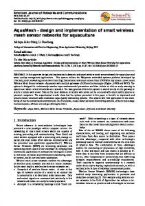
Figure 2.
802.11 frame format with Mesh header
normal 802.11 STA. The 2 bit Address Extension Flag (AE) indicates which of the three address pairs are present in the mesh control field. The Mesh Address Extension is required in MBSS as three different source destination pairs can exist. These pairs can be: (1) One Hop away transmitter [ADD2] and receiver [ADD1], (2) Mesh Path source [ADD4] and Destination [ADD3], and (3) End to End source [ADD6] and destination [ADD5]. D. Interworking and Proxy Mechanism
Figure 1.
Path Discovery using On-Demand Mode
acts as the ROOT node. The ROOT periodically broadcasts proactive PREQ frames. The target address field of proactive PREQ is set to all ’1’. Thus every MP forwards these PREQs and sends PREP back to ROOT. Alternatively, the ROOT can also send Root Announcement (RANN) frames, on receipt of which the MPs may initiate PREQ to ROOT. So, finally, the ROOT gets paths to all MPs present in the MBSS and vice versa. Thus, the proactive tree is built. In case of the proactive mode, if a node does not have a path for a destination, it sends the frame to ROOT and ROOT then forwards the frame to destination. In hybrid mode, both proactive and reactive components act concurrently. While forwarding the frame, ROOT also indicates that the source is within the MBSS and so the destination initiates PREQ for the source of the frame. C. Frame Format and 6 Address Scheme 802.11s adds a mesh control field to the 802.11 frame as shown in Fig. 2. The mesh control field starts after the normal 802.11 header and is interpreted as payload by a
Interworking of MBSS with other LANs is achieved using the 6 address data frames, Portal Announcement frames and Proxy mechanism. All portals send periodic portal announcement frames to other MPs. Thus when an MP has a data for some station for which it can not find a path, it will send the data frame to all portals. A mesh STA who proxies for 802 entities outside the MBSS is called a proxy mesh STA. A Proxy Mesh STA can convey the proxied MAC addresses to other MPs using Proxy Update (PU) frame. The receiver of a PU frame updates its path table and sends a Proxy Update Confirmation (PUC) frame back to originator of PU. The 802.11s implementation should support the 802.1D bridge so that the bridge can learn and forward packets on to its mesh port. Different bridges can communicate through MBSS to participate in bridge protocols like the Spanning Tree protocol. III. I MPLEMENTATION DETAILS A. Hardware Details Router Board RB433ah based on the Atheros AR7161 processor running at 680 MHz, was chosen as the target platform for implementing a mesh node. Each mesh node uses one Ethernet port (for MPP) and two radios (one for MAP functionality and other for MP). Atheros’ AR5413 a/b/g chipset based mini- PCI cards (WLM54AGP23) were used as radios. The antennas used had omni-directional radiation pattern with 5dBi gain. Fig. 3 shows an installed mesh node and the node Internals respectively. The nodes are powered from ac mains. B. Software Architecture The software implementation was done on Linux (kernel 2.6.28.5) using OpenWRT’s Kamikaze 8.09 [6] distribution.
All the data frame handling for AP interface is done by mac80211. The Mesh, AP and LAN interfaces are bridged together using ’brctl’. Brctl is the 802.1D bridge utility in Linux. C. Implementation
Figure 3.
Installed Mesh Node & Mesh Node Internals
’mac80211’ [7] was chosen as the wireless stack to implement mesh network due to its extensive driver support. It also supports virtual mesh interface using Open80211s Mesh Implementation. Open80211s 0.2.1 has components like Peer Link Management, On-Demand HWMP, Airtime Link Metric and supports only MP functionality. Our work is mainly focused on proactive HWMP and the interworking of MBSS with other networks. As each node has to support MP, MAP and MPP functionalities, extensive additions and modifications were made to the existing mac80211. The modifications include optimization of mesh path table and support for new management frames. The complete software architecture is shown in Fig. 4. As
Figure 4.
Software Architecture for the Mesh Node
’mac80211’ does not have full support for AP interface in itself, it needs a user space daemon called ’hostapd’ for AP support. When a STA is associated or disassociated, hostapd updates the list of associated STAs present in mac80211.
A simple mesh network interconnecting three wired LANs is shown in Fig. 5. All the nodes operate in IEEE 802.11g band. Nodes 3, 4 & 5 have collocated MAP as well. This topology will be used to explain the mesh node implementation. All the nodes use the same channel for mesh functionality and a different non-overlapping channel for access point functionality. Any mesh node can be configured to act as ROOT of the network. A ROOT node periodically sends proactive PREQ. In case there is more than one node configured as ROOT, a mesh node will receive proactive PREQs with different originator mac addresses. The mesh node then sets the lowest originator mac address as the ROOT. All mesh nodes configured to act as ROOT, upon receiving proactive PREQ with lower originator mac address, stop sending proactive PREQ and set the originator of the proactive PREQ with lower MAC address as the ROOT. So finally there remains a single ROOT node which sends proactive PREQs and has paths to all nodes within the MBSS. In Fig. 5, node 1 is the ROOT node. The proactive tree built by ROOT is shown by bold dashed links. When a mesh node (say node 3) does not have path for the destination (say node 5), it sends a 6 address frame to ROOT. The ROOT node then forwards the frame to node 5 via node 4. ROOT sets a flag (VIA_ROOT) in the frame to indicate that the frame is forwarded by ROOT [3]. Here, it should be noted that add6 of the frame can as well be a station outside MBSS (like STA1). In HWMP, there may exist many non-bidirectional paths. By non-bidirectional path between two nodes X and Y, we mean node X has a path for Y but Y either does not have a path for X or has a different path for X (not the same as the one X has for Y). The origin of non-bidirectional paths is explained as follows. In HWMP the PREQ frames traverse in all directions and every MP receiving the PREQ may add/update path for the originator. But the originator adds path only for the target of the PREQ frame. Similarly all intermediate nodes receiving the PREP frame add/update path for the target address but the target only adds/updates path for the originator and not for the intermediate nodes. To indicate whether a node has a bidirectional path for another node, a flag (bidirectional flag, BDF) is maintained for every path in the path table. The target sets the BDF of originator’s path to ’1’ when it initiates a PREP for that originator. Similarly, the originator sets the BDF of target’s path to ’1’ when it receives the PREP. The need for this flag is explained later. In Fig. 5, consider the case that node 2 has a path for
node 5 through node 3, but node 5 does not have a path for node 2. Now if node 2 sends data to node 5 through node 3 and node 5 has to reply back, node 5 will send the frame first to ROOT. But if node 5 and the intermediate nodes (in this case, node 3) are allowed to update the path for node 2 on receiving the data packet (which is not part of 802.11s draft), it can send the reply back to node 2 through node 3. To implement the access point functionality collocated with an MP, the AP interface is bridged with the MP interface. When a station gets associated/ disassociated with the access point and the list of associated stations is updated, the mesh interface sends a ’Proxy Update (PU)’ frame to ROOT. This is possible only when the driver for MP radio and MAP radio use mac80211 stack. So, the ROOT instantly knows about the ’proxy mesh node’ for a station when it associates to an MAP for the first time or it moves from one MAP to another. Similarly the portal functionality was implemented by bridging the Ethernet interface with the mesh interface. All nodes configured as portal periodically send Portal Announcement (PANN) frames to ROOT. If the mesh interface has to send PU frame for the stations in the wired LAN, for every frame it receives from the bridge, it has to check if the frame was originally received by an Ethernet interface. It also needs to check if a ’PU’ has already been sent for the address 2 of the frame. This requires a list of stations present in the LAN to be maintained by the mesh interface. This can avoided if the mesh nodes are allowed to add path using the 6 address frame they receive. To update the path information using the 6 address frame, the node first checks if add4 and add6 are different and then adds add4 as the proxy mesh station for add6. When ROOT receives a frame for a station outside the MBSS for which it has a path, it forwards the frame to the ’proxy’ for the outside station. It also sends the proxy information to the mesh path source of the frame. If it does not have a path, it forwards the frame to all portals. To explain the interworking between wired LANs, MBSS and the IBSS, we consider the following two cases: 1) Communication between an MP and a station outside the MBSS: Suppose the station STA3 wants to communicate to node 2. If node 5 has a path for node 2, it will forward the frame to node 2. When node 2 receives the frame, it adds node 5 as the proxy for STA3. If node 2 does not have a path for node 5 it also initiates PREQ for it. But if node 5 does not have path for node 2, it will send the frame to ROOT and ROOT forwards the frame to node 2. ROOT will also add node 5 as proxy for STA3. In that case, node 2 first sends PREQ frame for node 5 and then adds node 5 as proxy for STA3. Similarly when the node 2 wants to communicate to STA3 and it does not have a path, it will send the frame to ROOT. ROOT will forward the frame to node 5 and also
Figure 5.
Test Setup
send a PU back to node 2 if it has a path for STA3. After receiving PU from ROOT, node 2 will first initiate a PREQ for node 5 (only if either it does not have a path for node 5 or the BDF flag for the path is ’0’). Node 2 then adds node 5 as the proxy for STA3. Then onwards, node 2 will send the frame for STA3 to node 5. 2) Communication between external stations: Suppose STA3 wants to communicate to STA7. If node 5 does not have path for STA7, it will send the frame to ROOT. ROOT will add a path for STA3 through node 5, if it does not already have one. If ROOT does not have a path for STA7, it will forward the frame to all portals except node 5 (in this case only node 3). ROOT also sends the frame to the upper layer (bridge). When node 3 receives the frame from ROOT (via_root=’1’), being a portal, it should not add path for STA3 now. [This is done so that the first frame from STA7 goes through ROOT and ROOT can add a path for STA7. So, ROOT can send PU when some other STA wants to communicate to STA7.] All subsequent frames from STA3 to STA7 follow the same path until STA7 sends a reply back. When STA7 replies to STA3, node 3 sends the frame to ROOT. ROOT then adds node 3 as proxy for STA7 and forwards the frame only to node 5. ROOT also sends a PU (to reach STA3) back to node 3. When node 3 receives the PU from ROOT, it initiates PREQ for node 5 if either it does not have a path to node 5 or the BDF flag is ’0’. Node 3 also adds node 5 as proxy for STA3 and then onwards sends the frames for STA3 to node 5. When node 5 receives a frame from STA7 directly from node 3 (via_root=’0’), it adds node 3 as proxy for STA7. In case the destination station is associated with an MAP,
ROOT will send PU to the source MP immediately. This is because ROOT always has updated path information for all stations associated with MAPs. IV. I SSUES AND O BSERVATIONS WITH 802.11 S As PREQ frames are always sent to the broadcast address, they result is severe flooding over the entire MBSS. This gets even worse if we add to it the fact that multicast frames are sent at the basic transmit rate (1 Mbps for 802.11g). This is because the receivers of the frames may not support the high rate either due hardware limitation or poor link quality. So the number of PREQ frames in the MBSS should be as low as possible. In our implementation, mesh nodes never initiate PREQ for a station outside the MBSS. Instead, ROOT unicasts the proxy information to the node when required. This is possible because ROOT maintains the path for all external stations from whom ROOT has either received or to whom ROOT has forwarded a frame. Thus the number of PREQs is minimized. We suggest a mechanism of controlled flooding of PREQ named as ’Limited PREQ’. This mechanism minimizes the impact of PREQs by controlling the TTL value of PREQ frames. Normally the TTL value is set to a value which will assure that the PREQ frame can traverse the whole MBSS. But this may not be required as the target can sometimes be very close to the originator. So, if the originator knows the approximate number of hops to target, it can set the TTL of PREQ appropriately. This can be implemented by adding a ’hop_count’ field in the mesh header. Now, suppose node 5 in Fig. 5 has a path for node 2 but node 2 does not have a path for node 5. So node 5 can directly send the frame to node 2. When node 2 receives the frame from node 5, it also comes to know the number of hops to node 5. This information can be used while initiating the PREQ for node 5. But if node 5 also does not have path for node 2, the frame from node 5 will then reach node 2 through ROOT. After receiving this frame (via_root=’1’), node 2 can initiate PREQ with the TTL equal to ’hop count’ present in the received frame. If the originator does not receive PREP, the TTL value of next PREQ can be made twice the previous value. The hop count of the path should be saved and any PREQ sent to refresh the path, should use the same hop count. This mechanism is similar to the ’expanding ring search’(ERS) discussed in [4]. But unlike ERS, where the initial TTL value of PREQ frames is static, Limited PREQ mechanism learns the initial TTL value from the network (if possible). As the benefit of ’Limited PREQ’ mechanism will be evident only in big networks, results are not available. V. T ESTS AND VALIDATION The Test Bed is same as the network shown in Fig. 5. All the mesh nodes are in the interference range of one another.
Figure 6.
Snap Shot of GUI
An ’ncurses’ based program was written to graphically display the present proactive tree structure. ’mac80211’ passes the list of immediate children to user space through debugfs interface. A small UDP client program running on the mesh node, sends this information to ROOT. ROOT (a desktop machine) displays the results on terminal using ncurses package. Fig. 6 shows a snapshot of the graphical display. Also a mac layer utility was developed to trace the path for a desired destination mac. Fig. 7 shows the path traced from node 1 to node 3. Fig. 8 shows Ethereal capture of the frame sequence when
Figure 7.
Figure 8.
Snap Shot of the Path Trace
Ethereal Capture of ping request from node 5 to node 3
node 5 communicates to node 3. Here node 5 does not have path for node 3 and so the first ping request frame is sent to
the ROOT. Frames inside the box show how the first ’ping request’ from node 5 reaches node 3 through intermediate nodes. It also shows the corresponding ACK frames. The path followed can be traced using the receiver address of the ACK frames. Here, source and destination addresses are same for all the four data frames as Ethereal displays only the end-to-end source and destination addresses. Node 3 then initiates PREQs and after getting PREP frames, sends the ping reply directly to node 5. Throughput measurements (using iperf) done on the
Figure 10.
Link throughput vs number of PREQs per second
hops when single radio single channel mesh nodes are used. Future work will concentrate on design and development of multi-radio (with respect to MP) wireless mesh node and incorporating congestion control schemes. In particular, we are interested in dual radio mesh stations. Improvements to hardware include the addition of battery backup and deploying higher gain antennas. Figure 9.
Throughput vs hopcount
testbed network are shown in Fig. 9 as bar graphs. The light grey bars represent the throughput between the two mesh STAs A and B when they are ’N’ hops away from each other. The dark grey bars represent the throughput between the mesh STA A and the STA P (associated to MAP B) through MAP B. Since MAP B has separate radio for mesh and access point functionalities, both the radios can be active simultaneously in different channels. So an extra wireless hop from MAP B to STA P should not degrade the overall throughput. As expected, for a given number of mesh hops between mesh STAs A and B, the throughput from A to P (dark bars) and the throughput from A to B (light bars) have a very small difference. The impact of PREQ flooding on throughput is shown in Fig. 10. This experiment was done on a different setup having 5 nodes. One node was programmed to send PREQs periodically and the throughput between two neighbouring nodes (one hop away) was measured. VI. C ONCLUSION We have implemented 802.11s based single radio and single channel (with respect to MP) wireless mesh nodes which are capable of real life deployment. Based on the tests and measurements carried out using the developed nodes, several issues which can degrade the performance are pointed out and a possible solution is also presented. It is observed that throughput degrades with the number of
R EFERENCES [1] Open source implementation of ieee 80211s. [Online]. Available: http://open80211s.org [2] D. I. L. T. Rosario G. Garroppo, Stefano Giordano, “Notes on implementing a ieee 802.11s mesh point,” in 4th International Workshop of the EuroNGI/EuroFGI Network of Excellence, Barcelona, Jan. 2008. [3] Draft Standard for Information Technology - Telecommunications and Information Exchange Between Systems - LAN/MAN Specific Requirements - Part 11: Wireless Medium Access Control (MAC) and physical layer (PHY) specifications: Amendment: ESS Mesh Networking, IEEE draft P802.11s/D3.0, March 2009. [4] E. B. R. C. Perkins and S.Das, “Ad hoc on-demand distance vector (aodv) routing,” IETF Std. 3561, http://tools.ietf.org/html/rfc3561, Jul. 2003. [5] R. G.R.Hiertz, S.Max, “Principles of ieee 802.11s,” in Proc. of 16th International Conference on Computer Communications and Networks (ICCCN), 2007. [6] Linux distribution for embedded devices. [Online]. Available: http://openwrt.org/ [7] Linux api to write softmac wireless drivers. [Online]. Available: http://linuxwireless.org/