system development framework. K. M. Goh ... testing of the framework through the development of a prototype. ... Microprocessor, FPGA and Application Specific.
SIMTech technical reports (STR_V10_N3_04_MEC)
Volume 10 Number 3 Jul-Sep 2009
Design of a new IEC 61499-based embedded system development framework K. M. Goh, and B. Tjahjono1
Abstract – Developing an embedded software solution can be time consuming and challenging. Traditionally, embedded software is programmed manually in proprietary computer languages such as C, C++, Java and assembly languages. In addition, most of the embedded software design environments do not cater for both microprocessors-based and Field Programmable Gate Array (FPGA) based embedded platforms. This paper proposes s a conceptual design of a new embedded system code generator framework which is based on the IEC61499 Function Block to address the code generation issues. This involves the design and testing of the framework through the development of a prototype.
some of the subset embedded computer languages like SystemC, HandelC, and SpecC. A formal method for various embedded systems platforms is therefore needed in order to facilitate a more effective and efficient development of embedded systems solutions. The International Electrotechnical Commission (IEC) has proposed the IEC 61499 standard [1] which provides a modelling method aimed at manufacturing and automation domain experts. The standard allows encapsulation of control logic into function blocks that represent sequence of execution, based on process state, communication, control, event and dataflow using both networks and composite function blocks. Although the IEC 61499, to a large extent, has been endorsed by automation and manufacturing engineers [2], it does not address the lower level embedded system software issues such as the limited definitions in handling the low level code generation. The overall purpose of the work described in this paper is therefore to explore the use of the IEC 61499 as a formal method for embedded systems and to extend its capability to address the aforementioned issues within the embedded systems design framework.
Keywords: FPGA, IEC 61499, Function block, Code generator
1
BACKGROUND
An embedded system is a special-purpose, small size hardware device and software system commonly used in standalone products or added on to other equipment to enhance their functionalities. Examples include consumer products and industrial control equipment often found in manufacturing or aerospace sectors. By using embedded systems, both complexity and flexibility of equipment can be fulfilled mainly because embedded systems developers need to focus only on specific functions requested in order to optimise the solution. Developing an embedded software solution is a challenging task and can be time consuming especially for non-software trained engineers such as control engineers. Most of the non-software trained engineers or stakeholders cannot participate in the design and development of embedded system. Traditionally, software that runs on an embedded system is programmed manually in various proprietary computer languages such as C, C++, Java and assembly languages, and the executable file is downloaded onto the hardware. This means the developers of embedded systems have to be familiar with many proprietary computer languages to support multiple embedded platforms. However, these proprietary languages are not compatible with each other, making it difficult to reuse the source codes. For example, although C and C++ are similar, they are not fully compatible with 1
2
OBJECTIVE
The overall objective of this research is to investigate how International Electrotechnical Commission (IEC) 61499 can be extended to address the lower level code generation issues, thus facilitating the development of embedded systems solution. The investigation involves the design of the development environment and testing the framework through the use of a proof of concept. The outcome has demonstrated that the framework provides a flexible development environment that could be use together with new or existing tools within the embedded systems development tool chain. 3
RELATED RESEARCH
3.1
Embedded System Environments
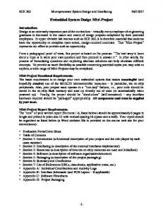
Embedded systems are typically developed using Microprocessor, FPGA and Application Specific Integrated Circuits (ASIC) hardware platforms. Figure 1 shows the different types of embedded systems development processes, design methodologies, tools and approaches for microprocessor, FPGA and ASIC.
School of Applied Science, Cranfield University, United Kingdom
144
K. M. Goh, and B. Tjahjono
ASIC design methodologies involve a wide variety of complex tasks in the placement and routing step, such as placement of circuit and physical optimisation, clock tree synthesis, signal integrity and routing. In the placement and routing step, both FPGA and ASIC development processes consist of defining the design specifications such as Input/Output standards, memory requirements and selection of hardware and platform. At the compilation step, different FPGA and ASIC vendors support different Input/Output standards and different numbers of Input/Output pins. Vendors will provide specific tools for their own products. FPGA and ASIC are generally developed using low level languages such as Verilog and VHDL (Very high speed integrated circuit Hardware Description Language) for RTL (Register Transfer Level) coding, specification of the external and internal memory. High level languages such as SystemC and Handel C are commonly used for both platforms. Currently, there are no design tools, methodologies or standards for FPGA and ASIC design at the systems level. Most of the designers will focus on single chip level design and do not consider reusabil-
ity and distributed solutions, because the designers tend to have a very specific knowledge on low level gates, I/Os and electronics circuits rather than systems level application. Compared to FPGA and ASIC, microprocessor development is similar to PC-based applications which produce object files and usually invoke the linker after compiling to provide linking object files and library files to form an executable file. The executable file provides instructions to control the sequence of logic in the microprocessor. UML is commonly used as the systems level design tool for PC-based software design. Operational functions are described in class diagrams, use case diagrams, and UML software tools translate them into the high level programming languages such as C++ or Java. For each compilation in the microprocessor-based development environment, a binary file is produced. After the compilation, the linker is usually invoked to link the library files into an executable file. The compiled microprocessor program controls the sequence of the logic gates, which is used to write data into data buses, latches and registers and across channels.
Fig. 1. Comparison of microprocessors, FPGA and ASIC development process (adapted from [3,4]).
3.2
Related Research
Research at the systems level design for embedded systems has been one of the key areas in recent years. A literature review in this area has categorised them into UML based, IEC 61499 based and others. 3.2.1
UML Based Methodologies
UML is a well known modelling method for PC-based software solutions. Many researchers (for
145
example [5-8]) extended the UML standard by using XML as an intermediate language to convert UML design to either SystemC or HDL for a single processor environment. In addition, Kangas et al [9] further explored UML as a modelling method for multiprocessor and FPGA environments. The above shows that there is a lot of interest in using software engineering-based modelling methodologies for FPGA application.
Design of a new IEC 61499-based embedded system development framework
The adoption of XML shows that the research is moving towards open standards. UML is commonly used for modelling and design of software systems as it comprises a collection of diagrams used for software design specifications. However, UML lacks representation for gates, I/Os, timing as well as distributing and interconnecting through multiple controllers. As a consequence, new diagrams and representations are needed to enhance the UML standards for FPGA-based embedded systems. In a survey by Graaf [10], it was found that UML is not the common practice adopted by most embedded system developers. Projects that employed diagrams are mostly using free-form and box-line diagrams. 3.2.2
a system level design using open standard, XML-alike tools for embedded system. The aforementioned work has been exploring XML as an intermediate language for code generation. However, IEC 61499 based development environment for FPGA based embedded system is still lacking. Future research should therefore be focusing on IEC 61499-based embedded system development environment for both FPGA and microprocessor that would make the development environment more accessible by industrial engineers and thereby increasing the adoption of embedded systems within manufacturing industries. 4
IEC 61499 Based Environment
The Open Object-Oriented kNowledge Economy in Intelligent inDustrial Automation (OOONEIDA or O3NEIDA) initiated research on reconfigurable industrial control and automation objects [2]. It strongly supports the IEC 61499 Function Block. Woll [11] claimed that IEC 61499 is “simple, cost effective and repeatable’ to meet the industry demand of mass customisation and 24/7 industry”. Thramboulidis et al [12] developed the Common Object-Oriented Real-Time Framework for Unified Development (CORFU) Engineering Support System (ESS) to translate UML to IEC 61499 and to generate Java code for embedded controller, although it does not address the need for the FPGA-based embedded systems. In addition, there is a publicly available free Function Block Development Kit (FBDK) [13] for IEC 61499 development environment written in Java. Although FBDK can generate XML and Java codes, it neither generates C or C++ codes nor addresses FPGA-based embedded platforms. The only commercial product that uses IEC 61499 is ISaGRAF [14] but it does not interoperate with FBDK, CORFU. In addition, it does not support FPGA-based environments. There is a lot of research focusing on the microprocessor-based development environments, the semantics, modelling and verification using IEC 61499 [15-20]. In addition, Zoitl et al [20] summarised that most of the current research is on design and execution environment, definition of semantics, application scenarios and coding tools. Most of the IEC 61499 tools are for microprocessors-based solutions and do not address other types of embedded controllers including FPGA or hybrid of FPGA and Microprocessor. 3.2.3
PROPOSED DESIGN FRAMEWORK
OF
THE
As mentioned earlier, this paper proposes an embedded development framework for both microprocessor and FPGA using industry standard methodologies that are suitable for industrial engineers. Figure 2 shows the proposed framework. The following subsections will briefly describe the components of the framework. E
requirements
A
stylesheet structuring stylesheet
B
common modules for specific application
G
stylesheet C
templates and reference designs
D
F
Fig. 2. Proposed IEC-based embedded system development framework.
Requirements (Stage A): This stage captures the technical and application requirements from the users (industrial engineers). There are numerous software engineering methodologies and tools available that can be used at this stage, for instance UML. IEC 61499 is another industrial automation standard that is explored in this research. Structuring (Stage B): This stage aims to convert the system requirements into various hardware and software components, systems level architecture and reusable components structure. These components will become the building blocks for the application. The components could be FPGA-based, microprocessor-based or a combination of both. Each component will have its functions, attributes, interface and control.
Other Methodologies
Statecharts and Petri Nets have also been explored as code generator by many researchers, for example [22-25]. Gomes et al [23-24] use Petri Nets as a modelling method to capture the design and to convert XML-based intermediate language to C and potentially VHDL. The research interest is to provide
146
K. M. Goh, and B. Tjahjono
Templates and reference design (Stage C): This is a repository of various style definition sheets, software templates, reference design and implementation, either from past implementation or from other external sources. The functionality needs to be encapsulated into reusable portable blocks. Style sheets define the style of the target application languages such as C, HTML, C++, or VHDL languages. Style sheets will allow potential code generators to generate the source codes. The templates and reference designs can be reconfigured to new users’ application requirements. This will help in speeding up the development cycle. Hardware/software partitioning and rapid application generation (Stage D): In this stage, system designers are required to decide which part of the components should be developed using hardware-based, software-based or a hybrid approach. The application generator that generates the codes will be based on the style sheet and the requirements specification. Reconfigurable hardware based solution (Stage E): In this stage, the use of Field Programmable Gate Arrays (FPGA), a chip that has many reconfigurable logic gates, is proposed. The FPGA gates can be configured into various circuits. Some of the circuits can be processed in parallel in order to speed up complex algorithm computation. This solution is more affordable nowadays as the cost of the FPGA chip has dropped significantly over the last few years and it is suitable for computational intensive processing. Microprocessor-based solution (Stage F): This solution is similar to a PC-based solution embedded in a small device with a smaller microprocessor. It requires an operating system and a software application. The system could also have databases, web servers, or standard software applications such as desktop computers. The only drawback of this solution is that the processing depends on the speed of the microprocessor, which could be much slower than PCs. Specific applications (Stage G): The final applications could be, once again, an FPGA-based embedded system, a microprocessor-based embedded system or a combination of both. The system will be small in size and ready to add on to existing machines or equipment. Prognostics services (Stage H): The embedded application could be in the form of a small box, added on to the equipment or it could be standalone or handheld. The embedded solution can have various sensors and algorithms to process raw data at the source and it can also communicate with other systems. 5
THE DEVELOPMENT ENVIRONMENT
Figure 3 shows the development environment and the tools chain for the proposed conceptual framework.
147
Physical System BNF definition of the computer language Stage A, B: Function Blocks Stage C: YACC XML XSL Style definition Stage D: Parser
Stage E: High level code e.g. SystemC
C, C++, Java
Stage F: Microprocessor
HDL Translator
Verilog/VHDL
Synthesis HDL
Stage E: FPGA
Fig. 3. Proof of concept environment.
Stage A is the stage where the technical and application requirements from the users are captured. Stage B is the structuring stage which aims to convert the system requirements into the system level architecture. The first two stages can be addressed by IEC 61499 Function Block. Stage C, the templates and reference design stage, can use yet another compiler, Compiler (YACC), to convert Backus-Naur Forms (BNF) representation of the computer language into XSL style sheet. Stage D is the parser stage which can be addressed by XML and XSL parser to generate source code. Stage E is to generate source code for FPGA which can be addressed by generating SystemC codes or other high level codes such as Impulse C and Handel C. Various commercial and open source tools can convert high level C codes into Verilog for FPGA. Stage F could be addressed by generating source codes in C, C++ or Java which are the common embedded system languages. In our proof of concept, we will be using simple light switches to demonstrate an application that can be controlled by FPGA. 5.1
IEC 61499 Function Blocks
IEC has defined various standards for industrial automation. IEC 61499 is the component-based open standard function block model that helps both the design functionality of the system and the integration of various systems. Function block shares many features with Unified Modelling Language (UML) objects. Objects may contain data which are also instances of other objects. Likewise, function blocks may contain instances of other function blocks. Objects can be used for invocation with the methods with arguments and return values. Meanwhile function blocks use input and output variables and events. Data can be synchronised with events in function blocks. It can be used for capturing both current and future system requirements as in Stage A and can also be used as building blocks for applications.
Design of a new IEC 61499-based embedded system development framework
. The template is then tested against every node in XML document. If a match is found then the content of the template is generated as output. Once matched, the child nodes will not be considered unless an explicit instruction is given. The element can be used to extract the value of an XML element and that value can be added to the output stream of the transformation. The element is used to select every XML element between the start tag and the end tag. Figure 5 shows the XML file generated by the Function Block.
Non-software industrial system specialists who are familiar with connecting physical devices together can use these encapsulated function blocks, link them together to develop the system solutions. Function Blocks can be easily used for modelling a wide range of manufacturing problems and solutions ranging from small scale logic gates to large scale distributed systems. A function block is a ‘functional unit of software application’ that has its own internal data and algorithms. Function blocks allow functions to run on different resources so that distributed control systems can be constructed. Smaller elementary function blocks can be created like software libraries and can be interconnected into larger function blocks for more complex problems. 5.2
eXtended Markup Language (XML)
XML is an open, simple, flexible text format originally designed for a large-scale electronic publishing. XML is standardised by World Wide Web Consortium (W3C) and is jointly developed by IBM, Microsoft and Sun Micro Systems. In this paper, XML is used as the meta-language to define the set the function block. The XML format has flexible features which support easier custom code development or code generators in application development using corresponding parser to convert XML format into other textual formats. 5.3
eXtended (XSL)
Style
Sheet
Fig. 4. XSL for various language formats.
Language
XSL is the customisable interpreter for XML documents which describes the styles and formatting for XML documents and provides how the XML documents should be presented. By applying XSL on the XML data, formatted documents can be generated depending on a particular need. XSL contains three parts for XML documents such as XSL Transformation (XSLT), XML Path Language (Xpath) and XSL Formatting Objects (XSL-FO). XSLT is used for transforming the XML documents, which includes built-in template rules to copy the text element content from a source tree to a result tree. XPath is used to navigate and XSL_FO is used to format XML documents respectively. XML is a widely accepted industry standard of a universal data format for exchange data. XSL formats the style of XML documents that could be used as a template for code generator for variety of languages shown in Fig. 4. XSL documents start with syntax which declares version number of the of XML documents to be manipulated by XSL and the text encoding scheme. The next line, indicates that this document is an XSL style sheet format. The ‘match’ attribute is used to define a template and to associate that template with an XML element. The value of the match attribute is defined by an XPath expression, for example:
Fig. 5. XML document for OR operation.
Since the XSL is used to manipulate the XML documents where information is stored, conditional tests against the expression can be done in XSL documents. There are several XML elements available to do the conditional tests. The element is one of the elements that allows conditional testing in XSL. In order to use , test conditions must be provided as the attribute of the element. If the test condition is true then the next element inside the conditional test element will be executed. Multiple conditional tests can be done with and elements together with the element. Figure 6 shows the XSL template that help the XML parser generate the C codes.
148
K. M. Goh, and B. Tjahjono
timing, concurrency and reactive behaviours. Figure 7 shows IEC 61499 Function Block can be used as the system level design tool. IEC 61499 generate difference languages for various embedded environment. SystemC is used instead of Verilog because SystemC allows designs to be expressed and verified at high levels of abstraction and implemented in the lower level hardware. This approach helps system designer to design and simulate both the hardware and software behaviours of the system. Requirements
Generate
Architecture
HW/SW Functional Verification System C
XML Parser
Test Bench
XML parser can be used together with XML and XSL to generate codes in C++, Verilog, SystemC and Java languages. There are many XML parsers available. The simplest one is the plain string parser which treats the XML document as a string content and returns element values by sensing the presence of < and /> within that string. XML documents are manipulated by the XML parser which loads the document into computer's memory and then the data can be manipulated using the Document Object Model (DOM). DOM is a hierarchical way to represent the elements in an XML document and accesses them like a tree. A simple API for XML (SAX) is an alternative to DOM. SAX opens up possibilities for using the XML document. As each element, or node occurrence, is parsed and triggered as a resulting event in the application, it can be interpreted in the way the application requires so that SAX can provide a special representation method. Some popular SAX and DOM parsers are Megginson (Java-based SAX parser) [26], Aelfred (Java-based SAX parser) [27] and Microsoft's DOM parser [28]. Megginson parser is an open source application and is free to use. It is used as the API to access the XML document in Java and has become the standard API to access the XML document in Java. The latest version of Megginson parser supports SAX version 2.0 and is available for various programming languages. Aelfred is a lightweight XML parser for Java. Aelfred SAX parser is also known as the variation of Megginson SAX parser. Microsoft XML parser is available for any programming language which supports the Microsoft ActiveX technologies. 5.5
Java C, C++
Fig. 6. XSL to convert XML to C.
5.4
IEC 61499 Function Block
SystemC
SystemC is an open standard system modelling language that supports hardware/software co-design and co-simulation using C++. SystemC is used in both electronic and non-electronic systems designs. It can provide higher levels of abstraction for all system components and the advantages of C++ class library constructs with
149
Verilog
RTL
Gates
Transistors
Fig. 7. Language comparison.
6
PROOF OF CONCEPT IMPLEMENTATION
This section presents the proof of concept of IEC 61499-based implementation that will generate SystemC codes which will subsequently be converted to Verilog for FPGA. For simplicity, a switch and light system [29] is used to model and simulate using IEC 61499 function blocks. 6.1
Switch and Light System
Switch1 and Switch2 are the inputs and Light1 and Light2 are the outputs. In this system, Light1 and Light2 will be ON when Switch1 is turned ON while Switch2 is OFF. Only Light1 will be ON when both Switch1 and Switch2 are turned ON. Since Switch1 is the main switch, when Switch1 is turned OFF, both lights will be OFF. Boolean logic, such as AND and NOT operators, is used in order to implement this system. The logic is: Light1 = Switch1 Light2 = Switch1 AND Switch2 The system is modelled using a network of basic function blocks. The switch and light control system will be controlled by NOT and AND function blocks which are the main function block of the network. The model has 7 function blocks: START, (Switch) IN_ BOOL, (Light) OUT_BOOL, NOT and AND as shown in Fig. 8.
Design of a new IEC 61499-based embedded system development framework
the resulting format of the XML. Software developers can create XSL style sheet to define the required language template. As shown in Fig. 6, XML parser (e.g. Microsoft’s MSXSL) can process the XML source and convert it to the target language based on the XSL. 7.1
Compile and Simulate SystemC
The START function block shown in Fig. 9, is necessary for the system. This block is used to control the start and stop of the chain of function blocks. The E_RESTART block has only three start events: COLD, WARM and STOP. The COLD start event is used to initially start the system and the WARM start event is used to restart the system after it has already been started. The STOP event is used to end the system. E_RESTART block is usually the first function block in the network of function blocks since it is controlling the start and stop of the system. Figure 10 depicts the time sequence diagram for COLD, WARM and STOP of E_RESTART function block respectively.
By using Microsoft Visual C++ or other compilers, the header and system files can be compiled into an executable file. The compiler needs to link the SystemC header file (SystemC.h) and the library file (SystemC.lib) with the Run-Time Type Information (RTTI) enabled. RTTI provides the run time type information of dynamic variables that are necessary for systems which are using dynamic variable with multiple inheritances and dynamic type casting as well as the template classes. SystemC library files are heavily dependent on the Run Time Type Information. The executable file will show output in console but will not be accurate as a real system due to the existence of the delta delay problem in SystemC which is commonly found in embedded systems. To solve this problem, tf=sc_create_vcd_trace_file ("sl_trace") needs to be added into the SystemC testbench to generate the Value Change Dump (VCD) files that can be viewed in a wave form viewer (e.g. SystemC Win) as shown in Fig. 10. A VCD file is an ASCII file which consists of header information, variable definitions and the value changes for all variables specified in the task calls. VCD is a standard format that is compatible with many waveform viewers. The VCD file eliminates the need to know the internal logic of the system.
Fig. 9. Testing switch and light system.
Fig. 11. Simulated digital wave form.
7
7.2
Fig. 8. Function blocks of the switch and light system.
6.2
START Function Block
GENERATION OF SYSTEMC USING XML AND XSL
Verilog Code Generation
SystemC is the hardware modelling language based on the C++ language. SystemC provides the APIs and the simulation kernel to design and test electronic systems with high level of abstraction. However SystemC is a new hardware modelling language and the tools to convert SystemC into Electronic Data Interchange Format (EDIF) for FPGA are still lacking. It is therefore necessary to convert SystemC into other hardware description languages such as Verilog. This is because Verilog has been supported as the hardware description language for many years and there are numerous tools available to convert Verilog into EDIF.
Most embedded system programmers will have to master many computer languages such as C, C++ and Java which consequently needs extensive training. Many embedded systems have proprietary programming languages. Code generation can give a better solution for engineers who are not expert in programming languages. They can use function block to ‘draw’ and ‘link’ the application and code generator will then generate the right source codes according to the embedded system language requirements. Choosing the right tool to perform code generation is critical. XML is the metafile for web and data representation and XSL is the style sheet that defines
150
K. M. Goh, and B. Tjahjono
The SC2V (SystemC to Verilog) [30] converter is a software tool which translates the SystemC source codes into the Verilog-equivalent ones. SC2V is based on the Lexical Analyzer Generator (LEX) and Yet Another Compiler-Compiler (YACC). LEX is a lexical processor for character input streams whereas YACC uses the code generated by the LEX and builds the parse tree. SC2V checks whether the input program is syntactically correct or not. Both LEX and YACC are the fundamental component for compiler construction. SC2V it is an open source tool but it does not support In/Out ports and global variables for SystemC and, at the moment, it can only support a very limited data type for SystemC such as bool, sc_int, sc_bigint, sc_uint and sc_biguint. SC2V does not allow any C standard data types such as int, char, long and etc. Each module must have a header file with .h format including the declarations of ports, signals, processes and there must be a .cpp file which includes the implementation code of the processes. There are some expensive commercial tools available to convert SystemC to Verilog. They are Forte Cynthesizer [31], Synopsys Cocentric System Studio [32] and Agility Compiler [33]. Once the Verilog file is generated, it could be easily converted into Electronic Data Interchange Format (EDIF) using the development environment from FPGA’s vendor, e.g. Xilinx’s ISE, to do the placement, routing and BIT file for configuring the FPGA chip. Figure 11 shows the Switch and Light System on a XLINIX Spartan FPGA Board.
A simple case of switch and light system has been modelled in function blocks using the FBDK tool which supports XML. In this case, the various language formats are defined by the XSL style sheet to generate source codes for both microprocessor-based (e.g. C++, C, Java) and FPGA-based (e.g. SystemC). In order to implement the control system on FPGA, the switch and light system must be in HDL format because it is the only format capable of describing the circuit’s operation, design and organisation, in order to test and verify the operation by means of simulation. Among many hardware description languages, Verilog is chosen because there are a number of both free and commercial tools available to synthesize and route to FPGA. The function block is found to be more user-friendly for non-software specialists to design embedded systems compared to learning different programming languages and to manually code the systems. As this research is still in an early stage, there are some limitations of the IEC 61944. First, the designer still needs to deal with many parameters and interface points in complex design. Second, the IEC 61499 does not define the detail of the metadata representation which may cause compatibility issues between different tools. Third, existing commercial tools are not cost effective whereas freeware tools chain are not integrated, not fully tested and not user friendly. There is a potential improvement for a fully integrated tool chain. There are more research opportunities in areas such as the automated partition and optimisation code from IEC 61499 to microprocessor-based, FPGA-based on hybrid solution, the automated style sheet creation, as well as the automated conversion from the traditional source codes to function block components. 9
Fig. 11 Testing switch and light system on Spartan FPGA board.
8
CONCLUSIONS RESEARCH
AND
INDUSTRIAL SIGNIFICANCE
The framework provides a flexible embedded software development environment that could be use together with new or existing tools within the tool chain. It facilitate a more effective and efficient development of embedded systems solutions for industries.
FUTURE REFERENCES
In this paper, an embedded system development framework has been proposed and a proof of concept case study has been discussed. The framework adopts the IEC 61499 for systems level design and XML/ XSL standards for source codes generation. It also includes the BNF to XSL-based style sheet definition for different computer languages, a code generator that generates different source codes and a converter from SystemC source codes to Verilog codes for FPGA-based embedded systems. The framework provides a flexible embedded software development environment that could be use together with new or existing tools within the tool chain.
151
[1] IEC, “IEC 61499 Industrial-Process Measurement and Control Specification”, IEC Technical Committee TC65/WG6, IEC Draft, 2000. [2] V.V. Vyatkin, J.H. Christensen, J.L.M. Lastra, “OOONEIDA: An Open, Object-Oriented Knowledge Economy for Intelligent Industrial Automation”, IEEE Trans. Ind. Inform., vol. 1(1), pp. 4-17, 2005. [3] N. Aslam, “A low-cost solution for FPGA-based PCI Express Implementation”, http://www.pldesignline. com/shared/article/showArticle.jhtml?articleId=18700 3208, 09 March 2007. [4] Ed Klingman, “FPGA programming step by step”, http://www.embedded.com/showArticle.jhtml?articleI D=18201956, 07 September 2006.
Design of a new IEC 61499-based embedded system development framework
[5] F.P. Coyle and M.A. Thornton, “From UML to HDL: a Model Driven Architectural Approach to Hardware-Software Co-Design”, Inform. Sys.: New Generations Conf., 4-6 April 2005, pp. 88-93. [6] Y. Wang, X.G. Zhou, B. Zhou, L. Liang, C.L. Peng, “A MDA based SoC Modelling Approach using UML and SystemC”, Proc. IEEE Int. Conf. Comput. Inform. Technol., 2006. [7] W.H. Tan , P.S. Thiagarajan , W.F. Wong , Y. Zhu and S.K. Pilakkat, “Synthesizable SystemC Code from UML Models”, Int. Workshop UML for SoC Design (USOC 2004), June 2004. [8] K.D. Nguyen, P.S. Thiagarajan and W.F. Wong, “A UML-based Design Framework for Time-triggered Applications”, IEEE Real-Time sys. Sympo., Arizona, USA, December 2007. [9] T. Kangas, P. Kukkala, H. Orsila, E. Salminen, M. Hännikäinen, T.D. Hämäläinen, J. Riihimäki and K. Kuusilinna, “UML-based Multi-Processor SoC Design Framework”, ACM Trans. Embedded Computing Sys., vol. 5(2), pp. 281-320, 2007. [10] B. Graaf, M. Lormans, H. Toetenel, “Embedded Software Engineering: The State of the Practice”, IEEE Comput. Soc. IEEE Software, vol. 20(6), pp. 61-69, 2003. [11] D. Woll, “Setting the Stage for the Next Generation of Automation Control System Software: A Discussion of IEC 61499”, http://www.arcweb.com/Featured%20 Research/IEC-61499-Ins13M.pdf, 10 October 2007. [12] K. Thramboulidis, “Model-integrated mechatronics toward a new paradigm in the development of manufacturing systems”, IEEE Trans. Ind. Inform., vol. 1(1), pp. 54- 61, 2005. [13] http://www.holobloc.com/ [14] ICS Triplex ISaGRAF http://www.icstriplex.com/ [15] http://www.uni-magdeburg.de/iaf/cvs/torero/ [16] http://www.microns.org/ [17] M. Khalgui, X. Rebeuf, F. Simonot-Lion, “A behaviour model for IEC 61499 function blocks”, Third Workshop on Modelling of Objects, Components and Agents (MOCA'04), 2004, pp. 71-87. [18] K. Thramboulidis, “IEC 61499 in Factory Automation”, Adv. Comput. Inform. Sys. Sci. Eng., pp. 115-124, 2006.
[19] V. Dubinin, V. Vyatkin, “Towards a Formal Semantic Model of IEC 61499 Function Blocks”, IEEE Int. Conf. Ind. Inform. (INDIN), Singapore, August 2006. [20] V. Dubinin, V. Vyatkin, and H.M. Hanisch, “Modelling and Verification of IEC 61499 Applications using Prolog”, 11th IEEE Conf. ETFA, Prague, September, 2006. [21] Zoitl, T. Strasser, K. Hall, R. Staron, C. Sünder and B. Favre-Bulle, “The Past, Present and Future of IEC 61499”, Lecture Notes in Computer Science: Holonic and Multi-Agent Systems for Manufacturing, vol. 4659/2007, Springer Berlin, 2007, pp. 1-14. [22] M. Mura, M. Paolieri, L. Negri and M. G. Sami, “StateCharts to systemc: a high level hardware simulation approach”, Proc. Great Lakes Sympo. VLSI, Maggiore, Italy, 2007, pp. 505-508. [23] L. Gomes, J.P. Barros and A. Costa, “Structuring Mechanisms in Petri Net Models: From specification to FPGA based implementations”, Design of embedded control systems, Kluwer, 2004. [24] R. Nunes, L. Gomes, Barros, “A Graphical Editor for the Input-Output Place-Transition Petri Net Class”, 12th IEEE Int. Conf. ETFA, 25-28 September 2007, pp. 788-791. [25] N. Hagge and B. Wagner, “A New Function Block Modelling Language Based on Petri Nets for Automatic Code generation”, IEEE Trans. Ind. Inform., vol. 1(4), pp. 226-237, 2005. [26] http://www.megginson.com/ [27] http://saxon.sourceforge.net/aelfred.html [28] http://msdn.microsoft.com/xml/ [29] J. Fischer and T.O. Boucher, ‘Workbook for Designing Distributed Control Applications using Rockwell Automation’s HOLOBLOC Prototyping Software”, Working paper, pp. 05-17. [30] http://www.opencores.org/projects.cgi/web/sc2v [31] http://www.forteds.com/products/cynthesizer.asp [32] http://www.synopsys.com/products/designware/sys tem_studio/system_studio.htm [33] http//www.celoxica.com/products/agility/default. asp
152