Another Workflow Language (YAWL) has been defined by extending the Petri Nets formalism with several features in order to overcome the limitations of Petri ...
Design of a Petri Net-Based Workflow Engine Simone Pellegrini, Francesco Giacomini INFN Cnaf Viale Berti Pichat, 6/2 - 40127 Bologna, Italy {simone.pellegrini | francesco.giacomini }@cnaf.infn.it
Abstract Several years of research are establishing Petri Nets as a modeling formalism for scientific workflows; their formal semantics and the existence of several analysis tools, among others, make them suitable for complex concurrent processes’ description. However, the non-determinism of the Petri Net model clashes with the imperative Turingbased environment provided by mainstream programming languages such as C/C++, Java and C#. Therefore several design decisions must be taken in order to provide a concrete implementation of a Petri Net-based engine. This paper proposes the architecture of a workflow engine – currently implemented in a Workflow Management System (WfMS) – with the goal to provide a reliable and efficient platform for the execution of scientific workflows in a Grid environment. One of the design principle is the neutrality towards the underlying mechanisms for task execution, in order not to compromise interoperability with multiple infrastructures.
1. Introduction Workflows are gaining a lot of interest both in the business and scientific environments for automating the execution of complex IT processes. Workflow programming model is very appealing for unskilled end users because it allows to express the business logic behind such processes usually in a graph-oriented high-level way, leaving the management of low level details to a WfMS. Furthermore, composition tools exist in order to aid the workflow design process, hiding most of the underlying details related, for example, to the internal representation. As a consequence, several workflow description languages, at different levels of complexity, have been defined. These languages are based on different modeling formalisms such as: Directed Acyclic Graphs (DAGs), πCalculus [1], UML Activity Diagrams [2] and Petri Nets. Unfortunately, the existence of a variety of languages and
formalisms makes interoperability between different platforms very challenging, and consequently penalizes the use of workflows. DAGs are often used in the description of simple scientific processes because of their simplicity and the ability to model the data-flow. Furthermore, DAGs can describe the control-flow in terms of sequence, parallelism and choice but not iteration, limiting the expressiveness of such formalism. More powerful than DAGs, the Turing-complete Petri Nets formalism deals with both the control and data-flow allowing the description of complex concurrent processes. Recent studies [3] have demonstrated that the modeling capabilities of Petri Nets outperform other formalisms mainly thanks to the following properties [4]: (i) the formal semantics despite the graphical nature, (ii) state-based structure (as opposed to the event-based one, on which π-Calculus is based), and (iii) the availability of many analysis techniques. Lately, many efforts have been done in order to propose a workflow description language based on the Petri Nets formalism. For example, the Grid Workflow Description Language (GWorkflowDL) – which has been introduced by the Fraunhofer FIRST research group – is an XML-based language which uses the High Level Petri Nets (HLPN) modeling formalism [5] [6]. In the business environment, the Yet Another Workflow Language (YAWL) has been defined by extending the Petri Nets formalism with several features in order to overcome the limitations of Petri Nets in describing business processes [7]. Although the stated superiority of Petri Nets in workflow modeling, both in scientific and business environments, only few workflow enactment engines based on such formalism exist, namely GWES and YAWL. In fact the power of Petri Nets comes at the price of non-trivial implementations, which have to deal with all the theoretical aspects of the formal model, first of all non-determinism. Although avoiding non-determinism in the design of a workflow is a good practice, this is not always possible and the way the engine copes with it should not affect the workflow execution result. As of today, there are no clear guidelines on
how a Petri Net-based workflow engine has to be implemented. In fact, several design choices have to be taken in order to implement such engine in the Turing-based environment provided by the common imperative programming languages such as C/C++ and Java. For instance, the behavioral details of the Grid Workflow Execution Service (GWES), probably the currently most used implementation, are available only looking at the source code. In this paper we present the design of an engine based on HLPNs. The static architecture and its dynamic behavior are both described to show how problems related to the execution of a Petri Net can be addressed. The engine natively uses the HLPNs formalism as internal representation making it possible to (i) formally represent the workflow state (and its evolution); and (ii) deal with adaptive and dynamic workflows which represent one of the main challenges in the next-generation WfMSs [8]. The goal of this work is to introduce a reference implementation of an engine usable in environments where Petri Nets are commonly employed, such as workflows, simulations and scheduling. As a proof of concept, the engine has been implemented as part of a WfMS developed with the purpose to support the execution of Petri Net-based workflows (written in the GWorkflowDL language) on the EGEE/gLite Grid middleware [9], which is deployed on a large and mature infrastructure. Sect. 2 introduces the UML class diagram that formally models the mathematical definition of Petri Nets in an Object Oriented Programming (OOP) paradigm. In Sect. 3 problems related to the Petri Nets dynamic behavior are considered by analyzing the selection and firing of transitions and also the sub-workflow execution mechanism. In Sect. 4 we present some implementation details and how the interaction with the gLite Grid middleware is made possible. Sect. 5 presents how this work will progress in the future.
2. From HLPN to the OOP model The semantic model of an HLPN can be described in several ways [10]. An HLPN is normally represented using a graphical form which allows visualization of system dynamics (flows of data and control). An HLPN can be defined by the tuple: HLP N = (P, T, T ype, P re, P ost, E, G, M0 ) where: • P is a finite set of elements called Places; • T is a finite set of elements called Transitions, disjoint from P (P ∩ T = ∅); • T ype is a function that assigns a type to places and expressions;
p1 : P lace < String >
p4 : P lace < String >
b b : V ar < String > c : V ar < Int >
a : V ar < Int > [a! = 0] 3 0
c = a + len(b)
p2 : P lace < Int >
p3 : P lace < Int >
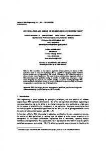
Figure 1. A Petri Net based workflow
• P re ⊆ (P × T ) is the subset of arcs from places to transitions and P ost ⊆ (T × P ) is the set of arcs from transitions to places; • E is an arc expression. It is defined from P re ∪ P ost into expressions. Expressions may comprise constants, variables (e.g., x, y) and functions (e.g., f (x)) which are typed; • G is the Guard function, a boolean expression inscribing a transition t ∈ T (where T ype(G(t)) = boolean); • M0 is the initial marking: a multiset of tokens associated with the places. According to the mathematical representation, transitions are atomic operations that, when fired, consume tokens from the input places and put tokens – according to edge expressions – into the output places. Considering the workflows application domain, an edge expression is often represented by a task execution, which generally can fail. Therefore, when multiple expressions are associated with a transition it is difficult to guarantee the atomicity of their execution (either each expression terminates successfully or no expression executes). When expressions have side effects, the overall workflow state could be easily compromised. In order to avoid edge expressions and, consequently, make failure management easier, the HLPN model has been simplified: only variables can be associated with edges and expressions are moved into transitions. This simplification does not limit the expressiveness of the HLPN model; in fact it is simple to prove that an edge expression can always be replaced by a transition which performs the same operation. However, this approach can lead to an increase in the number of transitions in the workflow description, a problem which is mitigated by the sub-Petri Net execution mechanism shown in Sect. 4.
According to the changes done to the formal HLPN model, a Petri Net-based workflow can be represented as depicted in Fig. 1. Each place is marked with a type (using a parametric programming syntax style). Edges are identified by variables, where a variable type must be compatible with the input (if the edge e ∈ P × T ) or output (if edge e ∈ T × P ) place. Also tokens have a type: in Fig. 1 gray tokens are of Integer type and the black token is of String type. The boolean transition condition (the Guard) is defined in square brackets. Expressions are associated with transitions. In the general case, expressions can have several return values, compatible with the number and type of the variables associated with the output edges of the transition. However, in this implementation we consider the common situation where the output edges of a transition are labeled with variables which are either defined in the incoming edges or in the expression. For example, the b variable in Fig. 1 is used to copy the token consumed from place p1 into the output place p4 ; while the c variable, which is defined in the transition expression, is used to store the result of the computation performed during the transition firing. The simplified HLPN model can be easily represented in a OOP language as depicted in the class diagram in Fig. 2. According to the theory, places, tokens and variables have a type; in order to keep type constrains in the OOP model, parametric programming – which is available in most of mainstream programming languages (C++, Java and C#) – is used. Variables, modeled by the Var class, are associated with edges. Operations and conditions, associated with transitions, are implemented using the Function class. The Function and Var classes represent the basic concepts of the model. The Function class allows to express the static relationships between a transition operation (or condition) and the transition input and output places (identified by edge variables). A Function instance is a placeholder for the invocation of a procedure – whose signature is in the form T f(P1 p1,...,PN pn) – whose arguments p1,...,pn are the values of the tokens that, at runtime, trigger the transition. According to the model simplification, operations can have only one return value; however this is not a limitation as far as multiple return values can be provided using a Tuple object as return type. However, the number and type of the parameters associated with an operation is unknown until runtime, when the workflow description is provided. For statically-typed languages, such as C++, a number of specializations of Function has to be provided, up to a reasonable limit. The limitation does not exist for dynamically-typed languages, such as Python, which, as depicted in Sect. 4, can be embedded into the engine to support function invocations.
Figure 2. Class diagram of a Petri Net OOP model
3. Petri Net dynamics The main goal of the proposed Petri Net-based engine is to obtain an high parallelism in executing transitions, assuring state consistency and keeping the overall design simple. The dynamic behavior of the engine is herein described using a finite state machine. When the Petri Net is loaded into the engine the initial marking M0 is established; Fig. 3 depicts a Petri Net in its initial state M0 . At time t0 the engine’s main loop starts. Execution continues by selecting the enabled transitions (T1 and T2 ) and by firing one of them (where the choice of the transition to fire is nondeterministic). As firing a transition always results in a new state or marking, the evolution of the net can thus be represented by a sequence of states M0 , M1 , . . . , Mn where M0 represents the initial marking and Mn the final one, where no further transitions are enabled.
3.1. Non-Determinism of Petri Nets Non-determinism implies the existence of several ways according to which the net can evolve. The reachability graph – the directed graph whose points represent states (i.e. Mi ), and arcs represent transitions between two states – is used to represent all the possible state evolutions of the net. The graph can be built starting from the structure of the Petri Net in its initial marking M0 . As explained in [11], the reachability graph is important to detect some fundamental dynamic properties of a Petri Net, such as boundness and
T1
p1 a
p1
p4
p2
T1 3*
1*
a
y
x
3 0
a
2*
[a = 3]
y = f (x)
T2 b
b
Figure 4. Phases of transition firing
3
p2
2*
[b > 0]
p3
in Fig. 4. Figure 3. A Petri Net workflow with conflicting transitions where M0 = {{3, 0}, {3}, {}, {}}
liveness; i.e. the presence of a finite number of states and the absence of deadlocks respectively. In the example in Fig. 3, transitions T1 and T2 are both enabled at time t0 by the tokens with value 3 placed in p1 and p2 ; they are equally probable, but conflicting (i.e. mutually exclusive). Our engine implementation emulates the non-determinism simply by selecting one of the possible transitions randomly. In other words, for every step if more than one transition is enabled at time ti , a random choice is made and the corresponding transition is triggered. At time ti+1 , when a new marking is established, new transitions can be enabled while previously enabled transitions can turn into a disabled state (when conflicts arise with previous enabled ones). This process is then iterated until no further transitions are enabled. The random approach works also in such situations, i.e. dynamic workflows, where a Petri Net model can change during the execution and no (a-priori) planning can be performed. Alternatively, conflict resolution can be better addressed via the reachability graph. Given Mi (the state of the net at time ti ), the next marking Mi+1 can be chosen considering heuristics based on the graph. Unfortunately, generally the analysis of a Petri Net takes at least exponential time and space becoming a burden for the engine performance. More details about scheduling techniques in Petri Nets can be found in [12].
3.2. Transition Parallelism Firing of a single transition for each step limits the parallelism of the engine, as non conflicting transitions – which could be executed in parallel – are always triggered in sequence. This design choice leads to a singlethreaded engine which can however still increases its transition throughput via a proper firing mechanism. Three main phases can be distinguished in transition firing as depicted
• Phase 1*: tokens are moved from the input places (p1 ) and bound to the input variables (x) of the chosen transition (T1 ). • Phase 2*: the transition is fired: the associated operation (f (. . .)) is performed using the token values stored into the input variables (x) and the corresponding result is stored in the output variables (y). • Phase 3*: output tokens are moved from output variables (y) to the respective output places (p2 ) of the transition. In order to preserve state consistency all the 1* and 3* phases need to be executed in a mutually exclusive way. The execution of such phases is nevertheless negligible if compared to the Phase 2* which, in the workflows application domain, usually consists in the interaction with remote services (e.g. a Web Service). As far as Phase 2* does not interact with the Petri Net state, high parallelism (ideally infinite) is obtained by executing transition operations on separate threads.
3.3. Engine State Chart The engine behavior is described by the State Chart diagram in Fig. 5. When in the Fire state, the engine (i) checks for enabled transitions and selects one of them; (ii) performs Phase 1* by consuming tokens from the input places, and (iii) finally demands the execution of the transition operation (Phase 2*) to a thread (t). If multiple enabled transitions are present, the event EvFired – which keeps the engine in the Fire state – is triggered. Otherwise, the EvWait event – which moves the engine to the Wait state – is fired. This makes the engine waits for the EvEndTransition event, which is generated when one of the transitions currently in execution on separate threads terminates. The EvEndTransition event makes the engine move to the Fire state looking for new enabled transitions to trigger. When all pending operations and enabled transitions are processed, the engine returns in the Idle state by firing the EvEnd event.
p1
p2
T1 3*
1* a
b 3*’
1*’ 2*
sp1
sp3 sT1 ip2
Figure 5. State chart of a Petri Net-based engine
As stated in the previous section, in workflows, operations can fail. Several strategies can be considered in order to handle this situation. For instance, in scientific workflows, operations are usually idempotent, and the common failure recovery strategy, used by many WfMSs, consists of the re-execution of the tasks. In the current implementation of the proposed engine, if a transition – which makes the marking to evolve from Mi to Mi+1 – fails, the marking Mi is re-established and the EvFired event triggered. Although this strategy works fine with idempotent tasks, it cannot be considered a general purpose solution. Generally, a common strategy cannot be hard-coded as it depends on the specific context in which the workflow operates. A better solution to the problem is proposed in [13], where the failure management is implemented at higher level by the workflow model itself.
3.4. Sub-Petri Nets Besides regular transitions our engine also implements an experimental support for the execution of a sub-Petri Net (also called sub-workflow). In practice, a Petri Net can be embedded in a transition and when this is fired the associated sub-Petri Net is executed. An example is depicted in Fig. 6, where the sub-Petri Net sw is associated with the transition T1 . This implies that when the transition is fired, a new engine is initialized with the sub-workflow definition and the sub-Petri Net is executed. As for regular transitions, some considerations have to be made in order to guarantee the state consistency. A subworkflow can be seen as a component which exposes an interface composed by a set of input/output places (respectively sp1 and sp3 in Fig. 6). Beyond the interface’s places, a sub-workflow can contain an undefined number of internal places (ip2 ) and transitions. The execution of a sub-
sw
Figure 6. Sub-Petri Net execution example
workflow associated with a transition T is done by copying the tokens in the incoming places of T to the input places of the sub-workflow (Phases 1* and 1*’ depicted in the Fig. 6). Once the sub-Petri Net initial marking is established, the sub-workflow is executed by a different instance of the engine, running typically on a separate thread. When the subworkflow reaches its final state, each sub-workflow’s output place must be filled with tokens which are moved to the output places of T (Phases 3*’ and 3*).
4. Prototype Implementation The implementation of the engine is done mainly in the C++ language, because of its strong type checking, expressivity and availability of libraries. The C++ language capabilities have been extended by using several libraries provided by the Boost project [15]. For example, the Boost.Graph library to internally represent the Petri Net structure, the Boost.Statechart library to implement the engine behavior and the Boost.Python library to embed the Python language interpreter into the engine. As stated in Sect. 2, the Python scripting language has been used in order to simplify the dynamic translation of a GWorkflowDLbased workflow description into the internal Petri Net representation. In particular, expressions – provided as strings – which can have any number (and type) of parameters are managed by using the Python scripting language. The use of a scripting language allows to provide new functionalities to the engine in a dynamic way. Its customization can be done simply by supplying additional Python modules which can be loaded at run-time without any change to the engine core. The GWorkflowDL is the reference description language used by the engine. Some extensions have been proposed to (i) allow the use of the Python language to specify transitions conditions and operations as well; and also to (ii) sup-
port the sub-workflows’ invocation. However, one of the main goals of the WfMS is to provide interoperability between different workflow languages; as a proof of concept, the current implementation also supports the Job Description Language (JDL) commonly used for describing jobs, including DAG-based workflows, in the gLite middleware. A DAG can be easily represented in term of a Petri Nets by means of a language translator [9]. In order to evaluate the capabilities of the engine, tests have done with workflows accessing resources available on the Grid provided by the EGEE project, a large and relatively mature infrastructure. In particular, the execution of Grid jobs is performed by relying on the gLite Workload Management System (WMS) [14] through its Web Service interface (WMProxy). The WMS takes care of the resource management in gLite by finding the best available resources considering a set of users requirements and preferences (such as CPU architecture, OS, current load). The planning of a task is done just-in-time without advance reservation of the resources. By design, the workflow engine has no knowledge at all of the gLite middleware and the WMS. It can only execute atomic operations – i.e. the invocation of a web service or the local execution of a Python script – which are associated with the Petri Net transitions. Fortunally, complex tasks, such as Grid operations, can be expressed by composing atomic operations into sub-workflows. The mapping from high-level Grid operations to concrete (Petri Net-based) descriptions the engine can understand and execute is done by a refinement process performed by the WfMS. Furthermore, the resolution of such abstract operations strictly depends on the target Grid middleware, and thanks to the subworkflow execution mechanism, the support for new infrastructures can be easily provided even at runtime.
5. Conclusions and Future Work Petri Nets represent a valid workflow modeling formalism matching the evolution of Grid computing towards a service-oriented architecture. The ability to formally describe both the control and the data flow makes Petri Nets ideal for the description of scientific processes. However, just a few Petri Net-based WfMSs exist nowadays, i.e. GWES and YAWL. Furthermore, the lack of information on their implementation details makes their customization very difficult. In this paper, the design of a Petri Net-based engine has been introduced with the goal to provide a reliable, extensible, efficient and open source platform for realistic workflows. Unfortunately, the project is under development stage and no concrete results about the execution of real scientific workflows can be provided at the moment. For the future we will focus on: (i) porting existing ap-
plications (e.g. the prokaryotic genomes comparison [16]) to our platform; (ii) the integration of existing Grid infrastructure (e.g. UNICORE) and (iii) improving the GWorkflowDL description language to make it more expressive and compliant to the needs of scientific applications.
References [1] F. Puhlmann1 and M. Weske1. Using the π-Calculus for Formalizing Workflow Patterns. Lecture Notes in Computer Science, pages 153-168, 2005. [2] M. Dumas and A. H. M. ter Hofstede. UML Activity Diagrams as a Workflow Specification Language. Lecture Notes in Computer Science, pages 76–90, 2001. [3] W. Aalst. The Application of Petri Nets to Workflow Management. The Journal of Circuits, Systems and Computers, 8(1):21–66, 1998. [4] W. Aalst. Three Good reasons for Using a Petri-net-based Workflow Management System. In Proceedings of the International Working Conference on Information and Process Integration in Enterprises (IPIC’96), pages 179–201, Camebridge, Massachusetts, 1996. [5] A. Hoheisel and U. Der. An xml-based framework for loosely coupled applications on grid environments. Lecture Notes in Computer Science, (2657):245–254, 2003. [6] M. Alt et al. Using high level petri-nets for describing and analysing hierarchical grid workflows. In Proceedings of the CoreGRID Integration Workshop, 2005. [7] W. M. P. van der Aalst and A. H. M. ter Hofstede. Yawl: yet another workflow language. Inf. Syst., 30(4):245–275, 2005. [8] W. M. P. van der Aalst. Generic workflow models: How to handle dynamic change and capture management information? In Conference on Cooperative Information Systems, pages 115–126, 1999. [9] S. Pellegrini et al. A practical approach to a workflow management system. In Springer, editor, Proceedings of the CoreGRID Workshop 2007, Dresden, Germany, 2007. [10] J. Billington et al. High–level Petri Nets – Concepts, Definitions, Graphical Notation. Final Draft International Standard ISO/IEC 15909, ISO/IEC JTC1/SC7, Geneve, Switzerland, May 2002. [11] T. Murata. Petri nets: Properties, analysis and applications. In Proceedings of the IEEE, pages 541–580, Apr. 1989. [12] W. Aalst. Petri net based scheduling. Computing Science Reports 95/23, Eindhoven University of Technology, Eindhoven, 1995. [13] A. Hoheisel, Uwe Der. Dynamic workflows for grid applications. In Proceedings of the Cracow Grid CoreGRID Workshop 2003, Cracow, Polland, 2003. [14] P. Andreetto et al. Practical approaches to grid workload and resource management in the egee project. In Proceedings of the Conference for Computing in High-Energy and Nuclear Physics (CHEP 04), Interlaken, Switzerland, 2004. [15] Boost C++ Libraries. http://www.boost.org. [16] L. Carota et al. High throughput comparison of prokaryotic genomes. In Proceedings of the CoreGRID Integration Workshop, Gdansk, Poland, 2007.


![Design and Implementation of a Workflow Engine - Sebastian Bergmann [PDF]](https://m.moam.info/img/260x300/design-and-implementation-of-a-workflow-engine-seb_647a109d098a9e35378b46a4.jpg)