Design of a secure Multi-Carrier DCSK system Georges Kaddoum*, Fran�ois Gagnon, Fran�ois-Dominique Richardson LaCIME Laboratory, ETS, Montreal, Canada Email:
[email protected]
Abstract-This paper presents a secure Multi-Carrier DitTer ential Chaos Shift Keying (MC-DCSK) system. This hybrid of MC modulation and DCSK is aimed at combining the height data rate, the simplified equalization in multipath propagation, the robustness to impulse noise, and the security of transmission coming from the use of chaotic signals in digital communi cations. In this paper, we describe the proposed transmitter and receiver, including the chaotic modulation used in a single input, single output system, and then we evaluate the potential benefits of the MC-DCSK. To increase security, a spreading and interleaving in time and frequency are used to break the similarity between the reference and the data samples of the
motivation behind the use of chaotic signals in digital com munication. Hence, in our study, increasing the security of the DCSK system is crucial. The principle of Multi-Carrier (MC) communication calls for the division of a data stream into several parallel streams which are transmitted on different carrier frequencies. The use of a digital MC transmitter and receiver using the DFT technique started in
on the receiver side. An approach for computing the bit-error rate
(BER)
performance is provided, and an analytical
BER
expression is derived. Simulation results confirm the accuracy of our performance computation approach.
The success of this modulation comes
robustness to impulse noise. A first method for enhancing the security of the DCSK
DCSK signal. The performance of the MC-DCSK is evaluated under a fading communication channel, and without equalization
[3].
from its high data rate, its simplicity of equalization, and its
system was proposed in
[4].
They introduced a permutation
transformation in time which destroys the similarity between the reference and data samples in a DCSK system, making the bit rate undetectable from the frequency spectrum. In this paper, we propose an MC-DCSK system in which a data se quence and the reference sequence modulate N carriers, rather
I. INTRO DUCTION The use of chaotic signals in digital communication systems has been widely studied and evaluated. This is due mainly to the extreme ease with which chaotic signals are generated and to the characteristics offered, such as good correlation prop erties, required by spread spectrum systems, and non-periodic random behavior, which increases transmission security and the immunity of the system to multipath degradation and self interference
[1].
Many chaos-based communication systems, with coherent and non-coherent receivers, are proposed. With coherent re ceivers, like chaos the shift keying (CSK) system
[1],
the
chaotic signal is used to carry the data information signal, while at the level of the receiver, chaotic synchronization is required in order to regenerate an exact replica of the chaotic sequence to demodulate the transmitted bits. On the other hand, with non-coherent receivers like differential chaos the shift keying (DCSK) system, chaotic synchronization is not used on the receiver side. Because chaotic synchronization performs poorly in noisy environments
[1], [2],
demodulation
poses a real challenge for chaotic communication with coher ent receivers. However, even if the DCSK system is easy to implement, without any need for chaotic synchronization, its lack of security is a drawback as compared to coherent chaos-based communications systems. In fact, security remains the major * This work has been supported in part by Ultra Electronics TCS and the Natural Science and Engineering Council of Canada as part of the 'Hi� Performance Emergency and Tactical Wireless Communication Chair' at Ecole de technologie superieure.
978-1-4673-0762-8/12/$31.00 ©2012
IEEE
than a single carrier. In this system, the chips are interleaved for transmission on distant positions in the OFDM frame. The interleaving is intended to increase the security of the transmission by randomly dispersing the chaotic chips of data symbols in the time and frequency domains. Thus, a diversity of orders corresponding to N sub-carriers can be achieved, provided the channel offers this degree of diversity
[5].
The
proposed MC-DCSK system has the following advantages: first, height security of transmission; second; a multicarrier system is robust to multipath fading
[6] [7] [8];
and third, a
multicarrier system has a narrowband interference suppression effect
[7].
After eliminating the guard interval, OFDM demod
ulation, and chip de-mapping, the received signal is correlated to a delayed version (of the received signal) and summed over the symbol duration with any channel gains in the receiver being unknown. The received bits are estimated by computing the sign of the output of the correlator. Once the system is designed, the performance of the MC DCSK is evaluated. In the literature, many papers compute the BER performance by considering the transmitted bit energy as constant
[1] [9].
This approximation, which is widely known
as the Gaussian approximation (GA), suffers from a low precision when the spreading factor is low we extend the proposed method in
[11]
[10].
In this paper,
to compute the bit
error rate expression for the MC-DCSK in an m-distributed fading channel, taking into account the variation of the bit energy after spreading by chaotic signal. The accuracy of this latter method is tested in simulation. The paper is organized as follows: In section n, the DCSK system is briefly presented. In section Ill, the MC-DCSK
964
transmitter with chip interleaving is discussed. The receiver structure and the BER computation approach are analyzed in section IV. Simulation results are reported in section V to assess the accuracy of the analytical expressions, and finally, some conclusive remarks are given in section VI. II. DCSK COMMUNICATION SYSTEM AND SECURITY
WEA KNESS The DCSK is chosen because of the properties mentioned in
Si
the introduction. As shown in Figure each bit
=
1,
within the modulator,
{-1, +1} is represented by two sets of chaotic
signal samples, with the first set representing the reference, and the second carrying data. If +
1 is transmitted,
the data
bearing sequence is equal to the reference sequence, and if
2f3
-1
is transmitted, an inverted version of the reference sequence is used as the data-bearing sequence. Let
f3
be the spreading
Fig. 2. Magnitude of frequency components of DCSK signal for a spreading factor f3 5 =
Xi
of length
output of the transmitter
where
Xk
ei,k
is an integer. During the is
ith
and the symbol
=
SiXj,
ei [ei,I, ... , ei,2f31T [Xi, sixilT.
factor, defined as the number of chaotic samples sent for each bit, where
f3 (Xi [Xi,l, ""xi,f31T)
where the transmitted signal is defined as follows:
bit duration, the
(2)
=
=
Throughout the paper, a second-order Chebyshev polyno
for 1 < k ::; f3, for f3 < k ::; 2f3,
(1)
is the chaotic sequence used as reference and
Xk-f3
mial function (CPF) is chosen as chaotic generator
Xk+l
=
1
-
2x�·
(3)
is
This map is chosen for the ease with which it generates
the delayed version of the reference sequence. To demodulate
chaotic sequences. In addition, chaotic sequences are normal
the transmitted bits, the received signal a delayed version of the received signal over a duration
f3Tc
(where
Tc
Tk Tk+f3
is correlated to and summed
E[xkl 2f3
0 and E[x�l
ized such that their mean values are all zero and their mean squared values are unity, Le.,
is the chip time). The received
=
=
1.
The following chip mapping allocates the elements of the
N
bits are estimated by computing the sign of the output of the
DCSK symbol vector to
correlator (Lg., see Figure
frame. In this paper, the MC-DCSK is used in a general sense
4
DCSK receiver part).
=
positions in the OFDM
for a combination of OFDM and DCSK. One of the advantages of OFDM transmission is that it is
OFOM & Guard Interval
Chip mappin&
assumed to be ideal in the sense that the multipath fading chan nel in the frequency domain can be represented by a complex
N
flat fading coefficient on each frame position. The coefficients
1.. .. 2f3 are denoted
corresponding to the channel between the base station and the
Fig. l.
hi,
mobile terminal on the chip positions
Block diagram of the general structure of the MC-DCSK transmitter
by
k
=
where:
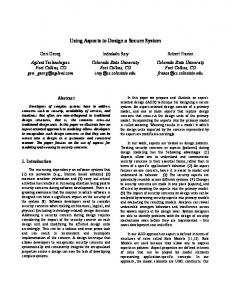
Security weakness of DCSK signal
A.
Figure
2
f3
(4)
plots the magnitude spectrum of the square of
the DCSK signal sample for
=
5. We can clearly detect
where
the odd multiple frequencies of the bit rate. The shape of the spectrum can be explained as follows. When the DCSK sample is squared, for a given bit, the reference slot and the data-bearing slot become identical. In this case, there are no frequency components at odd multiples of the bit rate because the contributions from the information-bearing slots will be cancelled by the contribution of the reference slots. This makes the DCSK system very weak in term of security.
Figure
2f3
1
Si
is random variable of the form:
hi,k abs(vI2K ai,k jbi,k), =
where
abs(.) ai,k, bi,k
+
(5)
+
is the absolute value for computing the mag
nitude, and
are two independent Gaussian random
variables with zero mean and variances equals to channel distribution depends on the value of
K.
1.
The
For low gain,
the channel can be seen as a Rayleigh channel, but when
K
is high the channel follows the Rice distribution.
III. TRANSMITTER STRUCTURE OF MC-DCSK
A.
first modulated into DCSK modulator where
chips are used to send each symbol. The transmitted DCSK
symbol is composed from the chaotic spreading code vector
Chip interleaving In contrast to chip mapping in time or in frequency, the
shows the general structure of the transmitter. The
data symbols
hi,k
chaotic chips can be interleaved in time and frequency in order to be transmitted on distant positions in an OFDM frame. To that end, an interleaving matrix can be visualized as,
965
In this matrix each row has one ' l' and the rest of the elements are zero and all the rows are independent. Since we
N X N,
have N sub-carriers, the size of this matrix is
where
each key (initial condition) generates a unique matrix to a unique combination. This matrix, when multiplied with the
Normaltud rrequ�lIcy
chips of the DeSK signal, interleaves the position of the chips, making it difficult to recover the data. For just
N
=
128, the 128!
complexity order needed for a potential eavesdropper is > 2128 ) which can be considered as good security level
(128!
today
Fig. 3. Magnitude of frequency components interleaved DCSK signal for a spreading factor f3 5 =
[12].
Since the chaotic generator is very sensitive to initial condi
IV. RECEIVER STRUCTURE AND BER PERFORMANCE
tions, this makes this property very useful for implementing an
ANALYSIS
algorithm to generate a new interleaving matrix from each new key (initial condition). In our paper, we use the chaos-based
[13].
interleaving algorithm explained in
Figure
4
shows the structure of the Me-DeSK receiver.
chip de-mapping
The transmitted interleaved OFDM symbol is:
( )-1,
After removing the guard interval, OFDM demodulation and is :
I
.
the input of the DeSK demodulator
(8)
(6) Thanks to an interleaving matrix
I,
the position of the chips
Remove Guard Interval & OF OM-I
are randomized. The interleaving is used first to increase the security, by breaking the similarity between the reference and the data samples of the DeSK signal. Secondly, this way, a diversity order corresponding to a spreading factor
N
=
Chip de·
2/3
can be achieved, provided the channel offers this degree of
[5]. ith received OFDM symbol Y
diversity The
is given by:
i,n
over
N
=
2/3 positions
Si,k kth Wi Wi [Wi,1, ... ,Wi,2,6j where
i
is
and
=
density
As shown in Figure
if the received signal
Zj
of the
ith
bit
the received symbols without any knowledge of the channel coefficients. The output of the correlator at the end of the
chip of the transmitted DeSK signal of the
are used to interleave the chaotic chips. Since the
chaotic map and the appropriate initial conditions are known at the receiver side, the matrix
I
The
ith
bit is decoded by comparing the output
Di
threshold equal to zero. By replacing the equations the decision variable
is reversible to deinterleave the
from the signal without knowing the initial values, the chaotic map and the inheritance matrix of the interleaving matrices. After the interleaving process, the frequency spectrum of the
3.
,6 Di 2:: Zi,kZi,(k+,6), k=1
(9)
=
transmitted chaotic chips, making it difficult to extract the data
square of the interleaved signal is plotted in Figure
ith
bit duration is given by:
with zero mean and power spectral
For each DeSK modulation data stream a certain number
I
4,
signal are correlated. In our system, the detector demodulates
is the Gaussian noise vector of the OFDM symbol
No / 2 .
of matrix
Block diagram of the general structure of the MC-DCSK receiver
passes by a delay circuit, then the two replicas of the received
(7)
bit
Fig. 4.
Di
(8)
to a
in
(9),
can be written as:
,6 Di 2:: (hi,kei,k + Wi,k)(hi,(k+,6)ei,(k+,6)+Wi,(k+,6)) (10) k=1 =
It can
be seen that spectrum is white, and no bit rate information can be retrieved. The interleaving process does not affect the orthogonality of the OFDM signals because the interleaving is performed before the inverse fast Fourier transform (IFFT).
966
(11)
In this expression, the first term is the useful signal, the other terms are zero mean random quantities. The ouptut of the correlator for DCSK of equation
(11)
can
be written in the form
f3 Di = Si L hi,khi,(k+f3)X;,k + A + B + C, k=l
(12)
where A, B, and C, are the three noise components of equation
(11)
Si
with zero means; then for a given
the decision variable for a given
ith
bit, the mean of
is derived as follows:
f3 E[Di] = SiE[L hi,khi,(k+f3)X;,kj, k=l Eb!) = kt=l hi,khi,(k+f3)X;,k
(13)
channel, the values of the variances can be found in
i,
and in
form is:
[14].
Bi
the mean of the decision variable can be
expressed by:
var [Xi,k]
20, K
and
=
var [hi,k]
and
(21) are equal.
Since the two noise components are uncorrelated, the general expression of the variance
Since the terms of (12) are uncorrelated and the noise
is:
samples and channel coefficients are independent (covariance
(22)
equal to zero), the conditional variance of the decision variable for a given bit
i
is:
In order to compute the BER with our approach, the error
var[Di] = E [(Eb� Si)2] + var [(Ai)] + var [(Bi)] + var [(Ci)] _(Ebe(i)s·)2. �
Eb!).
probability must first be evaluated for a given received energy Considering the bit energy (or chaotic chips) as a
deterministic variable, tanks to the central limit theorem, the
decision variable at the output of the correlator is random (15)
Gaussian variable. This error probability is therefore
P.e
(16) The variance of the component A is:
var [Ai] = var [t(hi,kXi,kSini,(k+f3))]] , k=l 2 var[Xi,kSini,(k+f3))]+ 1 [ EE [hi,k] [Xi,kSini,(k+f3)] 2 var [hi,k] + , var [Xi,kSini,(k+f3)] var [hi,k]
(17)
by
variance of
Ai'
is the complementary error function defined
=
Given the non-periodic nature of chaotic signals, the trans
[11].
In our case, the
bit energy and the channel gain vary, meaning that the overall
(18)
BER expression of the MC-DCSK system is given by:
+
E [Di] ) (E(i)) dE(i) (24) BER = 1 00 �2 erfc ( J2v be' be ar [Di] P
Finally, the variance is:
(20)
erfc(x) r fc(x e ) J; Jxoo e-J.t2 dp,
evitably varies from one bit to another
var [Ai] =/3 [ var [Xi,k] var [Wi,(k+f3)] � [hi,k]2 + var [hi'�JJ ' ) The equation
(23)
mitted bit energy after spreading by chaotic sequences in
The noise and the chaotic signal are zero mean:
var [Ai] =/3 �o [ var [Xi,k]E [h;,k] .
E [Dd ) , (Ebe(i)) = �erfc ( J2var 2 [Di]
where
The different samples of A are independent, leading to:
var [Ai] = /3
0 dB
is computed, and its general
We can see that the variances of
(14)
=
var[Bi] =/3 �O [ var [Xi,(k+f3)]E [h;,(k+f3)]' Ai Bi Ci
energy spread by chaotic sequence. For a given bit
[1]
Likewise, the variance of
as the received bit
Let us define
E�2 for f3
Fig. 5. Simulated distribution of bit energy and chaotic sequences generated with CPF map
o
(Eb� ) (i) . Ebe
where P energy
is the probability density function of the
In order to compute (24) we need to get the bit energy
(20)
gives the general expression of the
For a specific chaotic map and communication
distribution. First, we fitt the histogram of the energy distri bution for the chaotic sequences under study. Figure
0 dB.
the histogram of the bit energy of the CPF map for and
967
K=
5
/3
shows
=
20
.cc..cc..cc..cc.cc...cc.....cc"CC. "CC. ...."CC. . . ......"CC"CC. ...... . . .. . . ..cc..cc.:c, .cc. . ...•.•...... -'''''���;i;' . ���
and the DCSK system is to combine the advantages of both
' 10 r . . . . . . . . . . . . . . . . . . . . . . . . . . . . "CC . . . . . . ."CC . .r . . . . . . . . ."CC ..."' ..."' ..."' ..."' ..."' ...cc ...cc . . . . . . . . . . , . . . cccc cccccccc��=
.
.
.
..
. . . . . . . . ... .
.
..
. .
. . . . ... .
..
:
.
.. .
:.
..
. . . . . . . . . . . . . . . . . . . . . . . ..... . . . . .... .. . . . ..... . . . . . ... . . . . ..... . .
.. .
10
______ -
. . . . . . . . .
in a multipath propagation, and robustness to impulse noise. To increase the security of the proposed system, a spreading and interleaving in time and frequency are used to break the similarity between the reference and the data samples of
.
the DCSK signal. The results show that after chaotic chip interleaving, the spectrum of the MC-DCSK signal is white, and no bit rate information can be retrieved. The demodulation
_ - � . ::::::.:::::::::""_:.:.:.:� . .:.:. .\., �.:\. . :::. .:.:.:. ••• �:��;,:�� !��! :0iJ='�� iJ=' 40 H\ H :V \\ . HH.\\. \\ -
.r ----- c- am � R- �-ar-K-�-20-dB, iJ=' - u-te d B E -- -20 - p -.- - Si mu lation for K�20 dB , ��20
"
modulations, such as a high data rate, a simplified equalization
.
::
process is realized without knowing the channel coefficients. The performance of the MC-DCSK is evaluated under an m
r
-�
distributed fading communication channel. Without neglecting the dynamic properties of the chaotic signal, a new approach
mu lation for K�-20 dB , iJ='60 Si
is developed to compute the BER expression, taking into
IO·)O:------=--,:':--'--�,5 EblNO
account the non-periodic nature of the chaotic sequences and
[dB]
the channel gain
Fig, 6, Computed and Simulated BER for different number of spreading factor, and channel gain Kover m-distributed fading channel
REFERENCES
Since an analytical expression seems difficult to obtain, perform the BER computation. That is, the expression (24) can
International Workshop on Non-linear Dynamics of Electronic Systems,
Seville, Spain, 1996, pp, 92-97. [3] 1. Bingham, "Multicarrier modulation for data transmission: an idea whose time has come," Communications Magazine, IEEE, vol. 28, no. 5, pp. 5 -14, may 1990, [4] F. Lau, K. Cheong, and C. Tse, "Permutation-based DCSK and multiple access DCSK systems," Circuits and Systems I: Fundamental Theory and Applications, IEEE Transactions on, vol. 50, pp. 733-742, 2003. [5] S. Kaiser, "Multi-Carrier Cdma Mobile Radio Systems Analysis and Optimization of Detection, Decoding, and Channel Estimation," Ph.D. dissertation, VOl-Verlag, Fortschittberichte, Ph.D. dissertation, 1998. [6] S. Kondo and L. B. Milstein, "Multicarrier CDMA system with cochannel interference cancellation," in in Proc. VTC, Stockholm, Sweden, 1994. [7] S. Kondo and L. Milstein, "Multicarrier DS-CDMA systems in the presence of partial band interference," in Military Communications Conference, 1994. MILCOM '94. Conference Record, 1994 IEEE, oct 1994, pp. 588 -592 vol.2. [8] L.-L. Yang and L. Hanzo, "Performance of broadband multicarrier DS CDMA using space-time spreading-assisted transmit diversity," Wireless Communications, IEEE Transactions on, vol. 4, no. 3, pp. 885 - 894, may 2005. [9] M. Sushchik, L. S. Tsimring, and A. R. Volkovskii, "Performance analysis of correlation-based communication schemes utilizing chaos,"
be computed numerically, taking into account the bit-energy variation. The numerical integration expression is given by:
where
m
is the number of histogram classes and
P
(Ei�)
Ebe(i) .
is
d on
This approach can be applied for any type of chaotic sequence with quite simple operations: histogram of the bit energy followed by a numerical integration. In addition, this approach explores the dynamic properties of chaotic sequences and gives highly accurate results. V. SIMULATION Figure
6
Simulation results show the accuracy of
[1] F. C. M. Lau and C. K. Tse, Chaos-Based Digital Communication Systems. Springer-Verlag, 2003. [2] G. Kolumban, G. K. Vizvari, W. Schwarz, and A. Abel, "Differential chaos shift keying: a robust coding for chaos communication," in Proc.
the above proposed numerical integration method is used to
the probability of having the energy in intervals centere
K.
our approach.
Circuits and Systems I: Fundamental Theory and Applications, IEEE
shows the computed BER expression given in
equation (25), based on the bit energy distribution of the chaotic sequence, different channel gain values, the spreading factors and the Monte Carlo simulations of the secure MC DCSK system over an m-distributed fading channel. The results prove an excellent match between simulations and our computed BER expression. As shown in this paper, the system demodulates the received symbols without any knowledge of the channel coefficients. The performance of the system can be increased if a channel is estimated and then compensated on the receiver side.
Transactions on, vol. 47, pp. 1684-1691, 2000. [10] W. M. Tam, F. C. M. Lau, C. K. Tse, and A, 1. Lawrance, "Exact analytical bit error rate for multiple acces chaos-based communication systems," Circuits and Systems I: Fundamental Theory and Applications, IEEE Transactions on, vol. 9, pp. 473-481, 2004. [11] G. Kaddoum, P. Charge, D. Roviras, and D. Foumier-Prunaret, "A methodology for bit error rate prediction in chaos-based communication systems," Springer,Birkhiiuser, Circuits, Systems and Signal Processing, vol. 28, pp. 925-944, 2009. [12] M. Scott, Computing the Tate pairing, Topics in Cryptology. Springer Verlag, 2005. [13] L. Zhang, X. Xin, B. Liu, and Y. Wang, "Secure ofdm-pon based on chaos scrambling," Photonics Technology Letters, IEEE, vol. 23, no. 14, pp. 998 -1000, julyl5, 2011. [14] 1. G. Proakis, Digital communications. mcgraw, 2001.
VI. CONCLUSION In this paper, we have proposed a secure MC-DCSK com munications system. The goal behind using MC modulation
968