Design of a SiO2 top-cladding and compact polarization splitter-rotator based on a rib directional coupler Jing Wang,1,2 Ben Niu,2 Zhen Sheng,1 Aimin Wu,1 Xi Wang,1 Shichang Zou,1 Minghao Qi,2,* and Fuwan Gan1,3 1
State Key Laboratory of Functional Materials for Informatics, Shanghai Institute of Microsystem and Information Technology, Chinese Academy of Sciences, Shanghai 200050, China 2 School of Electrical and Computer Engineering and the Birck Nanotechnology Center, Purdue University, West Lafayette, Indiana 47907, USA 3
[email protected] *
[email protected]
Abstract: A compact polarization splitter-rotator based on a silicon-oninsulator rib asymmetrical directional coupler with SiO2 top-cladding is proposed. Unlike previously reported PSRs which specifically required the top-cladding material to be different from the bottom cladding in order to break the symmetry of the waveguide cross-section, our proposed PSR has no such limitation on the top-cladding due to the horizontal asymmetry of the rib waveguide. In addition, the device is highly compact and has a total length as short as 24 μm. Numerical simulation shows that a high conversion efficiency of ~97% is obtained at the wavelength of 1550 nm. With the width variation of ± 15 nm and the gap variation of ± 50 nm, the PSR still has high ER of 12 dB at the cross-port, showing large fabrication tolerance. This device can be cascaded to improve the performance at the through port and an example of a two-stage PSR is presented. The mode conversion between the strip waveguide and the rib waveguide is also discussed. ©2014 Optical Society of America OCIS codes: (130.3120) Integrated optics devices; (230.7370) Waveguides; (130.5440) Polarization-selective devices.
References and links 1.
W. Bogaerts, R. Baets, P. Dumon, V. Wiaux, S. Beckx, D. Taillaert, B. Luyssaert, J. Van Campenhout, P. Bienstman, and D. Van Thourhout, “Nanophotonic waveguides in silicon-on-insulator fabricated with CMOS technology,” J. Lightwave Technol. 23(1), 401–412 (2005). 2. C. Manolatou, S. G. Johnson, S. Fan, P. R. Villeneuve, H. A. Haus, and J. D. Joannopoulos, “High density integrated optics,” J. Lightwave Technol. 17(9), 1682–1692 (1999). 3. M. R. Watts, H. A. Haus, and E. P. Ippen, “Integrated mode-evolution-based polarization splitter,” Opt. Lett. 30(9), 967–969 (2005). 4. M. R. Watts and H. A. Haus, “Integrated mode-evolution-based polarization rotators,” Opt. Lett. 30(2), 138–140 (2005). 5. L. Liu, Y. Ding, K. Yvind, and J. M. Hvam, “Silicon-on-insulator polarization splitting and rotating device for polarization diversity circuits,” Opt. Express 19(13), 12646–12651 (2011). 6. Y. Ding, L. Liu, C. Peucheret, and H. Ou, “Fabrication tolerant polarization splitter and rotator based on a tapered directional coupler,” Opt. Express 20(18), 20021–20027 (2012). 7. Y. Ding, H. Ou, and C. Peucheret, “Wideband polarization splitter and rotator with large fabrication tolerance and simple fabrication process,” Opt. Lett. 38(8), 1227–1229 (2013). 8. D. Dai and J. E. Bowers, “Novel concept for ultracompact polarization splitter-rotator based on silicon nanowires,” Opt. Express 19(11), 10940–10949 (2011). 9. Y. Fei, L. Zhang, T. Cao, Y. Cao, and S. Chen, “Ultracompact polarization splitter-rotator based on an asymmetric directional coupler,” Appl. Opt. 51(34), 8257–8261 (2012). 10. J. Wang, C. Qiu, H. Li, W. Ling, L. Li, A. Pang, Z. Sheng, A. Wu, X. Wang, S. Zou, and F. Gan, “Optimization and demonstration of a large-bandwidth carrier-depletion silicon optical modulator,” J. Lightwave Technol. 31(24), 4119–4125 (2013).
#203178 - $15.00 USD (C) 2014 OSA
Received 16 Dec 2013; revised 7 Feb 2014; accepted 8 Feb 2014; published 14 Feb 2014 24 February 2014 | Vol. 22, No. 4 | DOI:10.1364/OE.22.004137 | OPTICS EXPRESS 4137
11. D. Dai, Y. Tang, and J. E. Bowers, “Mode conversion in tapered submicron silicon ridge optical waveguides,” Opt. Express 20(12), 13425–13439 (2012).
1. Introduction Silicon-on-insulator (SOI) has been widely employed in integrated photonic devices for its high-refractive index contrast in waveguide structures as well as compatibility to mature CMOS-compatible fabrication processes [1]. However, strong birefringence exists in SOI waveguides, which makes the performance of these SOI-based photonic devices highly polarization-sensitive [2]. To overcome this drawback, several approaches have been proposed to manipulate polarizations on chip, such as using a polarization beam splitter (PBS) [3] to split the input light of different polarizations into different outputs, or using a polarization rotator (PR) [4] to rotate the polarization by 90°. Another promising and efficient polarization-handling approach is to use a polarization splitter-rotator (PSR) [5–9], which works similarly to a cascade of a PBS and a PR, to complete the functionality of polarization splitting and mode conversion in only one device. Several PSRs have been reported based on various structures, one of them being an asymmetrical directional coupler (DC) that consists of two waveguides with broken symmetry in the waveguide cross-section. As a result, mode conversion occurs for two orthogonal modes when they have the same effective index, satisfying the phase-matching condition. Recently, compact, fabrication-tolerant and broadband DC-based PSRs have been reported [5–9]. However, these PSRs require an air top-cladding to break the symmetry in the waveguide cross-section, limiting their ability to integrate with other silicon-based devices (e.g., a silicon modulator which has a SiO2 top-cladding between the electrodes and the optical waveguide [10]) to form large-scale polarization-diversity circuits. Moreover, these device may not be stable (e.g., getting oxidized, absorbing moistures, etc.) due to lack of the protection of the top-cladding. Furthermore, these PSRs have large footprint because of the relatively weak coupling between the waveguides in the DC. In [6, 7], the authors demonstrated two fabrication-tolerant SOI PSRs. However, these devices have lengths of >100 μm. In [8], a novel PSR design with two-step mode conversion is proposed, which requires an additional length to complete the mode conversion from the TM0 mode to the TE1 mode. And the design process is more complicated. A compact PSR which consists of a slot waveguide and a strip waveguide is presented in [9]. However, the slot waveguide has a small gap of 50 nm, making the fabrication relatively difficult. In this work, we propose a novel PSR design based on a rib directional coupler with SiO2 top cladding, which has intrinsic horizontal asymmetry in its waveguide cross-section. Therefore, the device shows higher stability than the devices without top-cladding and thus increases its potential in the applications of polarization diversity circuits. Meanwhile, the coupling between the rib waveguides is stronger than that between the strip waveguides. As a result, the device length is only ~24 μm when the gap between the waveguides in the DC is 0.15 μm. Further analysis of the PSR is discussed in terms of fabrication tolerance, improving the performance at the through-port and mode conversion between the strip waveguide and the rib waveguide. 2. Device design Figure 1(a) shows the schematic of the proposed PSR, which consists of two SOI rib waveguides with different widths. The device has upper and lower cladding of SiO2. The gap (G) between the two waveguides remains the same in the straight DC region and gradually increases in the region of an S-bend connecting the cross-port and the DC. The operation principle of the rib-DC-based PSR is similar to that of the PSR devices based on a strip DC. In order to enable efficient coupling between two orthogonal modes (TE0, TM0), phasematching condition is required. In other words, the effective index of the TM0 mode in the input waveguide is equal to that of the TE0 mode in the adjacent waveguide. Thus, if the coupling length (Lc) is optimized, the input TM0 mode can be converted into the TE0 mode in
#203178 - $15.00 USD (C) 2014 OSA
Received 16 Dec 2013; revised 7 Feb 2014; accepted 8 Feb 2014; published 14 Feb 2014 24 February 2014 | Vol. 22, No. 4 | DOI:10.1364/OE.22.004137 | OPTICS EXPRESS 4138
the adjacent waveguide, while the input TE0 mode keeps propagating along the input waveguide.
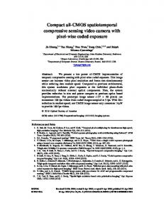
Fig. 1. (a) Schematic of the proposed PSR based on a rib DC. The cross-section of the DC is also presented. (b) Effective indices of the first three modes in a rib waveguide as a function of the waveguide width. Inset: relationship between W1 and W2 when the phase-matching condition is satisfied.
In order to find the optimum widths (W1, W2) of the two waveguides that satisfy the phase-matching condition, we used a commercial simulation package (FIMMWAVE) to calculate the effective indices of the first three modes in an SOI rib waveguide, which has a waveguide height (H) of 250 nm and a slab height (Hslab) of 50 nm. The refractive indices of silicon and SiO2 are nSi = 3.455 and nSiO2 = 1.445 at 1550 nm, respectively. The simulated result as a function of the rib waveguide width is shown in Fig. 1(b). We choose W1 = 262 nm and W2 = 500 nm such that the effective index of the TM0 mode in the wide waveguide equals that of the TE0 mode in the narrow waveguide. Consequently, there will be efficient mode conversion between them. In contrast, the TE0 mode in the wide waveguide is hardly affected by the narrow waveguide because its effective index is different from that of any guided modes in the narrow waveguide. Therefore, for the TE0 mode, the phase-matching condition is unsatisfied and the TE0 mode only propagates along the input waveguide. We also extracted the widths (W1, W2) of the two waveguides when the phase-matching condition is satisfied for the input TM0 mode. As shown in the inset of Fig. 1(b), the width W1 increases almost linearly with increasing W2 and the slope of the curve is ~1/3. This implies that the phase-matching condition is more sensitive to the variation of W1 due to fabrication errors of the narrow waveguide than of the wide one. Nevertheless, our PSR exhibits larger fabrication-tolerance than the similar PSR based on a strip DC with air topcladding [5], because the corresponding curve of the latter has a very small slope of ~1/12. In other words, for the PSR with air-cladding, 1 nm width variation of the narrow waveguide requires about 12 nm adjustment of the width of the wide waveguide in order to satisfy the phase-matching condition, making this PSR with air-top-cladding much more sensitive to fabrication errors than ours. A three-dimensional simulation software package (FIMMPROP) was used to further analyze the mode propagation and conversion in the PSR. In this simulation, the gap (G) between the two waveguides is 150 nm in the straight DC region and gradually increases to Gout ( = 1 μm) at the output ports. The length (Ls) of the S-bend is 15 μm. Figures 2(a) and 2(b) show the simulated conversion efficiency as a function of coupling length (Lc) at the cross-port and the through-port, respectively. We note that the conversion efficiency from the TM0 mode to the TE0 mode has a maximum of ~97% at the cross-port when Lc = 9 μm. And
#203178 - $15.00 USD (C) 2014 OSA
Received 16 Dec 2013; revised 7 Feb 2014; accepted 8 Feb 2014; published 14 Feb 2014 24 February 2014 | Vol. 22, No. 4 | DOI:10.1364/OE.22.004137 | OPTICS EXPRESS 4139
the extinction ratio (ER) is 20 dB and 26.7 dB at the cross-port and the through-port, respectively. Moreover, the ER at the cross-port is less sensitive to the variation of the coupling length because the narrow waveguide cannot allow the TM0 mode transmission and filters the TM0 mode converted from the input TM0 mode. The dependence of the conversion efficiency on the wavelength is shown in Figs. 2(c) and 2(d). For the cross-port, the ER is better than 19 dB in a 100 nm wavelength range from 1500 nm to 1600 nm. However, because the effective index is wavelength-dependent, when the operating wavelength changes, the phase-matching condition is no longer satisfied and the mode conversion from the TM0 mode to the TE0 mode becomes less efficient. As a result, the unconverted TM0 mode will propagate through the input waveguide and thus the ER is degraded at the throughport.
Fig. 2. Conversion efficiency as a function of (a-b) coupling length (Lc) and (c-d) wavelength. The conversion efficiency below −35 dB is not shown.
Figure 3 shows the mode propagation in the PSR for different input modes. It can be seen that the TM0 mode in the input waveguide is predominantly converted into the TE0 mode at the cross-port, while the input TE0 mode only propagates along the input waveguide with little coupling with the adjacent waveguide.
Fig. 3. Mode propagation when the input is (a) the TM0 mode and (b) the TE0 mode. The wavelength is 1550 nm. The PSR has design parameters as follows: W1 = 262 nm, W2 = 500 nm, G = 150 nm, Gout = 1 μm, Lc = 9 μm, Ls = 15μm.
#203178 - $15.00 USD (C) 2014 OSA
Received 16 Dec 2013; revised 7 Feb 2014; accepted 8 Feb 2014; published 14 Feb 2014 24 February 2014 | Vol. 22, No. 4 | DOI:10.1364/OE.22.004137 | OPTICS EXPRESS 4140
3. Discussion Further analysis of the conversion efficiency as a function of the gap variation (ΔG) and the width variation (ΔW1) is presented in Figs. 4(a)–4(d) for the operating wavelength of 1550 nm. Because the phase-matching condition is more sensitive to the width variation of the narrow waveguide, here we assume W2 remains the same. It can be seen that the ER at the cross-port is relatively less sensitive to the variations of both G and W1. A high ER of >12 dB is obtained for the gap variation (ΔG) of ± 50 nm and the width variation (ΔW1) of ± 15 nm, showing large fabrication tolerance. However, under the same conditions the performance at the through port is degraded substantially. Nevertheless, the ER is still better than 10 dB for a gap variation of ± 50 nm. We also study the performance variation affected by the etch depth as shown in Figs. 4(e) and 4(f). The performance is affected considerably by the etch depth variation, but an acceptable performance can be still achieved in the depth range from 55 nm to 50 nm. Another fabrication imperfection occurs during the uppercladding oxide deposition, which might lead to nontrivial refractive index variation of the upper-cladding. Figs. 4(g) and 4(h) show the simulated results and it can be seen that