from S81 to S82, in which it sends an integer value from variable tp to the channel. Both transitions are triggered by CS signal on. We use the CSP [14] notation ...
> REPLACE THIS LINE WITH YOUR PAPER IDENTIFICATION NUMBER (DOUBLE-CLICK HERE TO EDIT)
REPLACE THIS LINE WITH YOUR PAPER IDENTIFICATION NUMBER (DOUBLE-CLICK HERE TO EDIT) < communications and computations are assumed to be instantaneous. The SR model of computation has been used a semantic base for several languages. Some of them, such as Esterel [9] and Argos [10], are suitable for specifying controldominated systems. Others, such as Lustre [11] and Signal [12] have a dataflow flavor. The use of synchronous languages has been successfully demonstrated in many practical embedded systems. However, a pure synchronous specification of a large scale heterogeneous distributed system with many processes could result in excessive synchronizations leading to inefficient implementations. Ptolemy [13] targets complex embedded systems by hierarchically combining several models of computation. Although it has code generation capabilities, it is still primarily used as a simulation environment. Process algebras such as CSP [14] and CCS [15] have been useful for analyzing interaction among different models of computation, but they are too abstract to be used for practical specification of large scale distributed heterogeneous systems. In this paper, we present Distributed DFCharts (DDFCharts), a model of computation with a complete set of features necessary for design of distributed heterogeneous systems including support for control-dominated behaviour, data-dominated behaviour, distributed processes, efficient implementation and verification. DDFCharts has been created by unifying two related models, DFCharts and McCharts. DFCharts [16], [17] addresses heterogeneity in embedded systems by combining synchronously communicating finite state machines with synchronous dataflow graphs (SDFG) [5], but it does not provide mechanisms for modeling distributed systems. McCharts [18] is suitable for design of distributed control dominated systems, but it does not provide any special support for digital signal processing parts. We will use a practical example to demonstrate how DDFCharts can be used for specification of distributed heterogeneous systems. We will also describe a design flow, which enables implementation of DDFCharts specifications on heterogeneous multiprocessor architectures. Previous papers on DFCharts and McCharts contained little material on implementation. Thus, besides the integration of McCharts and DFCharts, the multiprocessor implementation of DDFCharts is also a major contribution of this paper. The rest of the paper is structured as follows. Section 2 introduces the main concepts for modeling in DDFCharts. Section 3 describes the DDFCharts approach in more detail using a practical example. Section 4 presents some important details of the formal semantics of DDFCharts, which is based around multiclock finite state machines (MCFSM), initially introduced in [18]. Section 5 and 6 cover the implementation of DDFCharts by describing allocation, partitioning and synthesis from specifications. Section 7 presents implementation results for an example presented in section 3. Section 8 discusses related work by making direct comparisons between DDFCharts and other approaches. Finally, section 9 concludes the paper.
2
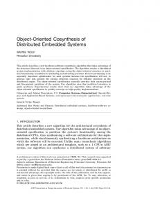
II. INTRODUCTION TO DDFCHARTS In DDFCharts, finite state machines (FSM) and synchronous dataflow graphs (SDFG) [5] are combined using five operators: symmetric asynchronous parallel (SAP), asymmetric asynchronous parallel (AAP), synchronous parallel (SP), refinement (R) and hiding (H). In section 4, where the formal semantics is discussed, the operators will also be labeled as //, \\, ||, ↓, \ respectively. Figure 1 gives the first illustration of a specification in DDFCharts. The specification for simplicity does not contain all details of signal labels. Full semantics will be discussed in the next section with real-world examples. At the top level, a DDFCharts specification represents a network of nodes, which contain compositions of FSMs and SDFGs. FSMs from different nodes are connected using the SAP operator. The other operators are used inside a node. Inside a node, FSMs may be driven by different clocks.
SAP
N2
N1
N3 SP
FSM1 (gclk)
AAP
FSM2 (gclk)
SDF1
R FSM3 (gclk)
AAP FSM4 (clk1)
Figure 1. Hierarchy and operators in DDFCharts A clock represents a sequence of reactions in a similar way as in synchronous languages. At the specification level, each tick is assumed to be instantaneous. When the system is implemented each tick has a finite duration. Since DDFCharts specifications are primarily intended for software implementation on multiprocessor architectures, DDFCharts clocks should not be thought of as hardware clocks. Thus, clock ticks are not necessarily equal in duration at the implementation level. Each node has a special clock called master clock or global clock (gclk). FSMs that are driven by the same clock can be connected with the SP operator. They execute in lockstep and may communicate via local signals that are handled using the hiding operator in a similar way as in Argos [10]. A state of an FSM can be refined using the refinement (R) operator. If the refined FSM is driven by the master clock the refining FSM
> REPLACE THIS LINE WITH YOUR PAPER IDENTIFICATION NUMBER (DOUBLE-CLICK HERE TO EDIT) < can be driven by any clock. However, if the refined FSM is not driven by the master clock, the refining FSM must be driven by the same clock. For example, FSM4 could only be refined by an FSM driven by clk1. An FSM that is driven by the master clock can be connected with an FSM driven by another clock using the AAP operator. In that case communication is performed through rendezvous channels in a way that resembles communication in process algebra, in particular CCS [15]. The same type of communication is applied with the SAP operator. An FSM driven by the master clock can also be connected with an SDFG using the AAP operator. Unlike a globally asynchronous locally synchronous (GALS) node, a DDFCharts node is not synchronous in general since it can contain multiple unrelated clocks driving FSMs. In addition, SDFGs operate at their own speeds and their execution can be modeled by separate logical clocks as will be discussed in section 4. A clock domain is a set of FSMs that are driven by the same clock. The distinguished clock domain is represented by master clock. Master clock driven FSMs can activate and terminate other clock domains, hence the name master or global clock. These “slave” clock domains can be used to model unrelated tasks that are often dataintensive and time-consuming. Thus, slave clock domains are usually slower than the master clock domain. This situation can be found in many large embedded systems. For example, in a mobile phone, channel coding and a video game are examples of processes that can be modeled as slave clock domains in DDFCharts. The master clock domain would control these processes, but it would also handle user interface, network protocols and other activities where control logic with quick reactions is important. III. MODELING IN DDFCHARTS We will describe modeling in DDFCharts using the system called frequency relay as an example. Power systems need protection from overloading. When a power system is overloaded some loads must be disconnected in order to prevent damage. A significant decrease in the frequency level of the main AC signals whose normal value is 50 (or 60) Hz indicates that the system may be dangerously overloaded. The same problem is also detected when the rate of change of the AC signal is too fast. The frequency relay is a sensor that measures the frequency and its rate of change in a power network. Measurement results are compared against a set of thresholds that can be modified during the system operation. If the current thresholds indicate that the frequency is too low or its rate of change too fast some loads are disconnected from the network by opening one or more switches as determined by a decision algorithm. The decision algorithm also uses a timing parameter that is received through a CDMA link. It should be noted that the frequency relay case study was also used in [17], but here it is extended with the CDMA link. While increasing the complexity of the system, this change has also made the system distributed. Hence, DDFCharts becomes a suitable
3
formalism. The general form of an FSM transition in DDFCharts is t[c]/O,P. t is the transition trigger which represents a Boolean expression on signals; c is the condition on variables; O is the set of emitted output signals; P is the set of invoked procedures. Procedures are sequential and are written in an imperative language. It is important to emphasize that procedures must be executed in a finite amount of time because the duration of each tick has to be bounded when the system is implemented. Thus, infinite loops inside procedures are not allowed. Local variables can be defined inside procedures, but they cannot retain values between procedure calls. Thus, all results have to be written to variables that are defined inside FSMs Figure 2 shows the top level, which consists of two nodes. All FSMs in N1 are driven by the master clock gclk1 while all FSMs in N2 are driven by the master clock gclk2. The main operation of the system is contained inside N1 (Figure 3). N2 is used to receive the timing parameter using a CDMA link, which is passed through channel on to N1 where it is stored in variable tp (timing parameter). The operation of SAP operator can be explained using the FSMs at the top level. FSM1 from node N1 and FSM8 (Figure 4) from node N2 are connected with the SAP operator. They communicate through channel on. A channel status signal (CS signal) is associated with every rendezvous channel. When communication is happening on a rendezvous channel, the corresponding CS signal is true. Otherwise, it is false. A CS signal can trigger a transition in an FSM just like any other signal. Communication on a rendezvous channel occurs when both sides are ready. It is instantaneous. This is exactly the reason why a CS signal can be easily associated with communication through a rendezvous channel. If communication through a rendezvous channel was not atomic i.e. it takes multiple clock ticks instead of a single clock tick, it would be more difficult to define how channel communication can trigger transitions in FSMs. An FSM is ready to communicate through a channel when it enters the rendezvous state corresponding to the channel. Only one channel can be associated with a rendezvous state. A rendezvous state must have an outgoing transition that is triggered by the corresponding CS signal. In this example, the rendezvous states for channel on are S11 in FSM1 and S81 in FSM8. When a rendezvous occurs on channel on, FSM1 makes the transition from S11 to S12. In this transition, it receives an integer value from the channel and stores it into variable tp, and completes procedure init_thresh(), in which thresholds (thr1 to thr6) are initialized. On the other side of the channel, FSM8 makes the transition from S81 to S82, in which it sends an integer value from variable tp to the channel. Both transitions are triggered by CS signal on. We use the CSP [14] notation where “!” denotes output while “?” denotes input. When a rendezvous on channel on happens, gclk1 and gclk2 are synchronized i.e. their ticks
> REPLACE THIS LINE WITH YOUR PAPER IDENTIFICATION NUMBER (DOUBLE-CLICK HERE TO EDIT)
REPLACE THIS LINE WITH YOUR PAPER IDENTIFICATION NUMBER (DOUBLE-CLICK HERE TO EDIT) < variable.
1
ch1
FSM4 (gclk1)
variable: float ave_freq=0; int fs=0, rs=0; start_roc/ aroc_calc( )
S41
S42
true/rd
true/ rs_calc( )
S43
S31
[din ==0] S32
rd
[din !=0] /af_calc( ) S33
true/ fs_calc( ),start_roc signal: start_roc, rd;
Figure 6: Frequency and rate of change calculations Given the information from fpout, FSM3 calculates the frequency, while FSM4 (Figure 6) calculates the rate of change. FSM3 and FSM4 also compare the frequency and rate of change against the thresholds (defined in Figure 3) and store the result in variables fs and rs (frequency status and rate of change status). FSM3 and FSM4 are connected by the SP operator. Thus, they must have the same clock, which is in this case gclk1. FSMs that are connected by the SP operator can communicate with local signals and shared variables. The only local signal used by FSM3 and FSM4 is start_roc (start rate of change calculation). When FSM3 takes the transition from S33 to S34 it emits start_roc. In the same clock tick, start_roc triggers the transition from S41 to S42 in FSM4. The variable that is shared between FSM3 and FSM4 is ave_freq (average frequency). FSM3 is the writer while FSM4 is the reader. FSM3 writes ave_freq in procedure af_calc(). Among concurrently running FSMs only one FSM is allowed to write a shared variable. The new value becomes available to the readers in the next tick. On the other hand, local variables that are used by single FSMs can be written multiple times in procedures within the same tick. When a local variable is written, the new value takes effect immediately, instead of waiting for the next tick to occur as in the case of shared variables. FSM9 (gclk2)
FSM10 (clk2)
S91
S101 ch2!
ch1?tp/ update
ch2?
S93
Figure 7: FSM9 and FSM10
tp_res 1
192
remove repeated symbols
384
block deinterleaver
384
384
rin
80
fpout?din
S34
SDF2 - receiver
convert to integer 80
FSM3 (gclk1)
5
tp_ena
2
S102
CRC decoder
88
88
remove 8-bit encoder tail
96
96
convolutional decoder
192
Figure 8. Decoding in CDMA receiver N2 consists of three FSMs and one SDFGs. The top level FSM is shown in Figure 4. In state S81, FSM8 sends the current value of tp to N1 and then goes to S82 where it obtains a new value for tp. S82 is refined by two FSMs and one SDFG as shown in Figure 4. FSM9 (Figure 7) is driven by the master clock of node N2. It receives the value of the timing parameter from SDF2 which represents a CDMA receiver. Beforehand, it has to complete a rendezvous with FSM10 (Figure 7) that is driven by clk2. FSM10 represents a simple user interface, which enables the reception of the timing parameter. The rendezvous between two FSMs connected by the AAP operator is the same as that of the SAP operator. Both FSMs must be in rendezvous states for the rendezvous to happen. In this case, the rendezvous states are S91 for FSM9 and S102 for FSM10. Figure 7 shows that state S102 can be left before the rendezvous occurs if signals tp_res (transition parameter reset) is present. However, if both transitions are enabled in the same clock tick, the rendezvous transition (ch2!) has priority, as indicated by the priority labels. Transition priorities can be freely assigned in DDFCharts except in rendezvous states, where the rendezvous transition always must have the highest priority. After FSM9 has completed the rendezvous with FSM10, it has to complete another rendezvous with SDF2 to receive the value of tp, which will then be used by FSM8. The receiver (SDF2) decodes an incoming packet of 384 bits to produce a message of 80 information bits, which are then converted into a single integer value. Note that this is only a partial model for the receiver since demodulation and RF stages are not shown. FSM8, which is driven by the master clock, could further be refined by both FSMs that are driven by gclk2 and those that are driven by other clocks. On the other hand, FSM10 can only be refined by FSMs that use its clock i.e. clk2. With this refinement rule, all clocks could easily be related to the master clock, so that the whole node can be made synchronous if this is beneficial for design steps after specification. Different clocks in DDFCharts specifications are unrelated initially. However, it is possible for the designer to enforce a relation between a master and slave clock in order to reduce verification effort. This issue will be discussed in detail in section 6. For example, it can be specified that every tick of clock clk2 takes four ticks of gclk2 in Figure 7 using the label FSM10(clk2=4*gclk2) . This is also possible with SDFG iterations. For example, it can be specified that every iteration of SDF1 takes five ticks of gclk1 using the label SDF1(5*gclk1). Allowing such property does not change the semantics of DDFCharts operators presented in this section. It
> REPLACE THIS LINE WITH YOUR PAPER IDENTIFICATION NUMBER (DOUBLE-CLICK HERE TO EDIT) < only reduces the set of possible behaviors. Communication between related clocks would still be performed from rendezvous states, but in this case it becomes predictable when it will take place.
states, CS signals are only tested in rendezvous states. O is the set of output signals. V is the set of variables. C is the set of conditions on variables. Like input signals, CS signals and b
a
IV. FORMAL SEMANTICS The formal semantics of DDFCharts represents an extension of the McCharts semantics, which was presented in [18] and draws from synchronous language Argos [10]. In Argos, two or more FSMs are combined by the operators to produce an equivalent FSM. The same is done by McCharts operators, but instead of single clock FSMs, multiclock FSMs (MCFSM) are used. DDFCharts uses the same set of operators as McCharts, SAP (//), AAP (\\), SP (||), refinement (↓), and hiding (\). However, it extends that model with the use of variables and its AAP operator works with SDFGs. Therefore, the main purpose of this section is to demonstrate MCFSM with variables and how SDFGs are incorporated into the MCFSMbased operators. We present a simple multiclock FSM in Figure 9 before the formal definition. In a multiclock FSM, transitions can be driven by different clocks. The FSM in Figure 9 has two clocks, k, which is its master clock, and k1. At the beginning of each transition label, it is indicated which clock drives it. Synchronization of clocks is indicated by using brackets in the clock label. Inputs are tied to specific clocks. At each tick of k, input a is read. On the other hand, input b is tied to clock k1. In states S1, S2 and S3, where k and k1 are not synchronized, their transitions are simply interleaved. a and b are read separately. Depending on implementation, ticks of asynchronous clocks may happen to coincide. In states S1,S2 and S3, if ticks of clocks k and k1 happen to occur at the same time and their transitions are enabled simultaneously, the outgoing transition is selected randomly. In state S4, where k and k1 are synchronized, a and b are read at the same time. Clock synchronization is denoted as . In this notation, the clock outside the parentheses has to be a master clock. Other clocks are placed in the parenthesis. In each state there is a transition for every possible input combination. A dot between inputs means logical AND while a bar over an input means NOT. Definition 1: MCFSM with variables A = (CLK , Q, q 0 , I , R, O, V , C , T , RQ, Proc) CLK is the set of clocks that drive MCFSM transitions. Q is set of states where q0 is the initial state. I is the set of input signals. Each input signal can either be present (true) or absent (false). R is the set of channel status signals (CS signals). In DDFCharts semantics, CS signals are tested in the same way as input signals. When a clock tick occurs, a CS signal is true if a rendezvous is happening on the corresponding channel and false otherwise. However, while input signals are tested in all
6
a
a
b a
a.b/o
S2
S1
a
a.b
a.b/o
a.b
b b
S4
b S3 b a
Figure 9. A multiclock FSM output signals, conditions are Boolean; they can be true or false. T is the set of transitions. RQ is the rendezvous mapping function, which maps channels to states. Proc is the set of procedures on variables. Definition 2: MCFSM transitions T ⊆ CLK × 2 CLK × Q × B( I ′) × B(C ′) × B( R ′) × 2 O × Proc × Q A transition is driven by a clock clk taken from the set CLK. In addition, there could be a set of clocks taken from 2CLK (power set of CLK) that have to synchronize with clk when the transition occurs. B(I ′) where I ′ ⊆ I is the set of Boolean formulas on input signals that are bound to clk and clocks synchronized with it. Each formula is a complete monomial, or in other words a conjunction that has to contain every input signal in I ′ . B(C ′) ,where C ′ ⊆ C , is the set of Boolean formulas on variable conditions that are bound to clk and clocks synchronized with it. Each formula is a complete monomial. B(R ′) where R ′ ⊆ R is the set of Boolean formulas (again complete monomials) on CS signals that are linked to the source state of the transition and bound to clk and clocks synchronized with it. We can write a transition as a tuple (clk , q, i, o, p, q ′) .
i = m.c.r where m, c and r are monomials over input signals, conditions on variables and CS signals respectively. The dot between monomials denotes the AND operation exactly in the same way as inside monomials. o and p denote output signals and procedures. Variables in DDFCharts are unbounded i.e. each variable can take an infinite range of values. If each value was represented explicitly, any formal analysis would be difficult. Hence, it is necessary to abstract data in some way. In DDFCharts, this is done by representing each condition on variable as a signal. It only matters whether it is true or false.
> REPLACE THIS LINE WITH YOUR PAPER IDENTIFICATION NUMBER (DOUBLE-CLICK HERE TO EDIT) < A similar approach for data abstraction is used in Esterel Studio [9] and Polis [20]. Data abstraction is illustrated in Figure 10 where the specification (Figure 10 (a)) has one input signal and two conditions on variables. In Figure 10 (b), b and c stand for conditions [v>4] and [v REPLACE THIS LINE WITH YOUR PAPER IDENTIFICATION NUMBER (DOUBLE-CLICK HERE TO EDIT) < DDFCharts approach aims to support a wide range of applications. VII. FREQUENCY RELAY RESULTS To illustrate implementation of DDFCharts specifications we present results for node N1 from the frequency relay example. The implementation architecture consisting of a ReMIC/Nios II pair is shown in Figure 16. It was implemented on EP1S60F1020C5, an FPGA from the Altera Stratix family. The number of logic elements (LE) consumed by the architecture is 2677. The program memory for Nios II requires around 25KB while the program memory for ReMIC requires around 4KB. The frequency of the Nios II clock is 110 MHz. ReMIC has a slower clock running at 61 MHz. The execution time of ST iterations running on the Nios II processor is just below 90 µsec and it has very small variation. This is not surprising considering that the ST code has very little branching logic. The execution on the ReMIC processor is quite different. The time taken to execute a tick of the master clock varies widely depending on the current states and the destination states of the seven FSMs in N1. Table 1 shows some examples of state transitions and execution times for four possible ticks (n, m, p q) for seven FSMs. The last column shows the worst case execution time in terms of ReMIC clock cycles. The longest tick in the system is given in row 2 (Tick m). In this tick, FSM7 is inactive (denoted by x) while FSM1, FSM2, FSM3, FSM4, FSM5 and FSM6 take the transitions from states S11, S23, S33, S41, S51 and S61 to states S12, S21, S34, S42, S51 and S61, respectively. By multiplying 1302 with the ReMIC clock period we find the real time taken is 21.3 µsec.
Remic1
SDF_start
off reset n1 n2 n3 inth cancel done skip thresh0 thresh1
channel on (data and rendezvous flags)
FSM scheduler FT1, FT2, FT3, FT4, FT5, FT6, FT7 tick handler
SDF_stop Rendezvous_ready Rendezvous_done Nios1 ST1 SDF scheduler
SM
sample (AC waveform)
Figure 16: Architecture for node N1 in frequency relay The relative speed of SDF1 does not have a significant impact on the behavior of node N1. Thus, the option of forcing each iteration of SDF1 to take certain number of gclk1 ticks was not selected in the final implementation. However, it is still important to consider performance implications that would arise if this option was selected. When controlling the length
11
of SDF iterations, the most important question is how many ticks of the master clock should each iteration take. The only valid approach in finding the answer is to work with the longest tick in the system. What has to be found out is how many of those ticks fit within the time taken by each SDFG iteration. It was mentioned earlier that Nios II completes each SDFG iteration in slightly less than 90 µsec. However, it cannot start the next iteration until a new sample arrives, which happens every 125 µsec (since the sampling frequency is 8 KHz). Thus each iteration effectively takes 125 µsec. Obviously, the longest tick has to be stretched from 21.3 to 25 µsec so that each iteration consumes five ticks. This is an increase of nearly 20%. It is not difficult to imagine that the adjustment could be greater if there were multiple SDFGs in the node. Moreover, event-driven execution is no longer possible. ReMIC now has to read inputs periodically every 25 µsec. This may not be the preferred option, considering that its inputs arrive asynchronously from the environment. VIII.
RELATED WORK
DDFCharts overlaps to some extent with Ptolemy, synchronous languages, globally asynchronous locally synchronous (GALS) languages and process algebras. While these models of computation and languages have been used successfully for certain types of embedded systems, they lack a complete set of features necessary for design of distributed heterogeneous systems. DDFCharts aims to fill this gap. In the following paragraphs we will discuss each group of models mentioned above and compare it against DDFCharts. With the presence of SDF graphs, DDFCharts resembles Ptolemy [13], where SDF is the most developed domain. In particular, DDFCharts is similar to a subset of Ptolemy called *charts [26], which combines finite state machines with a few other models of computation. Ptolemy has a wider scope than DDFCharts since it includes models of computation that are suitable for modeling analog systems. In terms of modeling, the biggest difference is that Ptolemy combines models of computation only hierarchically while DDFCharts also allows parallel compositions. In Ptolemy models, at each hierarchical level blocks have to obey the semantics of a single model of computation, but internally each block can be refined into a system that behaves according to some other model. The advantage of purely hierarchical heterogeneity is a strong emphasis on modularity. On the other hand, it may be difficult to devise a meaningful communication mechanism between the outer and inner models, which could make specification more difficult and reduce implementation options. While Ptolemy has some code generation capabilities, a complete design flow which maps heterogeneous specifications onto a multiprocessor architecture has still not been developed. The inner model may lose some properties while adjusting to the outer model. This issue becomes apparent when the frequency relay is specified in Ptolemy. Figure 17 shows a possible solution for N1. The top level MoC is FSM. State S2 is refined by a network of blocks that follow the semantics of the synchronous reactive (SR) model. All blocks are internally
> REPLACE THIS LINE WITH YOUR PAPER IDENTIFICATION NUMBER (DOUBLE-CLICK HERE TO EDIT)
REPLACE THIS LINE WITH YOUR PAPER IDENTIFICATION NUMBER (DOUBLE-CLICK HERE TO EDIT) < of control-dominated systems resulted in significantly better performance than purely synchronous ones. A strong advantage of purely synchronous specifications is a large reduction of verification effort due to the absence of interleaving among concurrent processes. The DDFCharts model of computation allows every SDFG to operate at its own speed in order to support implementation efficiency. However, it also possible to relate the iteration time of a SDFG to a master clock when verification effort needs to be reduced. This flexibility in DDFCharts design flow makes it possible to address both implementation and verification issues effectively. The globally asynchronous locally synchronous (GALS) model of computation is highly suitable for design of distributed systems due to its composition. The top level consists of a set of nodes that are asynchronously composed, but the processes inside each node must be synchronous. Several GALS languages with formal semantics have been proposed including Multiclock Esterel [9], Polis [20], Communicating Reactive Processes (CRP) [29], Communicating Reactive State Machines (CRSM) [30] and SystemJ [31]. Most of these languages have adopted various constructs from Esterel to support control-dominated behaviour. DDFCharts is more general than GALS since asynchronous compositions are not restricted to the top level of hierarchy. This, however, is not the principal difference between DDFCharts and these languages. Some of the mixed synchronous/asynchronous languages developed from Esterel do not strictly follow GALS model either. For example, a version of Multiclock Esterel described in [32] allows asynchronous compositions at any hierarchical level. The principal difference lies in the level of support for digital signal processing algorithms. DDFCharts directly supports digital signal processing because of the presence of SDFGs. Some of the GALS languages derived from Esterel contain powerful data types but do not contain any specific features that are suitable for DSP operations. Thus, they cannot handle heterogeneous systems effectively. Due to the use of rendezvous, DDCharts also has similarities with process algebras such as Calculus of Communicating Systems (CCS) [14] and Communicating Sequential Processes (CSP) [15]. While process algebras provide good semantic framework for analyzing various models of computation, it is difficult to use them for practical specifications since their processes are quite simple. They are just sequential threads, which do not contain enough features to address requirements for control-dominated and datadominated behaviors. IX. CONCLUSION We have presented DDFCharts, a language based on a formal model of computation targeting distributed heterogeneous embedded systems that combine controldominated and data-dominated behaviors. Using several operators, DDFCharts allows compositions of finite state machines (FSM) with synchronous dataflow graphs (SDFG).
13
In addition, the top level of DDFCharts specification consists of nodes, which are convenient abstraction for describing distributed systems. In DDFCharts, FSMs may be driven by different clocks. Moreover, SDFGs represent separate clock domains as they run at their own speed. Initially, all clock domains run asynchronously. However, it is possible to relate clock speeds in order to achieve deterministic behavior and reduce verification effort. This is an important strength of the DDFCharts design methodology, which allows the designer to exploit the benefits of both asynchronous and synchronous implementations. We have also described low level data structures that are needed for implementation of DDFCharts. While no particular architecture is required for implementation, a heterogeneous architecture where some processing elements perform control-dominated tasks while others perform data-dominated tasks efficiently is likely to excel. We have suggested a possible heterogeneous architecture consisting of reactive and traditional processors, and presented important results from the frequency relay case study. REFERENCES [1] E.A. Lee, S. Neuendorffer, “Concurrent models of computation for embedded software,” IEE Computers and Digital Techniques, vol. 152(2), March 2005. [2] A. Jantsch, I. Sander, “Models of computation and languages for embedded system design,” IEE Computers and Digital Techniques, vol. 152(2), March 2005. [3] L. Benini, G. De Micheli, “Networks on chips: a new SoC paradigm,” IEEE Computer, vol. 35(1), Jan. 2002. [4] G. Kahn, "The semantics of a simple language for parallel programming," in Proceedings of IFIP congress 74, Aug. 1974. [5] E. A. Lee and D. G. Messerschmitt, "Static scheduling of synchronous data flow programs for digital signal processing," IEEE Transactions on Computers, vol. 36(1), Jan.1987. [6] J. T. Buck, “Scheduling dynamic dataflow graphs with bounded memory using the token flow model," Ph.D. dissertation, Tech. Rep. UCB/ERL 93/69, Dept. of EECS, University of California Berkeley, 1993. [7] G. Bilsen, M. Engels, R. Lauwereins, J.A. Peperstraete, "Cyclostatic dataflow," IEEE Transactions on Signal Processing, vol. 44(2), Feb. 1996. [8] A. Benveniste and G. Berry, “The synchronous approach to reactive and real-time systems," Proceedings of IEEE, vol. 79(9) Sept. 1991. [9] Esterel v7 manual, available from www.esterel-technologies.com [10] F. Maraninchi, Y. Remond, “Argos: an automaton-based synchronous language,” Computer Languages, vol. 27(1-3), Oct. 2001. [11] N. Halbwachs, P. Caspi, P. Raymond, and D. Pilaud, "The synchronous data flow programming language LUSTRE," Proceedings of the IEEE, vol. 79(9), Sept.1991. [12] P. Le Guernic, T. Gautier, M. Le Borgne, and C. Le Maire, "Programming real-time applications with SIGNAL," Proceedings of the IEEE, vol. 79(9), Sept. 1991. [13] J. Eker et al. ,“Taming heterogeneity – The Ptolemy approach,” Proceedings of the IEEE, vol. 91(1), Jan. 2003. [14] C. Hoare, “Communicating sequential processes,” Communications of the ACM, vol. 21(8), August 1978.
> REPLACE THIS LINE WITH YOUR PAPER IDENTIFICATION NUMBER (DOUBLE-CLICK HERE TO EDIT) < [15] R. Milner, Communication and Concurrency, Prentice-Hall, 1989. [16] I. Radojevic, Z. Salcic, P. Roop, "Design of Heterogeneous Embedded Systems Using DFCharts Model of Computation," VLSI Design, January 3 - 7, 2006, Hyderabad, India. [17] I. Radojevic, Z. Salcic, P. Roop, “Modeling Embedded Systems: From SystemC and Esterel to DFCharts,” IEEE Design and Test of Computers, vol. 23(5), September 2006. [18] I. Radojevic, Z. Salcic, P. Roop, "McCharts and Multiclock FSMs for Modelling Large Scale Systems", Fifth ACM-IEEE International Conference on Formal Methods and Models for Codesign (MEMOCODE' 2007) May 30 - June 1st, Nice, France, 2007. [19] Z. Salcic and R. Mikhael, “A new method for instantaneous power system frequency measurement using reference points detection,” Electric Power Systems Research vol. 55(2), August 2000. [20] F. Balarin et al., Hardware-software co-design of embedded systems: The Polis approach, Kluwer Academic Publishers, 1997. [21] Z. Salcic, D. Hui, P. Roop, M. Biglari-Abhari, “REMIC— design of a Reactive Embedded Microprocessor Core,” in Proceedings of Asia-South Pacific Design Automation Conference (ASP-DAC’05), January 2005. [22] www.altera.com [23] Z. Salcic, D. Hui, P. Roop, M. Biglari-Abhari ,
“HiDRA—A reactive multiprocessor architecture for heterogeneous embedded systems,” Microprocessors and Microsystems, vol. 30( 2), March 2006. [24] A. Kalavade, E.A. Lee, “A hardware-software codesign methodology for DSP applications,” IEEE Design & Test of Computers,vol. 10(3), Sept 1993.
[25] S. Ramesh, “Implementation of communicating reactive processes,” Parallel Computing, vol. 25(6), 1999. [26] A. Girault, B. Lee, and E. A. Lee, "Hierarchical finite state machines with multiple concurrency models", IEEE Transactions on Computer-Aided Design of Integrated Circuits and Systems, vol. 18(6) , June 1999. [27] SCADE product manual, available from www.estereltechnologies.com
[28] A. Girault, “A survey of automatic distribution methods for synchronous programs”, in proc. of Synchronous Languages, Applications and Programs (SLAP 05), April 2005.
[29] G. Berry, S. Ramesh, and R.K. Shyamasundar, "Communicating Reactive Processes," ACM SIGPLAN-SIGACT Symposium on Principles of Programming Languages, , Jan. 1993. [30] S. Ramesh, “Communicating reactive state machines: design, model and implementation,” IFAC Workshop on Distributed Computer Control Systems, Sept. 1998. [31] F. Gruian, P. Roop, Z. Salcic, I. Radojevic, ”The SystemJ approach to system-level design,” in Proceedings of Formal Methods and Models for Co-Design (MEMOCODE’06), July 2006. [32] G. Berry and E. Sentovich, “Multiclock Esterel,” in
Proceedings of Correct Hardware Design and Verification Methods (CHARME), LNCS 2144, September 2001.
14
Ivan Radojevic received the BE and PhD degrees in electrical engineering from the University of Auckland in 2001 and 2007 respectively. He is a research engineer at Defence Technology Agency, a branch of New Zealand Defence Force that provides science and technology solutions. His research interests include languages and models of computation for embedded systems, automated synthesis, heterogeneous computing architectures and digital signal processing algorithms for wireless communications. Zoran Salcic is a professor of computer systems engineering at the University of Auckland. He received the BE (1972), ME (1974), and PhD (1976) degree in electrical engineering from the University of Sarajevo while doing most of his PhD research at the City University of New York (CUNY). He published more than 200 journal and conference papers in the areas of complex digital systems design, custom-computing machines, reconfigurable systems, FPGAs, processor and computer systems architectures, embedded systems and their implementation, design automation tools for embedded systems, hardware-software co-design, new computing architectures and models of computation for heterogeneous embedded systems. He is a fellow of the Royal Society New Zealand (Academy of Science) and senior member of the IEEE. Partha S Roop is a Senior Lecturer in the Department of Electrical and Computer Engineering at the University of Auckland in New Zealand. He has a PhD in Computer Science from the University of New south Wales, Sydney, Australia (2000), an MTech from the Indian Institute of Technology, Kharagpur, India (1992) and a BE from the College of Engineering, Anna University, Madras, India (1989). His primary research interests are in the design and verification of embedded systems. Of particular interest to him are formal verification techniques such as model checking and module checking and their applications in embedded systems. Roop is on the editorial boards of Elsevier journal of Microprocessors and Microsystems and EURASIP Journal on Embedded Systems.