ing, iterative learning algorithm, residual vibration. I. INTRODUCTION .... dure can be used as a practical guideline for various industrial robots other ... +N3(θ, Ëθ) + G3(θ)=0. (6) ...... Department of Electrical Engineering and Computer. Science ...
IEEE/ASME TRANSACTIONS ON MECHATRONICS, VOL. 11, NO. 1, FEBRUARY 2006
55
Design of Learning Input Shaping Technique for Residual Vibration Suppression in an Industrial Robot Juyi Park, Member, IEEE, Pyung-Hun Chang, Member, IEEE, Hyung-Soon Park, and Eunjeong Lee, Member, IEEE
Abstract—In this paper, a practical method is proposed to suppress residual vibrations of industrial robots without a real-time estimation of vibration frequencies. Through theoretical analysis and experiments, we designed an input shaping technique (IST) for the first three axes of a six-degrees-of-freedom industrial robot. Iterative learning IST (LIST) is applied to the first axis to suppress its time-varying nonlinear residual vibration, while conventional IST is applied to the second and third axes. Experimental results show that LIST can suppress residual vibrations to a level similar to that of a time-varying IST which requires complicated real-time estimation of a dynamic model. The LIST is an attractive method for suppression of nonlinear and time-varying residual vibrations in industrial robots which perform repetitive tasks because most industrial robots have limited computing power and memory space in their controllers. Index Terms—Flexible structure, industrial robot, input shaping, iterative learning algorithm, residual vibration.
I. INTRODUCTION N controlling industrial robots, fast and precise motions are required for better productivity. Such motions, however, are often restricted by residual vibrations in the end-effector, which tend to be time varying and nonlinear due to the configurationdependent friction, inertia variation, and nonlinear stiffness of joints. For suppression of residual vibrations in flexible systems, there are two distinct approaches: open-loop feedforward [1] and closed-loop feedback [2]. In terms of performance, the latter scheme is more attractive than the former because it is inherently more robust against disturbances and parameter variations. In terms of practical implementation, however, the closed-loop approach makes overall systems more complex and expensive. More specifically, the increased states due to vibrational modes increase the order of the control systems, thereby requiring more computation and more sensors as well as the measurability of the additional states. Because of these difficulties, many researchers have developed feedforward schemes integrated with feedback controllers [3], [4]. They reported that the schemes are simple
I
Manuscript received December 24, 2003; revised April 18, 2005. Recommended by Technical Editor R. V. Patel. The work of P.-H. Chang was supported by the Korea Science and Engineering Foundation (KOSEF) through the Center for Human-Friendly Welfare Robotic Systems (HWRS). J. Park is with Daewoo Shipbuilding and Marine Engineering Company Ltd., Koje City, 656-714 Korea. P.-H. Chang and E. Lee are with the Korea Advanced Institute of Science and Technology (KAIST), Daejon 305-701, Korea. H.-S. Park is with the Rehabilitation Institute of Chicago, Chicago, IL 60611 USA. Digital Object Identifier 10.1109/TMECH.2005.863365
in their structure and robust against disturbances or parameter variations, thus very useful for practical applications. Based on the observations above, we have considered the input shaping technique (IST) proposed by Singer and Seering [3] as the feedforward scheme to be combined with a feedback controller. Since the beginning, the IST has attracted attention owing to its effectiveness and simplicity. Its effectiveness has been proven in practical systems such as ship cranes [5], chip mounters [6] and open container, of liquid [7]. Nevertheless, since the IST was proposed originally for linear time-invariant systems [3], it is not so effective for systems with nonlinear and time-varying characteristics such as the multilink robots we are interested in. Even robust IST [3], which compensates for inaccuracies of frequency estimation, is not of much help for these systems. To overcome this difficulty, many attempts have been made to improve IST for nonlinear and time-varying systems. As for nonrobotic systems, online adaptive schemes were developed by Tzes and Yurkovich [8] and Bodson [9]. As for robotic systems, Rappole [10] applied a time-varying IST (TVIST) to a two-link flexible manipulator using a lookup table. Magee and Book [11] modified the IST to eliminate the first two modes of vibration in a large and flexible manipulator with a configuration-dependent inertia. Cho and Park [12] proposed a method to determine the exact time-varying impulse sequence and applied it to a two-link flexible robot. Additionally; there have been similar attempts to apply the IST to various robots [13]. But these schemes require intensive computing power for real-time computation or memory space for a frequency map. Moreover, some schemes require an exact dynamic model of the plant in real time. Because of the limited computing power and memory space of industrial robots, however, it is difficult to meet these requirements. Furthermore, it is a major work to obtain an exact model for an industrial robot. These practical issues have made us develop a scheme to adopt IST for an industrial robot. The IST we employed in this paper is an iterative learning IST (LIST) [14], which iteratively updates the parameters of IST based on data from previous trials. The idea central to this approach came from our observation that most tasks of industrial robots are planned in advance and they are repetitive by nature. The robot to which we apply iterative LIST is an industrial robot which carries heavy payloads on plant floors. Since IST and LIST were developed originally for singleinput single-output (SISO) systems, this paper deals with techniques to extend the application of IST and LIST to industrial robots that are multiple-input multiple-output (MIMO) systems.
1083-4435/$20.00 © 2006 IEEE
56
IEEE/ASME TRANSACTIONS ON MECHATRONICS, VOL. 11, NO. 1, FEBRUARY 2006
TABLE I PARAMETERS OF THE ROBOT
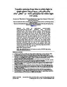
Fig. 1.
Schematic diagram of the industrial robot.
Although the basic idea of LIST was already presented in [14] with simple simulations and experiments, auxiliary techniques are needed for LIST to be more practical. This paper, therefore, represents techniques for practical application of LIST including an application strategy for MIMO systems with coupling, parameter updating scheme for nonlinear time-varying systems, and a selection method for initial guesses of IST parameters. In addition, this paper presents analytical verification for convergence of LIST. Since vibration in the first joint is substantially large and time varying, LIST is applied only to the first joint and conventional IST to the second and third joints. We use the input/output value of the first joint for the learning process so that its nonlinear and time-varying residual vibrations can be suppressed without a dynamic model of the robot. The experimental results of iterative LIST are compared to those of TVIST, and their merits and demerits are evaluated. This procedure can be used as a practical guideline for various industrial robots other than ours. This paper is organized as follows. Section II describes the dynamics of the industrial robot and discusses IST application strategy for the robot. Section III shows its nonlinear and timevarying vibrations and presents the main idea and algorithm of the iterative LIST. Section IV describes our experimental results, and discussion is followed by conclusions in Section V. II. UNDERSTANDING OF A ROBOT DYNAMICS FOR LIST APPLICATION In this section, the dynamic properties of the robot are described in order to show the nonlinear and time-varying characteristics of the robot, and a strategy to apply IST for the robot is presented. A. Robot Dynamics The industrial robot of our interest has a parallelogramlinkage structure with six degrees of freedom (6 DOF). The schematic diagram of the robot is shown in Fig. 1 and its estimated parameters are presented in Table I. As can be expected from the numerical values of these parameters, the robot is intended for handling heavy payloads or spot welding with the maximum payload of 120 kg. To examine its frequency variation properties, the dynamic equation of the robot was derived based on the schematic diagram depicted in Fig. 1. Note that these last three axes have little effect on inertia variation and, thus, on frequency variation.
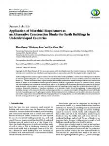
Fig. 2.
Model of joint flexibility.
Therefore, the dynamic equations are derived only for the first three joints. Since joint flexibility is the primary cause of robot vibration, it is included in the model. The flexibility of the ith joint is modeled as a torsional spring with stiffness KT i [13]. Accordingly, each axis also includes two joint variables representing both motor angle (θm i ) and link angle (θi ), as shown in Fig. 2. The dynamic equations for this robot are derived by using Lagrange’s method and described as follows: M11 θ¨m 1 + bm 1 θ˙m 1 +
bk 1 ˙ KT 1 θr 1 = τ1 (1) θr 1 + r1 r1
˙ =0 M22 θ¨1 + b1 θ˙1 − bk 1 θ˙r 1 − KT 1 θr 1 + N1 (θ, θ) M33 θ¨m 2 + bm 2 θ˙m 2 +
(2)
bk 2 ˙ KT 2 θr 2 = τ2 (3) θr 2 + r2 r2
M44 θ¨2 + M46 θ¨3 + b2 θ˙2 − bk 2 θ˙r 2 − KT 2 θr 2 ˙ + G2 (θ) = 0 +N2 (θ, θ)
(4)
bk 3 ˙ KT 3 θr 3 = τ3 (5) θr 3 + M55 θ¨m 3 + bm 3 θ˙m 3 + r3 r3 M64 θ¨2 + M66 θ¨3 + b3 θ˙3 − bk 3 θ˙r 3 − KT 3 θr 3 ˙ + G3 (θ) = 0 +N3 (θ, θ)
(6)
˙ denotes where θr i = ( θrmi i − θi ), θ = [θ1 θ2 θ3 ]T ; and Ni (θ, θ) the Coriolis and centrifugal torque and Gi (θ) the gravity torque ˙ and Gi (θ)s are shown in Appendix I. at the ith joint; Ni (θ, θ)s In the equations above, it is assumed that viscous damping with a coefficient of bm i is also present at each motor, bi at each joint, and bk i at each torsional spring. Under the assumption that each link has a uniform and symmetric cross section, the elements of inertia matrix Mij (θ)s
PARK et al.: INPUT SHAPING TECHNIQUE FOR AN INDUSTRIAL ROBOT
57
can be expressed as the following: M11 = Jm 1
(7) 2
2
2
M22 = (ma lg a + Ja + Jc )c2 + (mb lg b + Jb + Jd )c3
2
+ mc (lb c3 − lg c c2 )2 + md (lc c2 + lg d c3 )2 + mP {lc c2 + (ld − lb )c3 }2
(8)
M33 = Jm 2
(9)
M44 = ma lg a 2 + Ja + mc lg c 2 + Jc + md la 2 + mP la 2 (10) M46 = {md la lg d − mc lb lg c + mP la (ld − lb )} cos(θ2 − θ3 ) (11) M64 = M46
(12)
M55 = Jm 3
(13)
M66 = mb lg b + Jb + mc lb + md lg d + Jd + mP (ld − lb )2 2
2
2
(14) where lk and lg k (k = a, b, c, d), as shown in Fig. 1, denote the length of the corresponding link and the length to the center of gravity of the link, respectively. In the same manner, mk and Jk represent the mass and moment of inertia of the link, respectively. In addition, mP denotes the payload, attached to the endeffector, and ci and si symbolize cos θi and sin θi , respectively. Note in (8) and (11) that M22 and M46 vary with both θ2 and θ3 , whereas (10) and (14) show that M44 and M66 are constant. Owing to M22 and M46 , hence, the robot has time-varying vibrations [15]. The vibration is not only time varying, but also nonlinear due to robot dynamics such as nonlinear spring characteristics of harmonic drive and friction. Moreover, nonlinear terms in dynamic equations, such as Coriolis, centrifugal, and gravity torque, cause nonlinear residual vibration of the robot. As an example, let us examine N1 , which can be expressed in the following form: ˙ = f1 (θ2 , θ3 , θ˙2 , θ˙3 )θ˙1 . N1 (θ, θ) (15) ˙ ˙ ˙ Since f1 (θ2 , θ3 , θ2 , θ3 ) is a nonlinear function, N1 (θ, θ) can be regarded as a nonlinear damper with a nonlinear damping coefficient. Therefore, we can see that the nonlinear terms in N1 cause nonlinear residual vibration of the robot. Due to such time-varying and nonlinear characteristics, residual vibrations of industrial robots are not well suppressed by conventional IST, which was derived for linear time-invariant (LTI) systems [8]–[10], [12]. To this end, we may apply modified versions of the IST technique for the robot. The authors, however, found that, with properly tuned IST parameters, conventional IST can suppress residual vibration in nonlinear and time-varying systems [14], [16]–[18]. Since conventional IST does not require intensive computational time or large memory space, we employed IST to suppress the residual vibration of the industrial robot. B. IST Application Strategy for the Robot The dynamic equations above clearly show that the robot is a multivariable system. Nevertheless, the following observations
are drawn from the analysis of dynamic equations of the robot and experimental verification. 1) For axes 1, 2, and 3, the variation of IST parameters in one axis has little effect on the residual vibration of the other two. For example, even though the IST parameters of axis 1 are changed, the residual vibration in axes 2 and 3 are affected only slightly (Appendix II). 2) Residual vibration in axis 1 is dominant while those in axes 2 and 3 are relatively small (see Fig. 10). Based on these observations, we have developed a strategy to determine IST parameters as follows. 1) Apply conventional IST to axes 2 and 3. Although the residual vibrations in axes 2 and 3 are not eliminated entirely with conventional IST, the remaining vibrations are negligible so that conventional IST can be used in these axes without fine tuning. 2) Tune IST parameters for axis 1 by applying iterative learning algorithm. III. ITERATIVE LEARNING INPUT SHAPING TECHNIQUE A. IST and Measures of Residual Vibrations The two-impulse sequence for suppression of the residual vibration is given in the following general form: � � (16) u(s) = A1 e−T 1 s + A2 e−T 2 s r(s) where r(s) is a reference trajectory. The two-impulse sequence u(s) has four parameters: the magnitudes of impulses A1 and A2 , and the application time T1 and T2 . Without loss of generality, T1 may be fixed to 0 for a faster response, and A2 may also be fixed to (1 − A1 ) in order to maintain a unit gain. Then, there remain only two independent parameters to be determined, A1 and T2 . According to Singer and Seering’s study [3], the residual vibrations due to the two-impulse sequence vanish if A1 and T2 are properly selected by the following equations:
T2n
1
√ 2 1−ζ 1+e π � = ωn 1 − ζ 2
A1n =
−ζ π /
(17) (18)
where ( · )n denotes the exact values of ( · ), and ζ and ωn mean the damping ratio and the natural frequency of the residual vibration to be suppressed, respectively. When A1 �= A1n or T2 �= T2n , however, the residual vibration does not vanish after the application time T2 . For examples, we examined the responses for four cases: T2 > T2n and T2 < T2n for A1 = A1n , and A1 > A1n and A1 < A1n for T2 = T2n . Fig. 3 shows the responses to the two-impulse sequence for these four cases. In the figure, the solid lines represent the original vibration, the unit impulse response without IST, and the dotted lines represent the resultant responses to the two-impulse sequence. Fig. 3(a) shows the response for the case T2 > T2n , and Fig. 3(c) for the case T2 < T2n ; Fig. 3(b) for the case A1 > A1n , and Fig. 3(d) for the case A1 < A1n . Both responses show that the residual vibrations still persist and
58
IEEE/ASME TRANSACTIONS ON MECHATRONICS, VOL. 11, NO. 1, FEBRUARY 2006
Fig. 3. Responses to the two-impulse sequence with inaccurate parameters. Solid lines represent unit impulse responses; dashed lines represent the resultant responses to the two-impulse sequence with T 2 �= T 2n or A 1 �= A 1n . TABLE II OBSERVED RANGES OF φ FOR NINE POSSIBLE CASES
that there exist phase differences from the original vibration without IST. In order to adopt a learning scheme for IST, we have used two measures: the magnitude and phase difference of residual vibration. More specifically, the magnitude measure M is defined as � tf |ν(t)| dt (19) M≡ ti
where ν(t) is any signal representing residual vibration such as position, velocity, or acceleration. ti ≤ t ≤ tf is the duration when the residual vibration is significant. Another measure, φ, is the phase difference between the residual vibrations with and without IST. Examples of φ for improper sets of T2 are shown in Fig. 3. When T2 is larger than the proper value, φ has a positive value or phase lead as shown in Fig. 3(a). On the other hand, when T2 is smaller than the proper value, φ then has a negative value or phase lag as shown in Fig. 3(c). Hence, by observing φ, we can determine whether an IST parameter is larger or smaller than the proper value. Table II shows the observed ranges of φ for nine possible cases of improper A1 and T2 . In order to put the observation above into a broader perspective, we draw the simulation plots of M and φ for two cases:
with T2 varying while A1 is fixed as in Fig. 4(a); and with A1 varying while T2 is fixed as in Fig. 4(b). Fig. 4(a) shows that the magnitude and the phase vary in nonlinear fashions, with M having local minima at T2 = T2n , 3T2n , 5T2n , . . . (or TT2n2 = 1, 3, 5, . . .) [19]. Accordingly, we have restricted the limit 0 ≤ T2 ≤ 2T2n throughout the learning process. In this region, M has only one minimum without any additional local minima, thereby enabling us to apply a function minimization method for parameter update. The range of A1 , 0 ≤ A1 ≤ 1, is determined by (17), and Fig. 4(b) shows that M and φ vary linearly for the range. For this reason, the convergence of A1 has posed little difficulty. B. Iterative Learning Scheme The iterative learning scheme updates the IST parameters A1 and T2 by using M and φ obtained from the experiment (or simulation) with parameters from the previous execution. The overall algorithm is summarized as follows: With an initial guess of A1 and T2 , update T2 first while keeping A1 fixed, until M reaches its minimum; then update A1 with keeping T2 fixed; alternate the updating of A1 and T2 until a satisfactory M is obtained. The phase difference φ is examined only to determine the update rule as explained in the next section. 1) Parameter Update: For convenience, let p denote a parameter to be updated, A1 or T2 , with pk denoting p at the kth iteration and Mk denoting M obtained from an experiment (or simulation) by using pk . The iterative learning scheme is to find pn , the proper parameter to minimize M , which has a shape shown in Fig. 5(a). Thus,
PARK et al.: INPUT SHAPING TECHNIQUE FOR AN INDUSTRIAL ROBOT
59
Fig. 4.
Variation of M and φ: (a) for T 2 varying with A 1 fixed, (b) for A 1 varying with T 2 fixed.
Fig. 5.
˜. The shape of M and M
Fig. 6. (a) A minimum is in the interval [b, c] if f (d) < f (b) or (b) a minimum is in the interval [a, d] if f (b) < f (d).
updating the IST parameters may be regarded as a function minimization and various function minimization techniques can be used to this end. From a different perspective, however, the parameter updating may be viewed as a root finding problem and various root finding methods can be utilized for this purpose. To elaborate, define a ˜ as eM ˜ = M sign(pn − p) M where
� 1, sign(x) =
0, −1,
(20)
if x > 0 if x = 0 if x < 0.
˜ as a function of p. Note that the condition, Fig. 5(b) shows M ˜ = 0 when p = pn , and thus we sign(x) = 0 if x = 0, makes M can use root finding methods for parameter updates. In parameter updating, we have made use of a well established function minimization method called the golden section search [20] in conjunction with a root finding method called the secant method [21]. The latter was used to increase the speed of convergence for the former. Briefly summarizing, the golden section search is based on the fact that a minimum can be found when there is a triplet of points, a < b < c, such that f (b) is less than both f (a) and f (c). In this case, the function has a minimum in the interval [a, c]. With this idea, one can narrow down the interval by choosing a new point d between a and b or between b and c. Let us suppose that d is chosen between b and c. Then we know that a minimum is in the interval [b, c] if f (d) < f (b) as in Fig. 6(a); or a minimum is in the interval [a, d] if f (b) < f (d) as shown in Fig. 6(b). As the process above is repeated with a new triplet b < d < c or
˜ is discontinuous near p n , p k +1 obtained by (21) may be too far Fig. 7. If M from p n .
a < b < d, the interval in which f (x) has a minimum can be narrowed down. In the golden section search, the new point d in a given interval is called the golden mean point since it is normally selected as a golden mean of the given triplet [21]. Instead of using the golden mean point method, however, the secant method is used to increase the speed of convergence. This is possible because we know the sign of ek from φ, where ek = pn − pk . In the secant method, pk +1 is calculated from pk +1 = pk + (pk − pk −1 )
˜k M ˜ k −1 − M ˜k M
(21)
˜ j is the M ˜ obtained from experiment or simulation where M using pj . ˜ is The secant method, however, does not work well when M not continuous near pn as shown in Fig. 7, because it assumes the ˜ is discontinuous function to be smooth near the root [21]. If M near pn , (21) determines pk +1 far from pn as shown in Fig. 7.
60
IEEE/ASME TRANSACTIONS ON MECHATRONICS, VOL. 11, NO. 1, FEBRUARY 2006
Fig. 8. p k +1 is not in the interval where M has a minimum when the parameter is updated improperly. Fig. 9. Experimental setups used for the LIST. The learning process is done on the IBM-PC 486.
As a remedy to overcome this difficulty, the following constraint is added: |pk +1 − pk | ≤ |pk − pk −1 |.
(22)
˜ is discontinuous near pn , the following As a result, when M equation is used instead of (21): � � ˜k M (23) pk +1 = pk + (pk − pk −1 )sat ˜ k −1 − M ˜k M where sat(x) is a saturation function such that � x, if |x| < 1 sat(x) = sign(x), otherwise. We have proved that the updating scheme described thus far makes pk converge to pn as iteration proceeds. The proof is presented in Appendix III. 2) Updating Rule for Varying Frequencies: For some nonlinear systems, the phase difference φ is not reliable any more. For example, a spring-mass system with a nonlinear spring vibrates with decreasing frequencies as the amplitude becomes smaller, and it is of no use to measure φ between vibrations that have different frequencies. In the case of nonlinear systems with vibrations of varying frequencies, therefore, we use a simple trial-error method such as the following instead of using φ for parameter update: Assume that both pk and pk −1 are either larger or smaller than pn , that is, ek ek −1 > 0. Let us apply this assumption to (23) and obtain the following equation to calculate pk +1 : pk +1 = pk + (pk − pk −1 )
Mk sign(ek ) × sat Mk −1 sign(ek −1 ) − Mk sign(ek )
Mk . (24) = pk + (pk − pk −1 )sat Mk −1 − Mk If pk +1 obtained from (24) is in the interval in which M has a minimum, 1 our assumption is confirmed to be correct, and the learning proceeds to the next cycle. On the contrary, if the pk +1 is not in the interval in which M has a minimum (as shown in Fig. 8), it indicates that the pk +1 was not properly updated, that is, the assumption is wrong. Hence, applying ek ek −1 < 0 to 1 It
was explained with the golden section search.
(23), we can obtain the following equation to calculate pk +1 :
Mk pk +1 = pk − (pk − pk −1 )sat . (25) Mk −1 + Mk Although this method increases the iteration numbers and delays the convergence of M , it enables us to obtain exact pk +1 without φ. 3) Selection of Initial Parameters: The initial guesses of A1 and T2 can be calculated using Singer’s method [3]. Although this method is derived from and intended for LTI systems, we find that they still provide good initial guesses for nonlinear time-varying systems. At the second iteration, p1 cannot be obtained by using the updating rule mentioned above because it requires two previous experimental results. The new updating rule for p1 is made in the following form: p1 = p0 − sign(e0 )p0 δ
(26)
where δ denotes a heuristically determined constant less than one. In our learning process, we use δ = 0.1 and sign(e0 ) is obtained from the initial phase difference φ0 . 4) Condition for Minimum M : As mentioned above, we can ˜ has a narrow down the interval where M has a minimum—or M root—through the learning process. We can say that M has converged to its minimum if the interval is sufficiently small so that pU − p L <
(27)
where pU and pL denote the upper and lower bound of the interval, respectively and the predefined error bound. IV. EXPERIMENT A. Experimental Setup Experiments were performed to verify that iterative LIST is effective for suppression of residual vibrations in a robot conducting repetitive tasks. For the experiments, the reference trajectory with its trapezoidal velocity profile was given, and the results of iterative LIST were then compared to those of both conventional IST as well as TVIST based on Rappole’s method [10], [15]. The schematic diagram of the experimental setup is shown in Fig. 9. As position controllers, proportional controllers with inner PI velocity control loops run in a stand-alone robot controller at sampling frequency 2 kHz. An accelerometer, from
PARK et al.: INPUT SHAPING TECHNIQUE FOR AN INDUSTRIAL ROBOT
61
Fig. 10. Experimental results: residual vibration without IST. Note that the robot moved for 1.35 s and the tip response after 1.35 s is the residual vibration.
PCB Piezotronics, Inc., is attached at the tip of the robot to measure the residual vibrations of the tip. As shown in Fig. 9, IST is implemented on the robot controller, whereas the learning algorithm is carried out in the outside controller, an IBM PC 486DX2-66. While the robot is moving, the acceleration signals sensed by the accelerometer are sent to the PC. Then the signals are read by an A/D converter at sampling frequency 200 Hz and filtered through a bandpass filter to filter out both drift signals and noise. The filtered acceleration signals are stored in the PC memory. After one cycle of motion, the PC calculates M and φ, and updates the IST parameters. The values of the updated IST parameters are sent to the robot controller, and the next cycle begins. Prior to the application of IST filters for the robot, we examined the level of the residual vibrations without IST filters. In these experiments, the reference trajectories were given as S-curves with trapezoidal velocity profiles. Fig. 10 shows the tip acceleration signal processed through a filter with a bandwidth between 2–30 Hz, when only feedback control is used. The robot traveled for 1.35 s and the tip response after 1.35 s is regarded as the residual vibration. As is shown in the figure, the residual vibrations in the swing direction, which were caused by the axis 1’s movement, are substantially larger than those in other directions. The experiment above made us observe that the frequency of residual vibration decreases with smaller amplitude whereas the damping ratio remains nearly constant. The frequency variation, in our study, is caused by both the time-varying inertia due to change of the robot’s configuration and the nonlinear flexibility in the harmonic drive. In order to demonstrate the effectiveness of iterative LIST, two other schemes of IST have been compared: conventional IST and the TVIST based on Rappole’s method [10], [15], respectively. They are described as follows. 1) If For adopting conventional IST to nonlinear time-varying systems, we have designed an IST filter using the mean value of varying frequencies. 2) If The TVIST is represented by u(t) = A1 r(t) + A2 r(t − T2 (t)).
(28)
The second impulse varies with time, and its application time T2 (t) is estimated in real time from the position data of each axis.
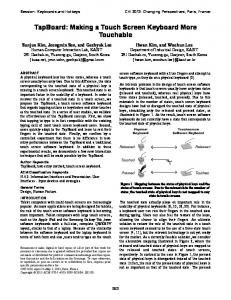
Fig. 11. Experimental results. Magnitude measure M decreases as the number of iterations increases.
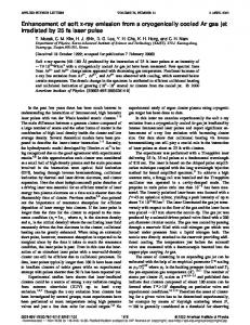
Fig. 12. Tip acceleration measured in swing direction (axis 1). Both TVIST and LIST have suppressed the residual vibrations. Note that because the robot moved for 1.35 s, the tip acceleration after 1.35 s is the residual vibration.
B. Experimental Results Fig. 11 shows the experimental results of the proposed iterative LIST. With the initial parameters, the magnitude of the residual vibration is quite large. As the number of iterations increases, the residual vibrations become smaller and M reaches its minimum at the sixth iteration. Note that tip acceleration is used as ν(t) to calculate M using (19). In Fig. 12, the results of iterative LIST are compared with those of TVIST. LIST and TVIST reduced the peak residual vibration to 14% and 13% of the original vibration without IST, respectively, whereas IST reduced it only to 40%. Therefore, the comparison displays that both iterative LIST and TVIST have well suppressed the residual vibrations, which implies that we can choose any of the two schemes according to application conditions. If the real-time estimation of the varying frequency is both possible and affordable, TVIST is applicable; if not, and the task is repetitive, iterative LIST is suitable. Although higher frequency vibrations exist in the transient region, their amplitudes are very small. In our application, such vibrations in the transient region were not important because this robot was designed for point-to-point motion. Therefore, we believe that LIST is useful for the repetitive tasks which consist of point-to-point motions. V. CONCLUSION For suppression of nonlinear and time-varying residual vibrations in a 6-DOF industrial robot, we have proposed an iterative LIST which updates the parameters of IST by using data from previous trials. Based on theoretical analysis and
62
IEEE/ASME TRANSACTIONS ON MECHATRONICS, VOL. 11, NO. 1, FEBRUARY 2006
experiments, LIST is applied to the first axis of the robot and conventional IST is applied to the second and third axes. As a result, the application of iterative LIST become convenient because the iterative learning scheme is applied only for the swing axis, which exhibits significant time-varying frequencies and large vibrational amplitudes. Experimental results show that iterative LIST reduces the nonlinear and time-varying residual vibrations in the robot as effectively as TVIST does. The LIST is useful for repetitive tasks of industrial robots where real-time estimation is not available, whereas TVIST is effective for nonrepetitive tasks by changing the IST parameters in real time according to the estimated frequency. The iterative LIST is a promising technique to suppress the nonlinear and time-varying residual vibrations in industrial robots, which have a limited computing power and memory space in most cases, because it does not require real-time estimation of vibration frequencies.
Fig. 13. An example of reference trajectories and responses used in simulations.
G3 (θ) = {−mb lg b − mc lb + md lg d + mP (ld − lb )}c3 g where g denotes the gravitational acceleration constant. APPENDIX II
APPENDIX I ˙ AND Gi (θ) Ni (θ, θ) Ni s and Gi s in Section II are shown in the following equations:
SIMULATION Simulations were performed to validate the application strategy proposed in Section II-B with the dynamic model of (1)–(6) and parameters listed in Table I and in the following: Jm 1 = 0.015 kg · m2
˙ N1 (θ, θ)
� = −2 ma lg2a c2 s2 + Ja c2 s2 − mc lg c s2 (lb c3 − lg c c2 ) + Jc c2 s2 + md lc s2 (lc c2 + lg d c3 ) + mP lc s2 {lc c2 + (ld − lb )c3 }] θ˙1 θ˙2 � − 2 mb lg2b c3 s3 + Jb c3 s3 + mc lb s3 (lb c3 − lg c c2 ) + md lg d s3 (lc c2 + lg d c3 ) + Jd c3 s3
Jm 2 = Jm 3 = 0.01 kg · m2
r1 = r2 = r3 = 100 KT 1 = KT 2 = KT 3 = 1.0 × 10⁸ N · m b1 = b3 = 2000 N · m · s b2 = 200 N · m · s bm 1 = bm 2 = bm 3 = 50 N · m · s bk 1 = bk 2 = bk 3 = 2000 N · m · s
+ {−mc lb lg c + md la lg d + mP la (ld − lb )}
where motor inertias and gear reduction ratios were given as robot specifications. Spring and friction constants were estimated from experimental results. Each joint was controlled by a proportional–integral– derivative (PID) position controller, and a reference trajectory for the PID controller was shaped by IST. Fig. 13 shows an example of reference trajectories and responses of joints in simulations. The inner-loop PID controller has the following form: � τi = kP i (θdi − θi ) + kD i (θ˙di − θ˙i ) + kI i (θdi − θi ) dt
× sin(θ2 − θ3 )θ˙32
where their control gains were tuned as follows:
+ mP (ld − lb )s3 {lc c2 + (ld − lb )c3 }] θ˙1 θ˙3 ˙ N2 (θ, θ) � = ma lg2a c2 s2 + Ja s2 − mc lb lg c c3 s2 + mc lg2c c2 s2 + Jc s2 + md lc2 c2 s2 + md lc lg d s2 c3 + mP lc2 c2 s2 + mP lc (ld − lb )s2 c3 } θ˙12
˙ N3 (θ, θ) � = mb lg2b c3 s3 + Jb s3 − mc lb2 c3 s3 − mc lb lg c c2 s3 + Jd s3 + md lg2d c3 s3 + md lc lg d s2 s3
+ mP (ld − lb ) c3 s3 + mP lc (ld − lb )c2 s3 θ˙12 2
+ {mc lb lg c − md la lg d − mP la (ld − lb )} × sin(θ2 − θ3 )θ˙22 G2 (θ) = (ma lg a + mc lg c + md la + mP la )c2 g
kP 1 = 12 × 106 , kI 1 = 8 × 10⁷ , kD 1 = 2000,
kP 2 = kP 3 = 24 × 106 kI 2 = kI 3 = 16 × 107
kD 2 = kD 3 = 4000.
Sampling time for all simulation was fixed to 0.5 ms. In the first simulation the robot moved without IST and resulted in large residual vibrations as shown in Fig. 14. Since the settling time was about 0.85 s for the given trajectories (Fig. 13), vibrations after 0.85 s are regarded as residual vibrations. The second simulation was performed with IST that was designed independently for each joint based on the results of the first
PARK et al.: INPUT SHAPING TECHNIQUE FOR AN INDUSTRIAL ROBOT
63
Fig. 15. Three different cases in updating parameters.
compared with those of residual vibrations without IST. The simulation results exhibit that the peak amplitude of residual vibrations in axes 2 and 3 varied only by 1% to 3%, while the IST parameter in axis 1 had a negligible effect on the residual vibration of the other two axes. APPENDIX III CONVERGENCE OF LIST Fig. 14. Residual vibrations with various IST parameters of axis 1: θi − θm i after settling time (a) without IST, (b) with IST, and (c) with IST parameter variation in axis 1. Note that dashed and thick solid lines overlap each other in axes 2 and 3.
TABLE III TRAJECTORIES AND SIMULATIONS RESULTS
For the purpose of verifying the convergence of the proposed updating rule, the error (p − pn ) is examined. First, the updating condition is divided into the following two cases for examination. Case 1) Both pk −1 and pk are smaller or larger than pn as shown in Fig. 15(a). Case 2) Either pk −1 or pk is smaller than pn and the other is larger than pn as shown in Fig. 15(b). Without loss of generality, we considered a situation represented in Fig. 15(a) for Case 1. By subtracting pn from both sides of (23), we obtain � � ˜k M ek +1 = ek + (pk − pk −1 )sat (29) ˜ k −1 − M ˜k M ˜k < M ˜ k −1 , where ej = pj − pn . Since pk −1 < pk < pn and M we know that ek < 0,
pk − pk −1 > 0,
With these inequalities, (29) can be ek +1 = −|ek | + (pk − pk −1 )sat
simulation. As shown in Fig. 14, residual vibrations in axes 2 and 3 were reduced to 17.6% and 18.2% of the original vibration, respectively. The next simulation was to examine the variation of residual vibrations in axes 2 and 3 with a change of IST parameters in axis 1. IST parameters in axis 1, therefore, were decreased by 50% while keeping those in axes 2 and 3 constant. Comparing the results with those of the second simulation, we observed that there were very little differences. More simulations were performed with various trajectories as listed in Table III. The values summarized in the table represent the maximum peak-to-peak amplitude of residual vibrations
˜ k −1 − M ˜ k > 0. M �
˜k M ˜ k −1 − M ˜k M
� .
(30)
If pk +1 < pn as shown in Fig. 15(a-1), the following inequality is obtained from (30): � � ˜k M |ek +1 | = |ek | − (pk − pk −1 )sat < |ek |. ˜ k −1 − M ˜k M (31) On the other hand, if pk +1 > pn as shown in Fig. 15(a-2), the following inequality holds from (30): � � ˜k M |ek +1 | = −|ek | + (pk − pk −1 )sat ˜ k −1 − M ˜k M ≤ −|ek | + (pk − pk −1 ) = −2|ek | + |ek −1 | < |ek −1 |.
(32)
64
IEEE/ASME TRANSACTIONS ON MECHATRONICS, VOL. 11, NO. 1, FEBRUARY 2006
Equations (31) and (32) can be combined as follows: |ek +1 | < max[|ek |, |ek −1 |].
(33)
Moreover, (33) can be represented as (34) by introducing a constant ck +1 which satisfies 0 < ck +1 < 1: |ek +1 | < ck +1 max[|ek |, |ek −1 |].
(34)
In Case 2, we obtain the following equation from (21):
ek +1 =
˜ k −1 ek − M ˜ k ek −1 M . ˜ k −1 − M ˜k M
(35)
˜ k −1 < 0 as shown in Fig. 15(b), ˜k M Since ek ek −1 < 0 and M (35) becomes |ek +1 | = ≤
˜ k �ek −1 � ˜ k −1 �ek | − |M �M ˜ k −1 | + |M ˜k | |M ˜k � ˜ k −1 | − |M �M max(|ek |, |ek −1 |) ˜ ˜k | |Mk −1 | + |M < ck +1 max(|ek |, |ek −1 |)
(36)
˜ k −1 |, |M ˜ k |))/ where ck +1 is a constant which satisfies (max (|M ˜ k |) < ck +1 < 1. ˜ k −1 | + |M (|M From (34) and (36), we can say that |ek +1 | has the following inequality: |ek +1 | < cM max(|ek |, |ek −1 |)
(37)
where cM is a maximum value among all cj s for j = 2, 3, . . . , ∞. By using (37), |ej | for j = 2, 3, 4, . . . , k is represented as follows: |e2 | < cM eM |e3 | < cM max(|e1 |, |e2 |) < cM eM .. . |ek | < ckM−2 eM where eM = max(|e0 |, |e1 |). As a result, lim |ek | < lim ckM−2 eM = 0.
k →∞
k →∞
(38)
In other words, pk converges to pn as iteration proceeds. REFERENCES [1] H. Asada, Z.-D. Ma, and H. Tokumaru, “Inverse dynamics of flexible robot arms of trajectory control,” in Proc. Modeling and Control of Robotic Manipulators, 1987 ASME Winter Annu. Meeting, 1987, pp. 329–336. [2] P. T. Kotnik, S. Yurkovich, and U. Ozguner, “Acceleration feedback for control of a flexible manipulator arm,” J. Robot. Syst., vol. 5, no. 3, pp. 181–196, Jun. 1988. [3] N. C. Singer and W. P. Seering, “Preshaping command inputs to reduce system vibration,” Trans. ASME, J. Dyn. Syst. Meas. Control, vol. 112, pp. 76–82, 1990. [4] M. Ballesteros and W. Book, “Implementation alternatives for dual rate control systems with command shaping,” in Proc. American Control Conf., 2002, pp. 2285–2291.
[5] M. Agostini, G. G. Parker, K. Groom, H. Schaub, and R. D. Robinett, “Command shaping and closed-loop control interactions for a ship crane(I),” in Proc. 2002 American Control Conf., 2002, pp. 2298–2304. [6] P. H. Chang and J. Park, “A concurrent design of input shaping technique and a robust control for high-speed/high-precision control of a chip mounter,” Control Eng. Practice, vol. 9, no. 12, pp. 1279–1285, Dec. 2001. [7] J. T. Feddema et al., “Control for slosh-free motion of an open container,” IEEE Control Syst. Mag., vol. 17, no. 1, pp. 29–36, Feb. 1997. [8] A. Tzes and S. Yurkovich, “An adaptive input shaping control scheme for vibration suppression in slewing flexible structures,” IEEE Trans. Contr. Syst. Technol., vol. 1, no. 2, pp. 114–121, Jun. 1993. [9] M. Bodson, “An adaptive algorithm for the tuning of two input shaping methods,” in Proc. American Control Conf., vol. 3, 1997, pp. 1340–1344. [10] B. W. Rappole, “Minimizing residual vibrations in flexible systems,” Master’s thesis, Dept. Mech. Eng., MIT, Cambridge, MA, 1992. [11] D. P. Magee and W. J. Book, “Implementing modified command filtering to eliminate multiple modes of vibration,” in Proc. 1993 American Control Conf., Jun. 1993, pp. 2700–2704. [12] J. K. Cho and Y. Park, “Vibration reduction in flexible systems using a time-varying impulse sequence,” Robotica, vol. 13, pp. 305–313, 1995. [13] R. Kinceler and P. H. Meckl, “Corrective input shaping for a flexible-joint manipulator performing point-to-point motion,” in Proc. IEEE Int. Conf. Control Applications, 1996, pp. 391–396. [14] J. Park and P. H. Chang, “Learning input shaping technique for non-LTI systems,” Trans. ASME, J. Dyn. Syst. Meas. Control, vol. 123, pp. 288– 293, Jun. 2001. [15] H. S. Park, P. H. Chang, and J. S. Hur, “Time-varying input shaping technique for an industrial robot,” in Proc. IEEE/RSJ Int. Conf. Intelligent Robots and Systems, vol. 1, 1999, pp. 285–290. [16] J. Y. Smith, K. Kozak, and W. E. Singhose, “Input shaping for a simple nonlinear system,” in Proc. American Control Conf., 2002, pp. 821–826. [17] J. Park, P. H. Chang, and E. Lee, “Can a time invariant input shaping technique eliminate residual vibrations of LTV systems?,” in Proc. 2002 American Control Conf., 2002, pp. 2292–2297. [18] J. Park and C. B. Schrader, “Can an input shaper with two impulses suppress nonlinear residual vibrations?,” in Proc. 2003 American Control Conf., 2003, pp. 3172–3177. [19] T. Singh and S. R. Vadali, “Robust time-delay control,” Trans. ASME, J. Dyn. Syst. Meas. Control, vol. 115, no. 2, pp. 303–306, 1993. [20] W. H. Press, B. P. Flannery, S. A. Teukolsky, and W. T. Vetterling, Numerical Recipes in C, The Art of Scientific Computing. Cambridge, U.K.: Cambridge Univ. Press, 1988. [21] L. W. Johnson and R. D. Riess, Numerical Analysis, 2nd ed. Reading, MA: Addison-Wesley, 1982.
Juyi Park (M’02) received the B.S. degree in production engineering the M.S. degree in precision engineering, and the Ph.D. degree in mechanical engineering from the Korea Advanced Institute of Science and Technology (KAIST), Daejon, Korea, in 1991, 1993, and 2001, respectively. He was a Postdoctoral Fellow at the University of Texas at San Antonio from 2001 to 2002. From 2002 to 2004, he was a Research Associate in the Department of Electrical Engineering and Computer Science, Vanderbilt University, Nashville, TN. Since, 2004, he has been working on intelligent robot controllers at the Robot R&D Institute, Daewoo Shipbuilding and Marine Engineering Company Ltd., Koje City, Korea. His research interests are suppression of residual vibration in flexible structures, robots for disabled people, and real-time robot controllers.
Pyung-Hun Chang (S’86–M’89) was born in Pusan, Korea, in 1951. He received the B.S. and M.S. degrees from Seoul National University (SNU), Seoul, Korea, in 1974 and 1977, respectively, and the Ph.D. degree from the Massachusetts Institute of Technology (MIT), Cambridge, MA, in 1987, all in mechanical engineering. From 1984 to 1987, he was involved in a research project in the field of robotics as a Research Assistant at the Artificial Intelligence Laboratory of MIT. Since 1987, he has been on the faculty of and is now a
PARK et al.: INPUT SHAPING TECHNIQUE FOR AN INDUSTRIAL ROBOT
Professor in the Department of Mechanical Engineering, Korea Advanced Institute of Science and Technology (KAIST), Daejon, Korea. His research interests are high accuracy/speed control with application to mechanical systems, robust control of nonlinear plants such as robot manipulators, and task-oriented design of robot manipulators.
Hyung-Soon Park was born in Seoul, Korea, in 1972. He received the B.S. degree in precision engineering and the M.S. and Ph.D. degrees in mechanical engineering from the Korea Advanced Institute of Science and Technology (KAIST), Daejon, Korea, in 1994, 1996, and 2004, respectively. He is currently a Research Associate at the Rehabilitation Institute of Chicago, Chicago, IL. His research interests include robust control algorithms, design and control of rehabilitation robots, and teleoperation systems.
65
Eunjeong Lee (S’88–M’94) received the B.S. degree from Ajou University, Suwon, Korea, in 1986, the M.S. degree from Northwestern University, Evanston, IL, in 1989, and the Ph.D. degree from Case Western Reserve University, Cleveland, OH, in 1994, all in mechanical engineering. She is currently a Visiting Professor in the Department of Electrical Engineering and Computer Science at the Korea Advanced Institute of Science and Technology (KAIST), Daejon, Korea. She was an Assistant Professor in the Department of Mechanical Engineering at the University of Texas at San Antonio from 2000 to 2002. Her research interests are biomimetics at the micro/nanoscale, MEMS, intelligent control, and superconducting renewable evergy systems. Dr. Lee received a University of Houston/NASA Johnson Space Center Aerospace Postdoctoral Fellowship (1996–1999) and the Workshop Material/Product Performance Award from the 1997 International Workshop on Superconductivity. She served the IEEE Control Stytems Society as an Associate Editor for the Conference Editorial Board from 2000 to 2002. She is also a member of ASME.