JOURNAL OF OPTOELECTRONICS AND ADVANCED MATERIALS Vol. 10, No. 5, May 2008, p. 1178 - 1183
Design optimization of distribution transformers based on mixed integer programming methodology ELEFTHERIOS I. AMOIRALIS*, PAVLOS S. GEORGILAKIS, MARINA A. TSILIa Department of Production Engineering & Management, Technical University of Crete, GR-73100, Chania, Greece, a Faculty of Electrical & Computer Engineering, National Technical University of Athens, GR-15780, Athens, Greece,
In this paper, an effective optimization method is proposed with the aim of minimizing the active part cost of wound core distribution transformers, taking into account constraints imposed both by international specifications and customer needs. In order to achieve so, Mixed Integer Programming in conjunction with the Branch and Bound technique are employed. The proposed methodology is compared with a heuristic optimization methodology of the transformer manufacturing industry and the results demonstrate the robustness and the superiority of this new approach. (Received March 13, 2008; accepted May 5, 2008) Keywords: Transformer design optimization methodology, Mixed integer programming, branch and bound, Optimization methods, distribution transformer, Wound core type transformer.
1. Introduction With the rapid development of digital computers, transformer designers are released from the drudgery of routine calculations. Within a matter of a few minutes, today’s computers can work out a number of different transformer designs (by varying flux density, core dimensions, current density, type of magnetic material and so on) and come up with an optimum design. In the literature, a number of different transformer design methodologies have been proposed [1][2]. The difficulty in achieving the optimum balance between the transformer cost and performance is becoming even more complicated nowadays, as the main materials used in transformer manufacturing (copper or aluminium for transformer windings, steel for magnetic circuit) are variable stock exchange commodities and their prices are modified on a daily basis. Techniques that include mathematical models employing analytical formulas, based on design constants and approximations for the calculation of the transformer parameters are often the base of the design process adopted by transformer manufacturers [3]. However, the relevant technical literature comprises a variety of other approaches in order to cope with the complex problem of transformer design optimization, based on stochastic optimization methods such as genetic algorithms (GAs) that have been used for transformer cost minimization [4], performance optimization of cast-resin distribution transformers with stack core technology [5] or toroidal core transformers [6]. The computational complexity of artificial intelligence (AI) methods becomes quite considerable due to numerous iterations that may be required in order to achieve overall transformer optimization. Thus, AI methods cannot be easily applied in overall transformer optimization and they are usually focusing on certain aspects of transformer designs, as in [7] and [8], where artificial intelligence techniques are used for winding material selection and
prediction of transformer losses and reactance, respectively. Moreover, the optimality of the solution provided by GAs and other stochastic methods cannot be guaranteed [9] and multiple runs may result to different suboptimal solutions, with a significant difference between the worst and the best one. On the other hand, deterministic methods may provide more robust solutions to the transformer design optimization problem. In this context, the deterministic method of geometric programming has been proposed in [10] in order to deal with the design optimization problem of low frequency as well as high frequency transformers. However, the overall manufacturing cost optimization is scarcely addressed in the technical literature, and the main approaches deal with the optimization of specific cost components such as the magnetic material weight [11] or certain performance parameters as the output power [12]. This work introduces the use of Mixed Integer Programming (MIP) in conjunction with the Branch and Bound (BB) technique so as to minimize the transformer active part cost while meeting international standards and customer needs. The deterministic MIP technique is successfully applied to the overall active part cost minimization, overcoming the deficiencies of complexity of stochastic methods. Moreover, the proposed method finds the global optimum transformer design by minimizing the active part cost while simultaneously satisfying all the constraints imposed by international standards and transformer user needs, instead of focusing on the optimization of only one parameter of transformer performance (e.g., no-load losses or short-circuit impedance). Using the proposed technique, a user-friendly software package is developed that combines transformer design with analysis and optimization tools, useful for both design optimization and educational purposes. The method is applied for the design of distribution transformers of several ratings and loss categories and the results are compared with a heuristic transformer design
Design optimization of distribution transformers based on mixed integer programming methodology
optimization methodology, resulting to significant cost savings. The paper is organized as follows: Section 2 presents the basics of mixed integer programming as well as the proposed transformer design optimization methodology. The results of the proposed method are presented in Section 3. Finally, Section 4 concludes the paper. 2. Proposed methodology 2.1 Mixed Integer Programming In order to find the global optimum of a constrained multivariable function, MIP implements the BB algorithm [13]. The standard form of a nonlinear objective function Z=f(x) with n design variables xj to be minimized by MIP is: Z = min f ( x) = min x
n
∑c j =1
j
⋅ f j ( x)
(1)
subject to the following constraints: n
∑a j =1
ij
x j ≥ 0,
⋅ x j ≤ bi ,
i = 1, 2,..., m
j = 1,2,..., n
(2) (3)
x j ∈N for all or some j = 1,2,..., n
(4)
lb j ≤ x j ≤ ub j ,
(5)
j = 1, 2,..., n
where f is a nx1 matrix of objective functions fj, c is a nx1 matrix of objective function coefficients cj, x is a nx1 matrix of design variables xj, a is a mxn matrix of constraints coefficients, b is a mx1 matrix of the upper values of the constraints, N refers to the set {0, 1, …} , and lb and ub are nx1 matrices of lower and upper bounds on x , respectively. The objective functions fj are calculated through a number of intermediate formulas, which are used for the derivation of the performance parameters influencing the cost of the transformer components. These formulas may be expressed as a single compound objective function, resulting to an overall convex nonlinear optimization problem, expressed with the use of equation (1). 2.2 The Branch and Bound Method
The BB method solves MIP by solving a sequence of linear programming problems obtained by relaxing integrality conditions and including additional constraints. Six steps are used by BB technique in order to deal with MIP problem [13], as follows: 1st step: Set up upper bound ( ∞ ) and lower bound ( −∞ ) of the optimal solution. Solve the initial MIP relaxing integrality conditions. If the relaxed problem is infeasible,
1179
the original MIP is infeasible as well and there is no solution. If the attained solution satisfies integrality conditions it is optimal. Otherwise, the lower bound is updated with the value of the optimal solution attained. 2nd step: Using an integer-to-be variable xk that is not an integer, two branching problems from the original one are generated as follows. If xk is a non-integer value such as a.b, where a and b are its integer and fractional parts, the first branch problem is the relaxed original MIP plus the constrained xk ≤ a and the second branch problem is the relaxed original MIP plus the complementary constraint xk ≥ a+1. Both problems are placed in a processing list and are considered sequentially or parallel. It is important to note that this strategy completely covers the solution space. 3rd step: Solve next problem in the processing list. 4th step: If the solution of the current problem satisfies integrality conditions and its corresponding objective function value is smaller than the current upper bound, the upper bound is updated to the current objective function value and the current minimizer is stored as the best candidate to minimizer. On the other hand, if the solution does not satisfy integrality conditions and the objective function value is in between upper and lower bounds, the lower bound is updated to the objective function value, the current problem is branched, and the generated problems are added to the processing list. 5th step: If the solution provided by the current problem satisfies integrality conditions, no further branching is possible. The branch is therefore cut as a result of integrality. If the solution does not satisfy integrality conditions and the objective value is greater than the current upper bound, no better solution can be obtained further along that branch and therefore it is cut due to bounds. If the current problem is infeasible, no further branching is possible through that branch and it is cut due to infeasibility. 6th step: If the processing list is not empty, we continue with step 3. Otherwise, the procedure terminates. 2.3 Proposed Algorithm
In order to find the global optimum design of a distribution transformer, MIP in conjunction with the BB technique are used. The goal of the proposed optimization method is to find a set of integer variables linked to a set of continuous variables that minimize the objective function (active part cost) and meet the restrictions imposed on the transformer design problem. Under the previous definitions, a mixed integer nonlinear problem for optimizing the transformer design is based on the minimization of the cost of the transformer active part: 4
min x
∑c j =1
j
⋅ f j ( x)
(6)
where c1 is the primary winding unit cost (€/kg), f1 is the primary winding weight (kg), c2 is the secondary winding unit cost (€/kg), f2 is the secondary winding weight (kg), c3
1180
Eleftherios I. Amoiralis, Pavlos S. Georgilakis, Marina A. Tsili
is the magnetic material unit cost (€/kg), f3 is the magnetic material weight (kg), c4 is the insulating paper unit cost (€/kg), f4 is the insulating paper weight (kg), and x is the vector of the four design variables, namely the number of secondary winding turns, the width of core leg (D), the core window height (G), and the magnetic flux density (B). The minimization of the cost of the transformer active part is subject to the following constraints: DNLL + DLL − (1 + Ttot ) ⋅ (GNLL + GLL) < 0 DNLL − (1 + TNLL ) ⋅ GNLL < 0
DLL − (1 + TLL ) ⋅ GLL < 0 (1 − TU ) ⋅ GU < DU < (1 + TU ) ⋅ GU
where: DNLL: DLL: DU: GNLL: GLL: GU: Ttot: TNLL: TLL: TU:
(7) (8) (9) (10)
designed no-load losses (W) designed load losses (W) designed short-circuit impedance (%) guaranteed no-load losses (W) guaranteed load losses (W) guaranteed short-circuit impedance (%) tolerance for the sum of no-load losses and load losses (defined as a percentage of GNLL+GLL) tolerance for the no-load losses (defined as a percentage of GNLL) tolerance for the load losses (defined as a percentage of GLL) tolerance for the short-circuit impedance (defined as a percentage of GU).
the program calculate the minimum acceptable crosssection according to thermal short circuit test method. During the second step (located in the lower section of the form of Fig. 1, entitled “Mixed Integer Programming Input Parameters”), the user must define the initial value of each of the four design variables, as well as the upper and the lower bound value for the four design variables, which are the number of turns of the secondary winding as well as the width and the height of the core leg, and the magnetic flux density (Fig. 1). The total amount of the input MIP design variables is 12. It is important to note that all the design variables can assume not only continuous values but also integer values, by enabling the appropriate Integer check-box (Fig. 1). Having accomplished these two steps, the proposed methodology is used so as to find the design with the minimum active part cost that meets international standards as well as customer needs. MATLAB was chosen as the programming language for the software as it combines an easy-to-use environment for designing Graphic User Interface (GUI) intensive packages. In order to increase the software flexibility, the user is also allowed to modify other parameters, such as the unit cost of the materials of the transformer active part (primary winding, secondary winding, magnetic material, and insulating paper unit cost) selecting the Specifications menu in the menu bar, opening an additional form with default values of input parameters, which may be altered by the user. Moreover, through the Specifications form, the user can modify the load loss tolerances, no-load loss tolerances, total loss tolerances and short-circuit impedance tolerance, as well as some crucial parameters of the MIP method (e.g. maximum allowable number of function evaluations and termination tolerance on the objective function, the design vector or the constraint violation).
It should be noted that functions f1, f2, f3, f4 appearing in the objective function (6) are composite functions of the
(
)
design variables x , e.g., f1 = f1 g1 (h1 ( x)) , that is why the transformer design optimization problem is a hard optimization problem in terms of both modeling and solving. 2.4 Software Design
The aforementioned methodology is implemented by a software package, which has a graphical, user-friendly, interface separated into two main steps, requiring 26 input parameters. During the first step, the user must set 14 technical characteristics of the transformer design (such as the rated power, the rated voltage of the primary and secondary windings, the magnetic material of the core, the vector group, the guaranteed no-load and load losses (the user can choose them either based on CENELEC standard [14] or by his choice), the frequency, and so on (Fig. 1)). As can be observed in Fig.1, the user can either define directly the secondary and primary winding current density, which is used for the conductors’ cross-section calculation, or let
Fig. 1. The initial screen of the transformer design optimization program.
1181
Design optimization of distribution transformers based on mixed integer programming methodology
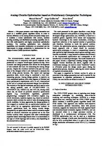
Once the input parameters have been chosen by the user, the optimization is started. The output results are saved in a text file, which contains all the appropriate transformer characteristics, such as the designed load losses, designed no-load losses, the conductors dimensions, the number of turns of the primary and secondary winding, the number of layers of the primary and secondary winding, the total cost of the active part, etc. A two-dimensional cross-section along the symmetry plane of the distribution transformer active part (Fig. 2), corresponding to the optimal solution, is designed as shown in Fig. 3. It should be noted that, due to symmetry, only the left half of the cross-section is shown in Fig. 3.
enhancing the advantages of the developed methodology and software. 3.1 Case Studies
Six actual transformer designs are considered, using a mix of two different loss categories, i.e. BA′ and AC′ according to CENELEC harmonization document HD 428.1 S1:1992 (Table I). The common technical characteristics of these six designs are: the rated primary and secondary voltages are 20/0.4 kV, the vector group is Dyn11, apart from the 50 kVA power rating transformer where the connection group is Yzn5, and the frequency is 50 Hz. The tolerances for the losses and short-circuit impedance are Ttot=10%, TNLL=15%, TLL=15% and TU=10%, based on the tolerances specified by IEC 600761 [15]. Table 1. Technical characteristics of the considered distribution transformers.
Fig. 2. Active part configuration of the three-phase wound core power transformer considered.
Rated Power (kVA)
Loss Category
Load losses (W)
No-load Losses (W)
50 160 400 1000 1600 1600
ΒΑ′ ΒΑ′ ΒΑ′ ΒΑ′ ΒΑ′ AC′
1350 3100 6000 13000 20000 17000
190 460 930 1700 2600 1700
Shortcircuit impedance (%) 4 4 4 6 6 6
Table 2 compares the solutions obtained a) by the proposed methodology, and b) by the current methodology [3] that is based on a heuristic optimization technique. Table 2 shows that the proposed methodology converges to an optimum solution that has on average a 2.67% lower active part cost than the heuristic optimization methodology used by the manufacturer. The difference in the active part cost between the two methods is due to the difference in the permissible range of the design variables, which is confined in the heuristic optimization methodology to discrete steps of the variables instead of the complete intervals used in the proposed methodology. Fig. 3. The 2D cross-section of the active part corresponding to the optimal solution, generated by the computer program using the input parameters shown in Fig. 1. The small and the large core are shown in dark red, while the primary and secondary winding are shown in yellow and orange, respectively.
3. Results and discussion
The robustness of the proposed methodology is verified through comparison with that of heuristic optimization methodology [3], which is already applied in a transformer manufacturing industry. The next paragraphs present the comparison of the results of the proposed method and the heuristic optimization method, as well as a comparison of their performance characteristics, further
Table 2. Active part cost comparison of optimum designs provided by the proposed and the heuristic transformer design methodology.
Rated Power (kVA) – Loss category
Active part cost of the proposed methodology (€)
50-BA′ 160-BA′ 400-BA′ 1000-BA′ 1600-BA′ 1600-AC′
697 1390 2854 5299 6565 7214
Active part cost of the heuristic optimization methodology (€) 699 1429 2994 5351 6842 7461 Mean average
Active part cost reduction vs. heuristic optimization methodology (%) 0.29 2.73 4.68 0.97 4.05 3.31 2.67 %
1182
Eleftherios I. Amoiralis, Pavlos S. Georgilakis, Marina A. Tsili
Fig. 4 presents the comparison of technical characteristics of the optimum designs provided by the proposed and the heuristic optimization method, for all the
a)
considered case studies. Table III presents the optimal value of the design vector for each transformer according to the results of the proposed method.
b)
c)
d)
e)
f)
Fig. 4. Comparison of characteristics of the optimum designs provided by the proposed and the heuristic transformer design methodology, for the a) 50 kVA – BA′ loss category, b) 160 kVA – BA′ loss category, c) 400 kVA – BA′ loss category, d) 1000 kVA – BA′ loss category, e) 1600 kVA – BA′ loss category, f) 1600 kVA – AC′ loss category. Table 3. Transformer design optimization results.
Rate Power (kVA) – Loss category 50-BA′ 160-BA′ 400-BA′ 1000-BA′ 1600-BA′ 1600-AC′
Number of turns
D (mm)
G (mm)
B (Gauss)
57 30 18 13 10 10
155 184 255 287 314 325
155 196 255 296 314 325
18000 18000 18000 18000 18000 17900
3.1 Performance characteristics of the proposed software
Table IV shows the differences between the two methodologies illustrating the advantages of the proposed methodology. The attractive features of the proposed software are that it uses 26 essential input parameters (14 input parameters concerning the transformer characteristics and 12 input parameters concerning the MIP variables) in order to design an optimum transformer, always in less than 90 seconds, necessitating no previous transformer design experience, in contrast with the current software (based on the heuristic technique) that needs 134 input parameters so as to find a possible optimum transformer design in
approximately 3 hours, and requires a lot of experience in transformer design. Moreover, the number of iterations that are required by the proposed program in order to compute an optimum transformer design varies between 10 and 100 (on average, according to the convergence tolerances specified by the user), in comparison with the current program that requires up to 204 iterations (depending on users’ choices for the number of discrete steps of the input parameters). Finally, using the proposed method, it is easy to design an optimum transformer that is approximately 2.67% cheaper than the current technique. 4. Conclusion
In the present paper, a MIP technique using the BB algorithm is proposed for the solution of the distribution transformer design optimization problem. The proposed method is very effective because of its robustness, its high execution speed and its ability to effectively search the large solution space. Moreover, the global optimum obtained by the proposed method is not satisfactorily approached by continuous variable optimization techniques. The validity of the proposed method is clearly illustrated by its application to a wide spectrum of actual transformers, of different power ratings and losses, resulting to optimum designs with an average cost saving of 2.67% in comparison with the existing heuristic methodology used by a transformer manufacturer. Furthermore, the development of userfriendly software based on this method provides significant
Design optimization of distribution transformers based on mixed integer programming methodology
improvements in the manufacturing industry.
design
process
of
the
Table 4. Comparison between the two methods.
Proposed Software
Current Software
1. 26 essential input parameters.
1. 134 input parameters.
2. Average number of iterations 10-100 (according to convergence tolerance).
2. Variable number of iterations (1 to 204 loops).
3. An optimum solution is always found.
3. All the candidate solutions might be rejected.
4. Less than 90 seconds are required to optimize the transformer design (with a common PC and an average number of iterations).
4. Approximately 3 hours are required (multiple executions of the software by the transformer designer).
5. Low experience is required.
5. Expertise in transformer design is required. 6. The proposed software finds an optimum solution that is on average 2.67% cheaper than the current software. Acknowledgment
This paper is part of the 03ED045 research project that is co-financed by E.U.-European Social Fund (75%) and the Greek Ministry of Development-GSRT (25%).
References
[1] C. Hernandez, M. A. Arjona, Proceedings of the 12th Biennial IEEE Conference on Electromagnetic Field Computation, PD5-6, pp. 299, 2006.
1183
[2] J. Breslin, W. G. Hurley, Proceedings of the 7th IEEE Workshop on Computers in Power Electronics, COMPEL 2000, Blacksburg, Virginia, pp. 277-280, 2000. [3] P. S. Georgilakis, M. A. Tsili, A. T. Souflaris, Journal of Materials Processing Technology 181(1-3), 260 (2007). [4] L. Hui, H. Li, H. Bei, Y. Shunchang, Proceedings 5th International Conference on Electrical Machines and Systems, ICEMS 2001 1, 242 (2001). [5] S. Elia, G. Fabbri, E. Nistico, E. Santini, International Symposium on Power Electronics, Electrical Drives, Automation and Motion, SPEEDAM 2006, pp. 1473-1477, 2006. [6] N. Tutkun, A. Moses, Journal on Magnetism and Magnetic Materials 277(1-2), 216 (2004). [7] E. I. Amoiralis, P. S. Georgilakis, T. D. Kefalas, M. A. Tsili, A. G. Kladas, IEEE Transactions on Magnetics 43(4), 1633 (2007). [8] L. H. Geromel, C.R. Souza, IEEE Canadian Conference on Electrical and Computer Engineering, 1, 285 (2002). [9] S. A. Kazarlis, A. G. Bakirtzis, V. Petridis, IEEE Transactions on Power Systems 11(1), 83 (1996). [10] R. Jabr, IEEE Transactions on Magnetics 41(11), 4261 (2005). [11] C. J. Wu, F. C. Lee, IEEE Transactions on Magnetics, 16(5), 755 (1980). [12] F. F. Judd, D. R. Kressler, IEEE Transactions on Magnetics 13(4), 1058 (1977). [13] E. Castillo, A. J. Conejo, P. Pedregal, R. Garcia, N. Alguacil, Building and Solving Mathematical Programming Models in Engineering and Science, Wiley, 2002. [14] CENELEC Harmonization document, HD 428.1 S1:1992. [15] IEC 60076-1, “Power transformers – Part 1: General,” 2000. ______________________ * Corresponding author:
[email protected]