Available online at www.sciencedirect.com Available online at www.sciencedirect.com
Procedia Engineering
Procedia Engineering 00 (2011) 000–000 Procedia Engineering 29 (2012) 4030 – 4034 www.elsevier.com/locate/procedia
2012 International Workshop on Information and Electronics Engineering (IWIEE)
Design Procedures for a Fully Differential Telescopic Cascode Two-Stage CMOS Operational Amplifier M.Y. Rena*, T. Wub, M.X. Songb, C.X. Zhanga b
a School of Software, Harbin University of Science and Technology, Harbin 150080, China School of Applied Sciences, Harbin University of Science and Technology, Harbin 150080, China
Abstract
In this paper, a fully differential telescopic operational amplifier design is presented which achieve both high dc gain and high unity-gain frequency. Trade-offs among such factors as bandwidth, gain, phase, margin, bias current, signal swing, slew rate, and power are made evidently. The characteristic of this kind of two-stage operational amplifier is investigated theoretically, in this paper. The results indicate that proposed two-stage operational amplifier achieves broader unity bandwidth, increases the DC gain. Simulation results show that, at 5V power supply, the output swing is ±4.3 V, settling time is 167.4ns. Based on the two-stage operational amplifier structure, the operational amplifier with 2.5V output common voltage shows a DC gain greater than 87 dB, Gain Bandwidth over 39 MHz (5pF load) and a phase margin larger than 84° with power dissipation of 3mW. These good results could be used in ∑-△ modulation and A/D conversion etc. © 2011 Published by Elsevier Ltd. Selection and/or peer-review under responsibility of Harbin University of Science and Technology Open access under CC BY-NC-ND license. Keywords: CMOS integrated circuits, two-stage amplifier, telescopic cascode
1. Introduction In recent years, the progressive of amplifier technology, designers have put forward higher requirement for the high gain. This paper addresses the need for relatively inexperienced analog integrated circuit,
* Mingyuan Ren. Tel.: +86-451-86397009; fax:+86-451-86397001. E-mail address:
[email protected].
1877-7058 © 2011 Published by Elsevier Ltd. Open access under CC BY-NC-ND license. doi:10.1016/j.proeng.2012.01.614
4031
M.Y. Ren et al. Procedia Engineering 29 (2012) 4030 – 4034 M.Y. Ren, et /al. / Procedia Engineering 00 (2011) 000–000
2
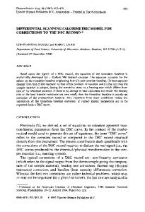
designers to be able to come up with reasonably efficient designs for complex analog building blocks such as the fully differential telescopic cascode amplifier [1] [2]. The small signal dc current gain of telescopic amplifier is more than the simple structure’s small-signal dc current gain [3]. Thus, the telescopic amplifier can easily reach to 60~70dB. But there is a significant defect of telescopic amplifier, namely, limited output swings. In such cases, we resort to two-stage op-amp that the first stage provides a high gain and the second provides large swings. In contrast to cascode op amp, a two-stage configuration isolates requirements of the gain and swing [4]. The first-stage is telescopic cascode amplifier, and the second stage is typically configured as a simple common-source stage, so as to allow maximum output swings. Accompanied low supply voltage and the short channel effects such as early voltage reduce the gain of a simple transistor stage making the realization of high-gain, wide input and output voltage range amplifiers for high performance analog circuits in deep-sub-um technology very challenging task. Speed and accuracy are two of the most important properties of amplifiers in analog circuits such as A/D converters, switched capacitor filter and sample and hold amplifiers [5-8]. 2. Structure of amplifier In normal conditions, a telescopic cascode operational amplifier has been used in order to achieve high dc gain and fast settling time [9]. Instead of a single ended circuit, a fully differential output is preferred as the latter enhance the maximum achievable voltage swings and has higher immunity to environmental noise. Therefore, the two-stage operational amplifier employs a telescopic cascode amplifier. The typical two-stage operational amplifier is shown in figure 1. Two-stage operational amplifier could enhance gain, but more than two-stage circuit could not be used in most of operational amplifier circuits, each gain stage introduces at least one pole in the open-loop transfer function, making it difficult to guarantee stability in a feedback system with such an operational amplifier. For this reason, operational amplifiers having more than two-stages are rarely used. In this thesis, a two-stage operational amplifier is introduced, shows in figure 1, and two auxiliary structures are also illustrated, the bias circuit is shown at the left of the figure 1, and the CMFB circuit is at the right of the figure 1. Those two parts circuit will be discussed in the follow content. Two miller compensation capacities are used in this two-stage operational amplifier, which can be used to stabilize the two-stage amplifier [10]. VDD M19
M11
M20
M12
M21
M8
M7
M22
M18 M17
M5
M6
CL1 R1
M23
R2
M24
M25
M26
Cc1 CL2 Vout+
M15
M16
Cc2
M9 M3
M10
M4
VoutM27
M13
M14 Vin+
VinM1
M2
Fig. 1 two-stage operational amplifier employing cascode
M28
4032
et al. / Procedia Engineering (2012) 4030 – 4034 M.Y.M.Y. Ren,Ren et al. / Procedia Engineering 0029 (2011) 000–000
The bias circuit was designed that it is non-sensible to VDD, and it could present stable voltage and current bias. In order to get the bias circuit that was mentioned, assume the structure of circuit is the selfbias circuit, the structure of the bias circuit was shown in figure 1, at the left of the illustration. In this circuit, NMOS and PMOS cascode are used to reduce dependence on the MOS device. The resistor at the bottom of the circuit can only determine the value of current. The resistor in the middle of the circuit can maintain the proper voltage. Therefore, it can create stable loop current and stable output. About the CMFB circuit, there are three tasks: detect the output common mode voltage; compare with a reference voltage; send the error signal back to the bias ne of amplifier. This structure of CMFB could follow the output more stability, and could get a better feedback voltage. This one will take less power. However, some other disadvantage will show up. The output swing will be limited by the CMFB amplifier, not by the differential. In the figure 1, M23~M26 are identical. As two outputs of the amplifier were the same with the ideal output voltage, the W/L of four transistors is equal. A CMFB signal was created by the self-bias of M27 and it was feed back to the NMOS cascode, therefore, the purpose of modulate the output voltage was reached. 3. Simulation According to the above analysis and calculating by hand, a two-stage amplifier is designed, and then Simulation based on the Hspice software, under the 0.5μm CMOS analog technology. The results are indicated that the dc open circuit gain is more than 87dB and the phase margin is more than 84°. The dc gain and the phase curves are shown in figure 2, which shows the circuit is very stability. Adding a pair of pulse signals, the step response observed, and the step response curves are shown in figure 3, and it shows that the settling time is more than 167ns. For getting the stability performance of the circuit, the CMRR, PSRR was got by adding ac small signal. The CMRR and PSRR curves are shown in figure 4 and figure 5. There are a lot of performance was got by the Hspice’s simulation and these results were shown in table 1. According to the above analysis, this two-stage operational amplifier is a stable circuit with better performance.
Fig. 2 Gain and Phase curves
3
M.Y. Ren et al. Procedia Engineering 29 (2012) 4030 – 4034 M.Y. Ren, et /al. / Procedia Engineering 00 (2011) 000–000
4
Fig. 3 step response of two-stage operational amplifier
Fig. 4 the CMRR of two-stage operational amplifier
Fig. 5 the PSRR of two-stage operational amplifier
Table 1 the performances of telescopic amplifier Performance name
value
DC Open Circuit Gain
87dB
Load capacitance
5pF
Phase Margin
84°
GainBandwidthProd
39.55MHz
Common voltage
2.5V(VDD=5V)
Settling time
167.4ns
Slew Rate
117.684V/μs
CMRR (at 10KHz)
88dB
PSRR (at 1KHz)
97dB
Differential output swing
±4.3V(THD=0.1%)
4. Conclusion The theory of the fully differential telescopic cascode amplifier was analyzed. The expressions derived in this analysis have been verified with Hspice. Operational amplifier designed with these calculated
4033
4034
et al. / Procedia Engineering (2012) 4030 – 4034 M.Y.M.Y. Ren,Ren et al. / Procedia Engineering 0029 (2011) 000–000
circuit values was able to satisfy these requirements, as evidenced by our simulation. The voltage gain is 87dB, at the same time the Phase Margin is 84°, Gain Bandwidth is more than 39 MHz, the BandWidth is 1.73 KHz and settling time is 167.4 ns. From the simulation we can get that the output swing is from ± 4.3 V. The PSRR is 97 at the 1 KHz, and the CMRR is 88 dB at the 10 KHz. The Hspice simulations show the good performances of the new model, thus, this kind of two-stage operational amplifier could be used in ∑-△ modulation and A/D conversion etc. Acknowledgments This work is supported by National Natural Science Foundation of China under Grant Nos. 60903082, Chun-Hui Cooperated Project of the Ministry of Education of China under Grant Nos. S2009-1-15002, Young Science Foundation of Harbin University of Science and Technology Nos. 2011-21. References [1]. T . C. Choi. R. T. Kaneshiro. R. W. Broderson and P. R. Gray.” High-frequency CMOS switched-capacitor filters for communication applications,” IEEE J. Solid-State Circuits, vol. SC-18, pp. 652~664, Dec. 1983 [2]. K. Matsui et al. ”CMOS video filters using switched-capacitor 14MHz circuits,” IEEE J. Solid-State Circuits, vol.SC-20, pp. 1096~1102, Dec. 1985 [3]. Lenian He, Yi Wang, “Design and Simulation of Analog Integrated Circuit.” 126~127 [4]. B. Razavi. “Design of Analog CMOS Integrated Circuits.” 305~310. [5]. K.Uyttenhove, M. S. J. Steyaert. “Speed-power-accuracy tradeoff in high-speed CMOS ADCs.” Circuits and Systems II, vol. 49, pp. 280~283, Apr. 2002. [6]. W. Aloisi, G. Giustolisi, G. Palumbo. “Exploiting the high-frequency performance of low-voltage low-power SC filters.” Circuits and Systems II, vol. 51, pp. 77~81, Feb. 2004. [7]. G. Nicollini, P. Confalonieri, D. Senderowicz. “A fully differential sample-and-hold circuit for high-speed applications.” Solid-State Circuits, vol. 24, pp. 1461~1465, May 1989. [8]. Klaas Bult, Govert J. G. M. Geelen. “A Fast-Settling CMOS Op Amp for SC Circuits with 90-dB DC Gain.” IEEE J. SolidState Circuits, vol, 25, no. 6, 355~362 December 1990. [9]. G. T. Ong, P. K. Chan. “A Micropwoer Gate-Bulk Driven Differential Difference Amplifier with Folded Telescopic Cascode Topology for Sensor Applications.” IEEE J. Solid-State Circuits, vol, 55, 193~196, October 2010. [10]. Min Tan, Qianneng Zhou. “A Two-stage Amplifier with Active Miller Compensation”. IEEE J. Solid-State Circuits, vol, 59, no, 6, 201~204, November 2011.
5