That the business operations is more costly than it would have to; ... Solutions that facilitate analysis and improvement of healthcare processes that cross ...
Design Solutions for Interoperability using a Process Manager Paul Johannesson*, Erik Perjons*, Benkt Wangler**, Rose-Mharie Åhlfeldt** *Department of Computer and Systems Sciences, Stockholm University/KTH, Forum 100, S-164 40 Kista, Sweden, email: {pajo, perjons}@dsv.su.se ** Department of Computer Science, University of Skövde, S-541 28 Skövde Sweden, email:{benkt.wangler, rose-mharie.åhlfeldt}@his.se
Abstract The healthcare domain is in urgent need for solutions to making clinical and administrative systems, perhaps belonging to different healthcare units, interoperable and hence making them deliver timely and correct information as needed in particular situations. Process manager technology allows making all actors (humans or information systems) involved in healthcare processes communicate along these processes. The paper argues that process manager technology is essential for achieving interoperability in healthcare, but that some serious problems need to be overcome to realise its full potential. A number of design solutions to address these problems are proposed.
1 Introduction Healthcare personnel, such as nurses, physicians, administrators and managers, need a vast amount of clinical and administrative information to fulfil their tasks and to deliver high-quality, secure and efficient patient care [Haux et al, 2004]. To achieve such goals, the information must be on time, correct, up-todate, and presented in a format that facilitates interpretation. Information about the patient may, however, be spread out in the organisation, not giving a complete picture in one single place of the care of the patient (i.e., the patient’s medical history, current diagnosis and planned investigations and therapies). Therefore, integrated information systems are fundamental in healthcare. The trend in Europe towards specialised and distributed patient care has also made it important to integrate information from different healthcare units, such as home healthcare, primary care, hospitals and laboratories. Non-integrated information in healthcare may lead to: • That the business operations is more costly than it would have to; • That information needed for treating some patient does not reach the healthcare unit in time; • That information is false or outdated; • That information is distributed to non-authorized personnel; • That the source of information is not recorded. Therefore there is a need for: • Solutions that facilitate analysis and improvement of healthcare processes that cross boundaries between healthcare units; • Solutions that facilitate integration of IT systems • Solutions that facilitate analysis of security aspects (e.g., availability, confidentially, and accountability) as well as quality aspects of the information. A possible solution would be to introduce a process manager. Process managers transparently integrate existing IT system by executing graphical process diagrams that visualise the integration. The process diagrams executed in the process manager also reflect and support healthcare processes within and among healthcare units. Focus on healthcare processes can provide a more efficient care, by reducing unnecessary and redundant activities, and by placing the patient at the centre of healthcare, since, after all, the patient process is the most important healthcare process, see for example [Vissers, 1998].
Despite the promises of process managers, they face a number of shortcomings that need to be addressed. In this paper, we will address three of these issues: - Business orientation. Process diagrams are typically expressed through low level concepts like control flow structures and message passing. Such concepts are not easily understood by domain experts and users, who instead prefer to understand processes through business oriented notions like value exchanges and resource flows. - Traceability. Constructing a process diagram includes taking a number of design decisions that affect the structure of the diagram. It should be possible to trace these design decisions back to explanations and motivations expressed in business terms. - Information correctness. The process manager does not maintain control over external applications, which means that these applications can be updated without the process manager being notified. As a consequence, there may be incorrect and conflicting information in the distributed system. The purpose of this paper is to propose a number of design solutions that will address the issues of business orientation, traceability, and information correctness. The solutions are based on experiences from two case studies, a project in the telecom domain (Process Broker project) [Johannesson et al, 2001] and a project in the healthcare domain (VITA Nova project) [Perjons et al, 2004; Wangler et al, 2003], in which process manager technology was used. The paper is structured in as follows: Section 2 gives an overview of process manager technology. Section 3 introduces a method used in the healthcare case study (Vita Nova project) in order to provide a context for the design solutions introduced. Section 4 describes three design solutions. Section 5 concludes the paper by presenting how the design solutions address the identified issues and gives suggestions for further research.
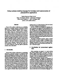
2 Process Managers Various approaches to managing the integration of IT systems have been developed such as distributed objects (CORBA), message brokers and Internet portals [Linthicum, 2001]. Recently, Web Services have appeared as a new approach to integrate IT systems through XML documents over Internet protocols [Oellermann, 2001]. However, with the exception of some recent developments of Web Services, such as BPEL4WS, these technologies mostly function as interfaces to existing IT systems and do not lend adequate support to the business processes. Therefore, a new type of process oriented integration architectures have been developed, referred to as process managers (sometimes business process management systems, process brokers, or process automation systems), which closely reflect the business processes (in healthcare: healthcare processes), see Figure 1 [Dayal et al, 2001; Linthicum, 2001; Johannesson el al, 2001].
heeaalltt H h hccaarree P proce sses
proce P ss m Maannaag geerr ((ee -pro cesse s) CO
IT- sy stem
RBA
IT-sys tem
Web servic es
IT- sys tem
IT-sys tem
Figure 1. The process manager may be viewed as a layer of abstraction above the IT systems. The process manager both visualises and manages the communication between the IT systems and human actors via e.g. desktop computers.
Somewhat simplified, the process manager functions as an extra abstraction layer (see the “process manager” layer in Figure 1) above the existing IT systems and integration technology, like Corba and Web Services [Linthicum, 2001]. The process manager is, hence, a software product that visualises and executes the communication between the IT systems and between the IT systems and the human actors. In this paper, we make a distinction between healthcare processes, application processes and e-processes, see Figure 2. This distinction facilitates the understanding of the process manager’s functionality and the relationship between the developed diagrams, described in Section 3. By healthcare process we mean a partial order of manual tasks, which are performed by human actors and based on (business) rules. Examples of manual tasks are “treating a patient”, or “using a computer”. Healthcare processes are complemented by business rules. An example of a business rule is that “patients have to pay in advance of the examination”. Another example is that “before a patient gets a new medicine the responsible physician must check which previous experiences the patient has with medication of the same type”. The application process comprises the set of actions (scripts) executed in the IT systems, and the logic determining how to react to events triggered by communication with human beings and other IT systems. The application processes, like healthcare processes, also include business rules, determined by the healthcare unit. The healthcare unit may also replace and automate business rules included in healthcare processes by using IT systems. This means that some of the business rules, which are the basis for manual tasks, can be transferred from the healthcare processes to the application processes. For instance, an IT system, instead of a human actor, could check the patient’s medical record in order to investigate the patient’s experiences of a certain drug. To understand an organisation in depth, both the business and application processes need to be modelled [Rayport et al, 1995, Steneskog, 1999], since both types of processes contain the organisation’s business rules. Steneskog [1999] states that we may need different modelling concepts and techniques when modelling business processes and application processes (“application processes” are called “virtual processes” in Steneskog’s terminology). Steneskog [1999] means that application processes are more difficult to identify, since they are hidden in the software code. Finally, by e-process we mean a certain type of application process, which is executed in a process manager. An e-process is essentially a series of message exchanges with the environment, comprising also the interaction logic that controls the communication with various IT systems and human beings, as well as those business rules that can be automated, see Figure 2.
health care p roces ses
e -pro cesse s ( ex ecute d in a proce ss ma nager application p roces ) se applic ation proce sses
s
applic ation proce sses
Figure 2. The distinctions between business processes performed by human actors, e-processes executed by the process managers, and application processes executed by other IT systems.
The benefits of a process manager are many. The communication between the IT systems and between the IT systems and the human actors may be changed at any time. This can be done by changing the eprocess, which is executed in the process manager. The process manager also contains specific tools for eprocess design and change. Since the process manager executes the graphical diagrams, it also facilitates monitoring the e-process. The process diagrams can then be used to study the state of the instances of a single patient process while it is running, e.g., to check the transfer of information concerning a particular treatment for the specific patient between two or more healthcare providers. It is also possible to let the process manager simulate process scenarios in order to come up with an optimal communication pattern. Much effort is presently spent on developing process manager technology. Some products that use this philosophy are Vitria Technology’s BusinessWare, IBM’s Websphare MQ Workflow , Microsoft’s Biztalk Server, and Visuera Integration AB’s Visuera Process Manager (PM). Furthermore, message brokers and application servers enhance their functionality with graphical process model management, to get closer to process manager functionality [Linthicum, 2001].
3 Method support for process managers In the Vita Nova projects, the Visuera Process Manager [Visuera, 2004] was used, together with a method in which Business Model Language (BML), a graphical process modelling language for modelling and executing e-processes. BML, was integrated with UML Activity diagrams, which describes the healthcare processes. Home care Patient
H Proim mearCy c are arhe he ealtahlthc careare pr proceocess sses es
Nurse
Expire Timer
Process manager
Start Timer
Wait for Event
register admission reply
Home care e- pro cesse s
End
A
IT System A -
IT System
IT System B
A IT System
B
Primary care Patient
Nurse PrHim om areyccare h are health ealthcare care proce processes sses
Physician Expire Timer
Process manager Prima ry- ca re e- p roces ses
IT System
Start Timer
Wait for Event
register admission reply
End
IT System C IT System D
C IT System
D
Figure 3. Healthcare processes (modelled using UML Activity diagram), e-process (modelled using BML) and integrated IT system in different swim lanes.
BML [Johannesson et al, 2001; Wåhlander et al, 2001 ] has similarities with Specification and Description Language (SDL), but is more adapted to IT systems integration. BML’s metamodel consists of a limited number of concepts; the main are: “receive message”, “send message”, “automated task”, “choice”, “start timer” and “timer expired”. In Visuera Process Manager, BML is used directly as an implementation language and replaces, to some extent, ordinary programming languages. UML Activity diagram s are used for modelling the healthcare processes. By adding swim lanes (in UML 2.0 called partitions) to the method, diagrams of different healthcare processes can be related, e.g, the patients’ process, nurses’ process and physicians’ process. In Figure 3, two different swim lane models, the home healthcare processes and the primary care healthcare processes, are specified. For each healthcare unit the different healthcare processes (patient, nurse and physician) are specified using UML Activity diagrams. These diagrams are related to each other and to the e-processes, represented as BML diagrams. The BML diagrams will be executed in the process manager. Finally, the e-processes are related to the IT system, which the e-process integrate. In Figure 3 the relations (i.e., message passing) between the healthcare processes, the e-processes and the IT systems are visualised as dotted lines. Note that IT system from different healthcare units also are integrated via the process manager (see A in Figure 3). The different IT systems’ application processes were not modelled in the Vita Nova projects. Such a task will probably be time consuming since experiences from the Vita Nova projects showed that a several existing IT system were poorly documented. However, a major idea in the Vita Nova projects was to transfer the business rules from the applications to the e-processes, which will create a flexible integration solution.
4 Design solutions In this section we present a number of design solutions, i.e., laboratory solutions which are not yet implemented in industry. However, they have been partially validated in the Process Broker and Vita Nova project. The design solutions are described by the following form: • Context – describe the situation/circumstances to situate the targeted interoperability problem • Problem – an explicit statement of the interoperability problem concerned • Solution – describe the implemented practice (proposed solution) to solve the problem defined • Strength – the strong point of the solution and its possible limitation 4.1 Value based process modelling Context Conceptual models have become important tools for designing and managing complex, distributed and heterogeneous systems, e.g. e-commerce and e-health [UN/CEFACT, 2003]. In e-commerce and e-health it is possible to identify two basic types of conceptual models: business models and process models. A business model focuses on the what in a system, identifying agents, resources, and exchanges of resources between agents. Thus, a business model provides a high-level view of the activities taking place in ecommerce and e-health. A process model, on the other hand, focuses on the how in an e-commerce or ehealth system, specifying operational and procedural aspects of business communication. The process model moves into a more detailed view on the choreography of the activities carried out by agents [Gordijn et al, 2000]. Problem In order to realize interoperability between services and systems, it is required to make their underlying processes interoperable. Designing and understanding the interrelationships between a numbers of complex interacting processes can be a difficult and time consuming task. Furthermore, it is often difficult to understand why a process model has been designed in a certain way and what consequences alternative designs would have.
Solution Process models should be given a declarative foundation by basing them on business models that describe the exchange of value. Two instruments for a declarative foundation of process models are process patterns and activity dependencies. A process pattern is a generic template for a set of interrelated activities between two agents, while an activity dependency expresses a sequential relationship between two activities [Bergholtz et al, 2004]. There exist many different kinds of patterns for business processes. These include basic workflow patterns [Aalst el at, 2003], transaction patterns as in ebXML [UN/CEFACT, 2003] and more complex patterns like the Action Workflow pattern [Winograd el at, 1986]. Such patterns provide a basis for a partial ordering of the activities taking place in a business process. However, the ordering derived from such process patterns only provide a starting point for designing complete business process diagrams, i.e., it needs to be complemented by additional interrelationships among the activities in the process diagram to be designed. These interrelationships should have a clear business motivation, i.e., every interrelationship between two activities should be explainable and motivated in business terms. We suggest formalizing this idea of business motivation by introducing the notion of activity dependencies. An activity dependency is a pair of activities, where the second activity for some reason is dependent on the first one. We identify four different kinds of activity dependencies, each one providing a particular reason expressed in business terms, for the interrelationship between the activities. Flow dependencies. A flow dependency [Malone et al, 1999] is a relationship between two activities, which expresses that the resources obtained by the first activity are required as input to the second activity. An example could be a retailer who has to obtain a product from an importer before delivering it to a customer. Another example could be that a healthcare unit needs to have a delivery of a certain resource type before a therapy could be performed. Trust dependencies. A trust dependency is a relationship between two activities, which expresses that the first activity has to be carried out before the other one as a consequence of low trust between the agents.
Informally, a trust dependency states that one agent wants to see the other agent do her work before doing his own work. An example could be a car dealer who requires a down payment from a customer before delivering a car. Another example could be that a patient’s insurance company has to pay the healthcare unit before a therapy could be performed.
Control dependencies. A control dependency exists when one agent wants information about another agent before establishing a contract with that agent. A typical example could be a company making a credit check on a potential customer. Another example could be that a healthcare unit needs to check with another unit about a patient’s status, before treating the patient. Negotiation dependencies. A negotiation dependency expresses that an agent is not prepared to establish a contract with another agent before she has established another contract with a third agent. One reason for this could be that an agent wants to ensure that certain resources can be procured before entering into a contract where these resources are required. Another reason could be that an agent does not want to procure certain resources before there is a contract for an activity where these resources are required. An example could be that a healthcare unit need to establish a contract with another healthcare unit before promising to perform a therapy. A business process diagram can be understood and designed based on process patterns and activity dependencies. Designing a business process diagram is not a trivial task but requires a large number of design decisions. In order to support a designer in this task, we propose an automated designers assistant that guides the designer through the task by means of a sequence of questions. The questions can be divided into four steps, see Figure 4. Step 1 during which the business model is established. The information gathered in this phase is about the agents involved in the business process, the resources exchanged between them, and the activities through which these resources are exchanged. The result from this step is a business model.
Step 2 during which information about the (partial) order between the activities is gathered. The result from this step is an ordering of the activities in the execution phase of a process model. Step 3 during which information about existing negotiation dependencies is gathered. The result from this step is an ordering of the activities in the negotiation phase of a process model. Step 4 during which the communicative acts needed to handle the activities are introduced and the (partial) order between them is established. The result from this step is an ordering of activities that crosses the negotiation and execution phases. Step 5 during which set of production rules needed to be applied on introduced patterns with respect to execution, negotiation and process orders.
Step 1
Step 2
Step 3
Step 4
Step 5
Business Model
Execution Order
Negotiation Order
Refined Order
ProcessModel
Q-A Session
Q-A Session
Q-A Session
Q-A Session
Auto Generation
Figure 4. Steps of the Designer Assistant Strength Process models that are given a declarative foundation based on business models would provide justifications, expressible in business terms, for design decisions made in process modelling, thereby facilitating communication between systems designers and business users. Following the layered approach of section 2 and 3, we have by introducing the value concept added a third level, the business model, describing the value foundation of the business. Graphically this can be viewed as in Figure 5.
busine ss mod els
health care p rocess es
e-proc esses IT -sy stem
CORBA
IT -sy s
tem
Web s ervice s IT -sy stem
IT -sy s
tem
Figure 5. A business model layer added above the healthcare processes. The business model provides justification to the design decisions made in process modelling. 4.2 View based process modelling Context Process diagrams have become an important tool for specifying and analysing the business processes and the e-processes, which are constructed to be executed in process managers. However, when integrating
different IT systems many different aspects need to be taken care of. For example, exception handling makes up a large part of an integration specification, i.e., the specification need to take into account different situations when IT systems do not respond in an expected way. The description of exceptions easily obscures the main business logic. Furthermore, it is possible to distinguish among several kinds of stakeholders involved in system integration projects: domain experts such as business managers, owners of external IT systems, business and technical designers, and operators that handle the day-to-day operations. Different stakeholders require different views of the integration specification, while at the same time they need to be able to communicate with each other using a common specification. Problem System integration specifications often results in highly unstructured and complex process diagrams, specifying the integration between the IT systems. These diagrams are also used by different stakeholders, which are only interested in viewing special parts of the diagrams. Solution Process diagrams visualizing the integration of systems should be structured through a series of views. These series of views should start with a customer oriented view, or some other actor’s view, on the business level and add more and more details moving from a business perspective to a more technical perspective [Johannesson et al, 2001]. The different views of process diagrams are described below and illustrated by means of a healthcare case, in which a patient wants to order an investigation. The order is send to an IT system, System A, which offers the patient date and time for the investigation and if the patient accept the date and time, update the order. However, if the patient does not pay tax in the county to which the healthcare unit belongs, a healthcare unit manager first has to accept the order.
Customer [Order answer]
[Order]
Customer process
Figure 6. Patient interaction (View 1) View 1. Patient interaction. This view models the interactions between the integrated system and the patient, i.e., the messages exchanged by the patient and the integrated system as well as the flow of control, see Fig 6. Note, Figure 6 (and 7) only visualise the process diagram from a static point view, i.e., the control flows are not visualised. Process diagrams visualising the control flows are described in [Johannesson et al, 2001]. Note that a patient could be a nurse, physician or any other healthcare provider, or a customer in another domain (therefore we use the term “customer” in the figures). View 2. System requests. This view is an extension of view 1 and describes how the integrated system produces the messages and sends them to the patient, i.e., answers the patient’s requests. Therefore, the designer must determine how the messages sent by the integrated system to the patient are to be produced, i.e., this view must also model the interaction with the IT systems and human being to be integrated. For every IT system and human being integrated, an interface process needs to be constructed, see the two process diagrams at the bottom of Figure 7. The design rule is: one interface process describes exactly one IT system’s or human actor’s interaction with the system. In the simplest case, only one system produces the message to the patient. In some cases, it is convenient to introduce two or more levels of sub processes. If the sub process to be specified requires interaction with several IT systems, the designer should construct a synchronization process, in the middle in Fig. 2, which invokes its own sub processes and synchronizes these. Following Figure 7, if the patient is not a tax payer
in the region, the synchronization process sends a message to both Interface process a and b. Interface process b sends a massage to the Manager, which has to accept the order or not.
Customer [Order answer] [Order]
Customer process [Order answer2] [Order2]
Synchronisation process [Manager answer]
[Update answer]
[Update] [Question manager]
Interface process b
Interface process a [Update answer2]
[Manager answer2] [Update2] [Question manager2] App A Manager
Figure 7. System request (view 2) View 3. Exception handling and resource releasing. First, this view specifies the exception handling. Views 1 and 2 specify only the normal course of events. In view 3, the process diagrams specify how to handle exceptions, i.e. situations where an external IT system or a human actor has not replied to a request within a pre-specified time limit. Secondly, this view describes resource releasing. When a process cannot be completed as intended, it becomes necessary to release the resources that have been reserved or booked during the process. View 4. Notifications. This view adds all notifications messages. We have identified three situations where notification messages are required. First, when an exception has occurred, it is customary to inform an operator about this event so that he or she may take appropriate action. Secondly, a notification about essential states of affairs may be sent to a maintenance process which redundantly stores the information. The need for such a maintenance process is described in Section 4.3. Thirdly, a notification can be sent to a data warehouse, which uses the information for strategic analysis and decision. Strength The views presented above can be used for two reasons. First, it could help the designer to construct the process diagrams. A designer could utilize the views by first constructing a process diagram according to view 1 and then gradually refining it until a set of diagrams in view 4 is obtained. Therefore, the views can be seen as steps in a method for designing process diagrams. Secondly, it can be used for presentation purposes to show or hide parts of process diagrams. Business oriented users can choose to see only the top view or views, while technical designers and implementers can proceed to the lower views. Even for the latter category of stakeholders, the layered views can help to understand a system by allowing the focus on an essential business perspective first and thereafter proceed to a technical perspective. Different categories of users, for example customers/healthcare providers, business and technical designers, have the possibility of suggesting input on the right level in the modelling process. Business designers probably want to concentrate on the important parts of the business processes to clarify how they want the main business logic to work. The views presented above may apply to the healthcare process as well as the eprocesses. 4.3. Master storage for process managers Context Integration of IT systems can be supported by many different architectures. One architecture for integrating IT systems is the point-to-point solution where every IT system is directly connected to every
other IT system, see Figure 8 (left). This solution could work for a small number of IT systems, but as the number of IT systems increases, the number of connections quickly becomes overwhelming. By using a central message broker, see Figure 8 (middle) or process manager, see Figure 8 (right), this complexity is reduced, i.e., the number of interfaces will be reduced, tools to facilitate the format conversions can be applied, and the visualisation added by the process manager enables different categories of people to take part in the process design.
IT system A
IT system A
IT system A
IT system B
IT system B IT system B
IT system C
Message Broker
Process Manager
IT system C Application IT system D A
IT system D
IT system C
Human Role
Figure 8. Point-to-point solution to the left, and many-to-many solutions in the middle (a massage broker) and to the right (a process manager). Problem Integration of IT systems is a complex task and it is seldom possible to integrate every IT system at one occasion. Therefore, integrated IT systems can still communicate with external systems, which are not part of the integrated solution. These IT systems can be updated without the message broker or process manager being notified. For example, information about a patient can be changed by mistake when an external system communicates with IT system connected to the integrated solution. Solution When integrating different IT system, for example by using a message broker or process manager, a master storage should be developed that duplicates part of the data in the integrated IT systems [Johannesson et al, 2001]. Strength There are several reasons for maintaining redundant information in a master storage. First, it is possible that the integrated IT system can be updated without the message broker or process manager being notified. By using an internal storage the system has complete and correct data saved in one place. Secondly, if the patient or customer service quickly requires information about, for example, an order, the system does not have to query several IT systems; it only has to query the master storage. It is not unusual that information about a patients or customer is distributed over several IT systems. In that case, the internal storage is from a performance perspective, an important improvement of a system. Thirdly, the opportunity to notify an internal storage of important events that occur in the system, makes it possible to create a data warehouse that is updated in real-time. A message broker or process manager can support data movement in real-time and it thereby can provide business managers with constantly new information, which can be aggregated.
5 Conclusions In section 1 we introduced the following issues that need to be addressed: Business Orientation, Traceability, and Information correctness. Business Orientation is about describing the business processes in business terms. This is addressed through both the value and view based process modelling. These design solutions focus on business oriented concepts like value, customer and provider, instead of going directly into procedural details. This allows a stakeholder to get a high level overview of the process expressed in familiar business terms.
Furthermore, when the stakeholder wants to get deeper into the details of the process she can use the views of the models to hide details irrelevant for her present purposes. Traceability is about understanding and tracking the reasons for design decisions in a process model. This is also addressed through the value based process modelling. Reasons for process design are based on value concepts complemented by action dependencies and process patterns. These allow a stakeholder to understand specific process designs in terms of higher level concepts, which also provides a basis for generating and comparing alternative designs, Information correctness is about maintaining a consistent and correct view of the information in the entire distributed system in spite of local autonomy. This problem is addressed by the master storage design solution, which offers an additional storage for ensuring information correctness. We believe that the proposed design solutions will provide important benefits for process modelling and managers, thereby strengthening one of the most promising approaches for interoperability. Further work will include the identification of additional process patterns as well as empirical validation in healthcare IT systems. Acknowledgement
The authors would like to thank all the VITA Nova project members. The VITA Nova – Hemma project is sponsored by the Vinnova (Swedish Agency for Innovation Systems) program for IT in home healthcare. The project is part of the joint research activities “Design principles for interoperability” (WP6) and “Enterprise interoperability architectures” (WP9) of the INTEROP Network of Excellence sponsored by EU.
References [Aalst et al, 2003] van der Aalst, W.M.P., ter Hofstede A.H.M., Kiepuszewski B., and Baros A.P.: Workflow Patterns”, Distributed and Parallell Databases, 14(3), July, 2003 [Bergholz et al, 2004] Bergholz, M.. Jayaweera, P., Johannesson, P., Wohed, P.: A pattern and dependency based approach to the design of process models, accepted at ER 2004, Shanghai, China, 2004
[Dayal et al, 2001] Dayal U., Hsu M., Ladin R.: Business Process Coordination: State of the Art, Trends, and Open Issues, In: Proceedings of the 27th International Conference on Very Large Data Bases, September 11-14, Roma, Italy, pp. 3-13, 2001
[Gordijn et al, 2000] Gordijn, J., Akkerman J.M. and Vliet J.C.,: Business Modelling, is not Process Modelling, Proc. of the 1th International workshop on Conceptual Modeling Approaches for eBusiness (eCOMO’2000) (2000) [Haux et al, 2004] Haux R., Winter A., Ammenwerth E., Birgl B., Strategic Information Management i Hospoitals. An introduction to Hospital Information Systems, Health Informatics Series, Springer, 2004 [Johannesson et al, 2001] Johannesson P., Perjons E.: Design principles for process modelling languages in enterprise application integration, Information System, 26, pp. 165-184, 2001 [Linthicum, 2001] Linthicum, S. D.: B2B Application Integration – e-Business-Enable Your Enterprise, AddisonWesley, 2001 [Malone et al, 1999] Malone, T., Crowston, K., Lee J., Pentland, B., Dellarocas C., Wyner, G., Quimby, J., Osborn, C., Bernstein, A., Herman, G., Klein, M., and O´Donnell, E. (1999), “Towards a Handbook of Organisational Processes”, Management Science, Vol 45, No 3, pp. 425-443. [McCarthy, 1992] McCarthy, W.E.: The REA Accounting Model: A Generalized Framework for Accounting Systems in Shared Data Environment, The Accounting Review (1992)
[Oellerman, 2001] Oellermann W. L.:Architecting Web Services, Apress, 2001 [Perjons et al, 2004] Perjons E., Wangler B., Wäyrynen J., Åhlfeldt R.-M.: "Introducing a Process Manager in Healthcare. An experience report", In: Proceedings of The Ninth International Symposium on Health Information Management Research (ISHiMR), Sheffield, June 15 – 17, 2004 [Steneskog, 1999] Steneskog G.: Business Process Models Revised: Challanging the Physical Metaphor, in Nilsson A. G., Tolis C., Nellborn C. (eds): Perpectives on Business Modelling, Springer-Verlag, 1999 [Rayport et al, 1995] Rayport J.F., Svikola J.J: Exploiting the Virtual Value Chain, Harvard Business Review, Nov-Dec, 1995 [UN/CEFACT, 2003] UN/CEFACT Modelling Methodology (UMM), Revision 10, available at (2003-0404) http://www.untmg.org/doc_bpwg.html (2003) [Vissers, 1998] Vissers, J. M. H.: Health care management modelling: a process perspective, Health Care Management Science, 1, pp. 77-85, 1998 [Visuera, 2004] Visuera Process Manager, Visuera Integration AB, [online] http://www.visuera.com [accessed Jan 2004] [Wangler et al, 2003] Wangler B., Åhlfeldt R.-M., Perjons E.: Process oriented information systems architectures in healthcare, Health Informatics Journal, Vol 9(4), pp. 253-265, 2003 [Winograd et al, 1986] Winograd, T., and Flores, F.: Understanding Computers and Cognition: A New Foundation for design, Ablex, Norwood, N.J. (1986)
[Wåhlander, et al, 2001] Wåhlander, C., Nilsson, M., Törnebohm, J., 2001. Visuera Process Manager.Visuera Integration AB.