Designing and implementing an Spatial Augmented Reality X-Ray Fábio R. de Miranda1 Romero Tori1 Cláudio E. S. Bueno1 Lucas P. Trias1
Abstract:
Casting digital-controlled light over real object surfaces, thus creating new textures and special effects, brings to designers and engineers an endless spectrum of possibilities and innovation for their projects. This technology, called Spatial Augmented Reality, can be considered as a kind of "virtual material" that can be manipulated by designers in augmented environments. In order to achieve more knowledge on the use of this technology, we have developed AR X-Ray, a spatial augmented reality tool. Through the use of a portable projector a Virtual X-Ray is emitted over real walls, allowing visual exploration of internal details of buildings (such as pipes and ducts). This paper presents the design, implementaion and results of this project. Some details regarding solutions for technical problems are also discussed, as following: projector tracking, proper registration of synthetic information over real objects and the development of a shader that manipulates the transparency of textures to allow the user to view what is behind objects.
1 Centro Universitário Senac. LPAI - Laboratório de Pesquisa em Ambientes Interativos, Av. Eng. Eusébio Stevaux, 823 São Paulo – SP {fabio.rmiranda, romero.tori, cesbueno}@sp.senac.br,
[email protected]
AR X-Ray: Portable Projector-Based Augmented Exploration of Buildings
1
Introduction
Spatial Augmented Reality (SAR) [1] has great potential for applications that require augmentation of the real space without forcing the user to wear goggles or any other uncomfortable equipment. Among several ways of creating spatial augmentation, the use of projectors to paint “light textures” onto physical objects is one of the most promising. Works such as those of Raskar et. al [2] and Pinhanez [3] demonstrated the viability of projectorbased augmented reality as well as some interesting ideas for applications. Although having some limitations, as the need of appropriate illumination, adequate reflectance property of the surfaces receiving the projections and user tracking if the projection represents 3D perspectives instead of simple 2d textures, this technique can still be used in a vast amount of innovative SAR applications. “AR X-Ray”, an interactive projector-based spatial-augmented tool for visual exploration of architectonic structures, is one of these solutions. With “AR XRay” it is possible to virtually explore internal layers of real walls by moving a projector and controlling the depth of a virtual ray that projects internal layers of the structure directly over its surface, producing an effect that resembles an x-ray vision (Fig. 1).
Figure 1. User holds a projector-camera system that delivers the augmentation with proper registration This project met some challenges related with registration, tracking, real-time texture manipulation and interface design. In this paper we show how those difficulties were solved and present the first complete functional prototype, its architecture, some initial tests results
48
RITA • Volume XV • Número 3 • 2008
AR X-Ray: Portable Projector-based Augmented Exploration of Buildings
and next steps. The main contributions of this work are: an innovative use of projectorbased augmented reality to produce a virtual x-ray tool that frees the user of wearing special devices; the demonstration of a low-cost alternative for the 3D tracking of a mobile projector; the registration of 3D geometry over real objects in a mobile projector through a projective transformation; the development of a prototype as a proof of concept and the documentation of implementation aspects involved in doing it; a "testbed” for further experiments and studies on interface design of interactive spatial augmented applications. This article is organized as follows: in section 2 we review relevant previous work related to this project, in section 3 the project is explained in detail to include some of its design goals and implementation techniques, in section 4 the results obtained are presented. The conclusions of this work are presented in section 5 and future work is detailed in section 6.
2
Related work
2.1 Projector-based augmented reality The most important technology behind this project is known as spatial augmented reality, more specifically the one based on the use of projectors casting images directly over the surfaces of real objects. Bimber and Raskar [1] present some pioneer projects in this area. Among these Shader Lamps [2] and “Being There” [4] were responsible for inspiring us to develop AR X-ray. The idea of “Shader Lamps” is to project 2D textures onto the surfaces of real objects. These objects need to have preferably homogeneous white surfaces. The method developed is sufficiently general to address any kind of rigid 3D surfaces, using one or more casually aligned projectors. The authors of “Shader Lamps” also have developed techniques for tracking users and projectors through the use of magnetic trackers. “Being There” is another example of spatial augmented reality based on projectors. This project constructed a human-size environment composed of walls made of Styrofoam blocks. Textures of bricks, wood and even transparent windows are projected over these walls creating a convincing environment in which the user can walk-through. Since the viewer position is tracked it is possible to look outside or see the next room through virtual windows. 2.2 Handheld projectors The imminent widespread commercial availability of mobile, lightweight projectors either in standalone form or integrated in other devices such as cell phones makes them a promising platform for mobile applications in entertainment, multimedia and support of collaborative work. A pioneering work that showcased the possibilities of mobile projectors was iLamps [5], in which a user carries a projector-camera system that was made location-aware through
RITA • Volume XV • Número 3 • 2008
49
AR X-Ray: Portable Projector-Based Augmented Exploration of Buildings
the usage of fiducial markers in environmental objects that allowed the system to display contextual information and emulate mouse-like interactions by moving the projector in relation to the fiducials. In iLamps the registration between projectors and augmented objects was solved by homographies (plane-to-plane mappings between projector image coordinates and surfaces projected on). Recently, the VisiCon project [6] demonstrated the use of handheld projectors in the context of a multiplayer game where players control a real robot on the floor that senses commands embedded in the projector light through photosensors on its back. VisiCon explores accelerometers to compute the inclination of the projector based on the direction of gravity and transform the projected image so that it remains rectangular as the user moves it. The work by Dao et al [7] recently demonstrated the use of tilt sensors and 3D digital compasses to allow the user to move the projector and still keep the projected image rectangular on flat surfaces. Interaction paradigms for mobile projectors have been explored in the work by Cao et. al [8] where a projector was tracked in 3D-space with the goal of revealing more content of a bigger virtual screen accordingly, a paradigm the authors call flashlight metaphor and that bears similarity to our work, the biggest difference is that in AR X-Ray registration matches a 3D model with its real counterpart, and not a virtual screen. The work of Blask et al [9] focused on interaction paradigms and used a technique similar to the flashlight where movement parallel to the projection screen was used to pan an image and movement perpendicular to it could zoom in and out. That work used a common projector and motion tracking devices at the wrists of users to simulate a wristwatch projector. As real mobile handheld projectors are just beginning to hit the market with offers from manufactures such as Siemens, Mitsubishi and Toshiba, such devices are still basically miniatures of conventional meeting room projectors and lack many of the features that would be essential to support most of the interactive applications currently proposed by the research community. Thus it is common to do protopyping by augmenting the current projectors with cameras and extra sensors (such as motion and position trackers, for instance) and assume that future projectors will have those features. 2.3 Interactive Tools for Virtual X-Ray Vision This project intended to develop a set of tools for giving users the impression of seeing through solid objects [10]. As stated by the authors of that project they “consider x-ray vision to be the act of visualizing some target through at least one layer of occluding structure”. Their approach differs from ours as they use video see-through solution instead of spatial augmented reality. Based on a tracked user this project offers three main tools: Tunnel Tool, Room Selector Tool, Room in Miniature Tool and Room Slicer Tool. The Tunnel Tool is a “Frustum extending from the user’s position out along the direction of view”, creating the effect of looking through a virtual tunnel that cuts and penetrates the objects and walls. This approach is similar to that adopted in our project. The Room Selector Tool allows the user to control a 3D cursor along the direction of view for selecting rooms inside the real
50
RITA • Volume XV • Número 3 • 2008
AR X-Ray: Portable Projector-based Augmented Exploration of Buildings
environment. A selected room is shown from the user’s viewpoint with walls that would occlude the selected room shown in wireframe, and the user can control which objects inside the selected room will be shown by grouping them in layers. The Room in Miniature Tool is a third person view of a selected room. Finally, the Room Slicer Tool works in conjunction with the Room in Miniature Tool, allowing a third person exploration sliced planes of the room. 2.4 X-Ray Window This tool, presented in White et al [11] is a prototype developed at NASA’s Johnson Space Center aimed at giving crewmembers of International Space Station (ISS) a kind of X-Ray vision. Wearing special augmented reality glasses the user can "see through" the walls of the module or through the station. The main problem in this project is to select, convert, and combine information from various databases. 2.5 Augmented reality in architectural applications Presented in Webster et al. [12], this early work bears strong similarities with the purpose of AR X-Ray, though based on rather different implementation details. It demonstrated the visualization of structural elements registered over the real parts of buildings with a Head Mounted Device tracked by ultrasonic sensors. It can be considered an initial attempt at XRay vision since structural details could be visualized in wireframe (such as beams inside walls or ceilings and walls behind furniture, for instance). 2.6 Toolglass and magic lenses This early work [13] dealt with several issues related to see-through user interfaces in the context of traditional desktop applications. One of the ideas proposed in this work was that of a Magic Lens – a kind of semitransparent widget manipulated by the user with his hand or a second mouse cursor – that was able to reveal contextual information and suppress some details while enhancing others related to objects that are seen through it. 2.7 Using AR to Visualise Architecture Designs in an Outdoor Environment This work, presented in Thomas et al [14] is worth mentioning because it is an application of augmented reality to architecture. It presented ways of visualizing outdoor modifications or extensions to buildings through the use of a HMD. This is an early work and tracking was based on a digital compass and low-precision GPS that counted on the user proactively indicating his position or moving his head to compensate for registration errors.
RITA • Volume XV • Número 3 • 2008
51
AR X-Ray: Portable Projector-Based Augmented Exploration of Buildings
3
The AR X-Ray project
3.1 General vision The main goal of the AR X-Ray prototype, which is illustrated in Figure 1, is allowing the users move a handheld projector freely and visualize internal details of walls and buildings. The user should also be able to control through an interface the power of the simulated XRay vision, thus revealing inner details of walls or even seeing through them. The medium-term objective of this project is to create an innovative spatial augmented reality infrastructure, based on projections over real walls, in order to allow the visualization of internal structures in a way that simulates an idealized portable X-ray tool. This infrastructure is intended for future use as a platform for testing new interaction design approaches in spatial augmented reality as well as experiments on new applications like education, art and entertainment. The first problem faced by researchers working on augmenting reality tools aimed to give users some kind of “viewing-inside-and/or-through-objects” power is the “Superman’s X-Ray Vision” problem. This problem is related with the paradox of showing too much information about occluded structures, and getting the user confused, against the option of showing only the targeted information, and thus depriving the user of important visual depth and orientation references [15]. In our “Virtual X-Ray” this problem was solved by making the user manipulate a virtual “cutting tool” that simulated the penetration of a visualization “frustum” on the object, producing similar results as if the object was itself rendered in computer graphics and all the action was taking place in a computer graphics environment. Some design alternatives of interaction and visualization, as well as new applications of this technological infrastructure, will be studied as a second part of this project, whose focus will be on design issues. A known problem with immersive augmented reality, like that provided by optical or video see-through approach, is the difficulty for users to have correct distance perception in immersive virtual environments [16][17][18]. Other problems related with see-through displays are insufficient brightness, resolution and field of view, besides fatigue and strain [19]. Our X-ray approach avoids these problems by using spatial augmented reality and thus eliminating the need of goggles or other types of potentially cumbersome immersive apparatus.
52
RITA • Volume XV • Número 3 • 2008
AR X-Ray: Portable Projector-based Augmented Exploration of Buildings
Figure 2. Projector-camera system used in AR X-Ray AR X-Ray is conceived to be used with mobile projector-camera system with some form of input interface is available. In a way similar to [5][6][7][8], this work used a common projector with appended apparatus in order to simulate a mobile intelligent projector. The projector used in AR X-Ray can be seen in Figure 2, it is a Benq MP611 with a 800x600 resolution and 2400 ANSI lumens. It was incremented with a 640x480 webcam rigidly attached to it and a Nintendo Wii controller to be used as user input. Currently it needs to be tethered to a computer equipped with a GPU (graphics processing unit) through VGA and USB cables and also needs to be plugged to an AC power outlet, such tethers limit the range where the tool can be used but does not compromise the overall prototyping work. This work follows the basic idea of Shader Lamps [2] that was based on maintaining in software an augmented 3D representation of the real scene and projecting in such a way that the rendered images of the virtual objects match their real counterparts. In this approach, in order to augment a real object one has to augment the corresponding object in the virtual scene and register the projection so that real and virtual objects match. This is done through the use of properly positioned ARTag [19] markers and one webcam attached to the projector, and will be discussed further. 3.2 Application architecture
Application modules The AR X-Ray system can be seen in a general level as a system that converts the position of the projector and the desired zoom level into a rendering of the internal structure of objects that is superimposed on such real objects with the help of a projector. It was developed in Java and C and is comprised of modules specifically suited to tracking, interaction, calibration, registration, scene management (in Java3D) and composition of textures.
RITA • Volume XV • Número 3 • 2008
53
AR X-Ray: Portable Projector-Based Augmented Exploration of Buildings
Tracking (calibrated projectorcamera system and ARTag)
user input
Interaction Positioning of projector, buttons pressed
Model-view and projection matrices
zoom action,zoom level, focus
Java3D scene graph
image to be projected
position of holes, depth
X-Ray Application
Appearance control (GLSL shaders)
Figure 3: AR X-Ray Software Modules The tracking module is responsible for determining the position of the projector in space and is based on ARTag. This module is coded in C and is able to estimate the position of the projector in relation to a set of fiducial markers and sends such estimate to the main application (which runs the scene graph) through sockets. The Java 3D Scene Graph module outputs model-view and projection matrices (according to the same nomenclature used in OpenGL) so that a virtual camera can be positioned in a way the resulting synthesized images get correctly registered. The choice of Java3D for this module was due to the previous experience of the group with it and the perspective of reusing animation and interaction code available in some of its libraries. The interaction module allows the user to control the radius and depth of the hole that is seen on surfaces. This is done through an Wii controller attached to the project whose buttons number one and two are mapped to mouse keys via the GlovePIE utility [20]. The module responsible for appearance control changes the transparency of 3D models through the use of a pixel shader, and the Java3D scene graph is the major integrator that depends on all other modules in order to produce the image to be projected, and will be further detailed in subsection 3.3.3. 3.3 Technical problems
Registration and projection calibration Registration is the most important problem that must be overcome when devising an application aimed at enhancing real objects with synthetic augmentations that must match
54
RITA • Volume XV • Número 3 • 2008
AR X-Ray: Portable Projector-based Augmented Exploration of Buildings
their geometry well enough to give the users the perception that such augmentations are part of the real object. Our approach is based on the one that was outlined in [2] but is adapted to use a mobile projector, though the basic math is the same. The projector is seen as the dual of camera: instead of light rays coming from real objects through an optical center and inciding on a projection plane, the light rays are seen as being emitted by the projection plane and passing through an optical center before inciding on the real object. From the modeling standpoint, the main advantage of the projector operating as the dual of a camera is that the same well known techniques that can be used to estimate the parameters relevant to how an image forms in a camera can be used to represent the optics of the projector - for a thorough explanation of this image formation process, we recommend the work of Faugeras [21]. These parameters are represented in equations (I) and (II) – equation (I) shows that the points in image plane represented by mi (in homogeneous coordinates) are the result of the transformation of the 3D points Mi by a perspective projection matrix. (I)
Where mi and Mi are.
(II)
Some of the parameters in the projection matrix are called extrinsic camera parameters, and are related to the transformation of position in world coordinates between the camera or projector and a reference frame, such parameters are comprised of three angles that characterize the rotation of a camera around world axes and a translation vector, represented by r1, r2, r3 and tx, ty and tz in equation (II). The elements r1, r2, and r3 are each one a row vector that when stacked result in a common 3D-rotation matrix such as the one used commonly in graphical APIs such as OpenGL or Java3D, and tx, ty and tz are scalar values. The remaining parameters are intrinsic camera or projector parameters, because they determine changes in the image formation plane and are the same regardless of the camera position or orientation in space. These parameters are the position of the image plane center
RITA • Volume XV • Número 3 • 2008
55
AR X-Ray: Portable Projector-Based Augmented Exploration of Buildings
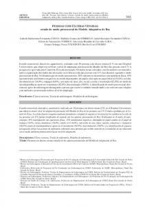
and that are related to the size of the focal of coordinates ( , ) and the parameters distance and the size (in continuous values) of the pixels in the image forming sensor. These parameters are related to the focal distance (the distance from the optical center to the and . plane where the image is formed) through the relations We can conclude then that in order to properly register through projection a point in image plane mi over its corresponding 3D point Mi it is necessary to know 11 parameters, of which 6 are extrinsic and 5 are intrinsic. In this procedure, we are mostly interested in the intrinsic parameters for the extrinsic will be later supplied by tracking the projector. This is a difference between our work and the original Shaderlamps [2] work because the latter estimated the full projection matrix since the projector would be kept immobile and the extrinsic parameters would not change. In AR X-Ray, a small utility was built to allow the determination of pairs of correspondences between 3D points in world coordinates Mi and their respective image points mi. Such utility allows the user to move a crosshair in image plane until it corresponds to a number of given known points in a calibration board. Such utility can be seen in Figure 4. After 3 sets of 37 correspondences are determined, a free implementation [22] of Zhang’s camera calibration algorithm [23] is used to estimate the intrinsic parameters (and extrinsic also, but those were discarded because they change when the projector moves). Once the intrinsic parameters of the projector are known, tracking is used to determine its extrinsic parameters and compose the proper projection matrix that will achieve correct registration.
Figure 4. Correspondences between images in projector image coordinates and real world coordinates used in projector calibration Tracking Tracking is fundamental in the AR X-Ray application to allow the system to project the proper augmentation images over real objects. Usually in projector-based applications when tracking is needed commercial magnetic [2] or infrared optical trackers [8] are used. Such types of tracking have good precision and are relatively immune to interferences of projection (such as the projector light), but are usually costly. We decided to investigate a more affordable alternative.
56
RITA • Volume XV • Número 3 • 2008
AR X-Ray: Portable Projector-based Augmented Exploration of Buildings
The most common kind of tracking employed in augmented reality is fiducial marker tracking, made very popular by ARToolkit. Despite its popularity, ARToolkit has a series of known shortcomings, such as low robustness due to occlusion of markers, instability of tracked poses, sensitivity to variations of illumination, and a steep increase in computational cost as the number of markers one wishes to track grows. In order to address such shortcomings, the AR research community proposed two tracking libraries that feature ID-based tracking and more robust feature detection, immunity to occlusion and lighting variation and pose tracking algorithms, ARTag [24] and ARToolkitPlus [25]. We chose ARTag for this project because it operated exceptionally under moderate occlusion and both in dark environments as well as in front of projector light too, this is illustrated in Figure 5, where a standard ARTag demo exhibits successful registration even when markers are lit by a projected texture. Such result is known and documented in literature [26][27].
Figure 5. Successful ARTag registration with markers in front of projected light as seen by webcam ARTag is more robust than ARToolkit, but it still exhibits some oscillation and instability in pose tracking for single markers. In order to circumvent this problem one is advised to use multi-markers, a resource that allows the programmer to use a series of markers and describe the known spatial transformations between them to the system. This allows the overall pose to be computed by an optimization procedure that takes into account all markers that are seen by the camera and their positions, and also allows the pose estimation to work even if some markers are not seen. In AR X-Ray, one goal was to allow the user to move the projector with some freedom inside our laboratory. One problem that needed to be solved was that the field of view and resolution of the webcam only allowed it to track reliably up until a distance of
RITA • Volume XV • Número 3 • 2008
57
AR X-Ray: Portable Projector-Based Augmented Exploration of Buildings
about 1.5 meters from the wall, as the user got further, the markers (that had around 10 centimeters) were no longer detectable.
Mkr10cluster02
Mkr30cluster02
Mkr03cluster01 Mkr01cluster01 Mkr02cluster01 Mkr20cluster02
Figure 6. Exploded view of 3D content to be registered over real building This problem was solved with an approach first described in a proposal to use ARTag in spacecraft docking [19], in which markers of variable size are used to compose several multi-marker detectors. Larger markers are used when the camera is further and as it approaches sets of smaller markers that can allow a finer positioning, the larger markers are ignored. In our system the placement of the sets of markers are indicated in the 3D model that represents the scene to represent where the markers are in respect to the scene. A schematic view of such model (where layers of walls are exploded to allow a better visualization) is presented in Figure 6. This model is exported as a VRML file and objects that have names of the form MkrXXclusterYY (where XX is the ARTag ID of the marker and YY indicates the multi-marker set it belongs to) are not treated as common scene objects, instead they are understood as markers and a multi-marker file that can be understood by ARTag describing them is created. The same markers can be seen in Figure 7, where (a), (b) and (c) are markers that allow the detection from larger distances and (d), (e) and (f) are bigger resolution multi-markers. It is worth noticing that currently the available ARTag implementation only allows for the creation of multi-marker sets that are planar. Some markers depicted in Figures 6 and 7 had to be split into more than one set. For instance, the multi-marker set specifiend in the scene file as cluster 02, comprised of the markers labelled as (a), (b) and (c) had to be split
58
RITA • Volume XV • Número 3 • 2008
AR X-Ray: Portable Projector-based Augmented Exploration of Buildings
into a multi-marker set that contained the coplanar markers (b) and (c) which was then joined by an individual marker (a).
(a)
(b) (d)
(e)
(f) (c)
Figure 7. ARTag markers of different sizes to allow proper tracking at different distances Ideally multi-marker setups should be placed with a small error between individual fiducials, usually one large object (such as poster or a board) is printed with all the markers fixed, thus assuring proper low error levels and avoiding compromising the detection. In AR X-Ray, it was unpractical to print all markers in a single board or sheet due to the dimensions involved (a sheet of approximately 9 m2 would be necessary) and it would occlude the objects to be augmented. Due to these factors, the placement of markers in the physical world was made with the help of a simple application that used ARTag and a webcam that displayed interactively the transformation of a marker being placed in relation to a reference marker and what the goal transformation was based on the data that came from the 3D content file. Another alternative that we used was printing markers on several A3 sheets and then putting them side-by-side. One step that is necessary to achieve good precision when tracking fiducial markers is the calibration of the camera to find its intrinsic parameters. Fortunately it is a more automatic process than calibrating the projector, in our project this was done using the GML Camera Calibration Toolbox [28]. Such toolboxes takes as an input several pictures of a chessboard with known square sizes and estimates intrinsic and extrinsic camera parameters. The process of estimating the projector position given an image of the scene in our project can be summarized as follows:
RITA • Volume XV • Número 3 • 2008
59
AR X-Ray: Portable Projector-Based Augmented Exploration of Buildings
i.
Find out all markers visible at the scene via their ARTag IDs
ii.
Discover the highest-precision set of markers that is visible (this varies with distance, if the user is closer, the smallest markers will be used)
iii.
Use ARTag to obtain the transformation between marker set and camera (this transformation is in camera coordinates). The coordinates of the projector in the camera frame is known by design, since they are rigidly attached to each other
iv.
Use the inverse of the transformation obtained in (iii) to convert the projector coordinates to marker coordinates
v.
Use the information of the VRML file to convert the marker coordinates to room coordinates and thus obtain the extrinsic parameters of the projector
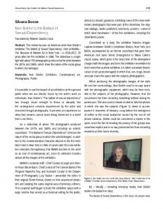
This process can be clarified by studying Figure 8, that shows a Spatial Relationship Graph (SRG) of our application. A Spatial Relationship Graph [30], like a scene graph, is able to represent the several objects and coordinate frames involved in a 3D application and the transformations between them. The major diference between a SRG and a regular scene graph is that in the former more than one edge is allowed between two nodes, meaning that the transformation between two objects can be derived from more than one source of information. A SRG is particularly suitable for augmented reality and tracking applications because often a situation is found where more than one mechanism contributes to the estimation of the position of an object or the relative transformation between coordinate frames that are relevant to the application. The SRG represented in Figure 8 shows the four reference frames that are important to AR X-Ray: real world, AR markers, a camera and a projector. Ultimately what we need to know is the transformation between the mobile projector and the real world, represented at the figure as Tprojector_world, but since such transformation is not directly available, it must be indirectly computed by means of other available information (dashed lines represent transformations inferred indirectly). In Figure 8, the Tmarkers_world transformation is one of the most straightforward to determine, since it is defined when the user places the markers in the real world. This Tmarkers_world transformation must be the same one indicated through marker clusters in the VRML file containing the scene, such result is achieved simply by putting markers in the scene, if there is an error in doing so, they can be easily relocated. The transformation represented by Tmarkers_cam represents where a given set o markers are in camera coordinates, and is derived from the best marker set that is visible by the webcam at a given moment. In order to know the position of the camera in relation to the markers, we need the inverse o Tmarkers_cam, named Tcam_markers and represented as a dashed line in Figure 8. This inversion must take into account that Tmarkers_cam is an affine transformation matrix representing change of coordinate systems. If a numerical inversion intended for a generic matrix is done, instabilities in pose estimation can arise.
60
RITA • Volume XV • Número 3 • 2008
AR X-Ray: Portable Projector-based Augmented Exploration of Buildings
The last transformation in the graph that remains to be determine is Tproj_cam, which relates the projector and camera coordinate systems (with the camera being attached to the projector). This transformation can be measured directly if there is any kind of mounting rig available that allows the direct measurement of such transformation or the system being used is a commercial projector-camera system. Since in this work we didn’t have such mounting rigs and attached the camera directly to the projector using adhesive tape (as can be seen in Figure 2), the procedure used to determine the relative position of the projector and camera was calibrating them once using the same chessboard pattern and use the extrinsic parameters of both to infer Tproj_cam.
Figure 8. Spatial relationship graph of the transformations involved in the AR X-Ray project Java3D scene graph Java3D is a scene graph based application programming interface (API), and defining such a graph is a significant part of application development, since the main transformations and relations are encoded in it. AR X-Ray’s scene graph is represented in Fig. 9, and as usual there is a common division in a viewing branch and another branch where most of geometry content (the models of walls’ layers, in our case), is kept. The geometry content is below the box called Content BranchGroup in the figure, and also holds the set of objects that is responsible for the X-ray effect, by triggering the shaders
RITA • Volume XV • Número 3 • 2008
61
AR X-Ray: Portable Projector-Based Augmented Exploration of Buildings
that run on the GPU through the use of special ShaderAppearance nodes that hold references to the scene geometry (represented by its subclass HoleAppearance in the scene graph). Virtual Universe (scene graph root)
Content branchGroup (root of the scene loaded from VRML file)
Viewing branchgroup (projection transform)
TransformGroup
(model-view transformation) Hole (effect of transparency – fragment shader) MultiHoleWall
Wall layer Shape3D
HolesContainer
...
Wall layer Shape3D
HoleController HoleAppearance
Figure 9. Scene graph of the X-Ray application In our application the 3D models were authored in modelling packages and exported as VRML files (a format that is very well supported under 3D APIs and authoring tools alike and that is able to store materials, texture and animations). One problem that we faced is that there is no way to link shaders to geometry in VRML, and a workaround had to be adopted by the application during content loading time. Such workaround consisted in scanning the scene graph that is being formed as the VRML files are loaded, and replacing any regular Java3D’s Apperance graph nodes by our custom HoleAppearance nodes. Each layer of wall (visible in Fig. 10) is represented as a distinct Shape 3D. Each HoleAppearance is associated with a specific layer of geometry and all the holes in a given scene area controlled by a HoleController class, which is the interface between the user events and the scene graph and holes position and radius processing. The geometry content is below the box called Content BranchGroup in the figure, and also holds the set of objects that is responsible for the X-ray effect, by triggering the shaders that run on the GPU through the use of special ShaderAppearance nodes that hold references to the scene geometry (represented by its subclass HoleAppearance in the scene graph).
62
RITA • Volume XV • Número 3 • 2008
AR X-Ray: Portable Projector-based Augmented Exploration of Buildings
Figure 10. XRay Shader applied to layers of internal details of a wall During the first registration tests of the system, it became clear that the outermost layer of the wall, with the superficial details (seen in Fig. 10), didn’t need to be present in the 3D model. This layer contains details that are already visible at the real wall, and as such didn’t need to be projected, and also when present it revealed minor inconsistencies in registration and 3D model authoring that were distracting to users and didn’t contribute to the objective of AR X-Ray that ultimately is study applications and forms of interactions. In order to avoid this problem, when the system is being used a black matte is added on top of the scene geometry in a way that only the internal details of the walls get projected (see Fig. 11).
Figure 11. A black matte (left) used to avoid reprojecting onto the wall its own superficial details, revealing only internal objects
RITA • Volume XV • Número 3 • 2008
63
AR X-Ray: Portable Projector-Based Augmented Exploration of Buildings
X-Ray shaders The goal of this project is devising an application that can be used to show to the user the internal structure of objects such as a wall, in our case. After the registration process, the user points at positions in a multi-layer wall and is then presented by the augmenting elements that reveal the innards of the wall, thus giving the user an experience that resembles drilling through several layers of wall, varying the depth at his will and controlling the radius of the holes being dug are desired functionalities for the application. The application was built in such a way that the frontmost layers of geometry have holes of larger sizes, as can be seen in Fig. 10. The first approach tried in order to obtain the desired X-Ray effect was to use the texture of the 3D models as a canvas where the holes could be drawn in the alpha channel of such textures. This is a technique that was very fast to implement, with the problems to solve being only the necessity of converting an intersection point obtained between the 3D mesh representing the wall and a pick ray controlled by the user from 3D coordinates into texture coordinates (in pixels). Once this is done, the following step was drawing the intended holes at the texture’s alpha channel.
Figure 12. Variation of parameters that determine the hole shader
64
RITA • Volume XV • Número 3 • 2008
AR X-Ray: Portable Projector-based Augmented Exploration of Buildings
However, the performance of the prototypes was very unsatisfactory in our test system (a 3.2 GHz Pentium 4 CPU with GeForce 6600 GT acceleration card). When using texture images with a resolution that provided a photorealistic effect, the time spent to refresh the screen lead the user to miss the sensation of interactivity. We believe that this is due to (i) the relatively slow operation of iterating through a high resolution image and (ii) inefficiencies in Java3D that sometimes implied in round the tripping whole texture between the graphics card and our application once per frame – we were unable to obtain reference to a texture stored in graphics memory. Such implementation bottlenecks are becoming increasingly less relevant as new and more efficient image I/O and referencing techniques are adopted as Java3D progresses and the underlying Java OpenGL layer it uses becomes more accessible (we used versions 1.4 through 1.5.3 in our tests). Considering that the system must be highly interactive to give the user the impression of perfurating the wall, this low performance was an unacceptable problem. Moreover, all the processing of the coordinates of texture and image, picking of pointer position and the changes in the alpha channel of the image are made at the central processing unit, what turns it in a bottleneck in the system. In order to decentralize the processing, the graphics processing unit (GPU) was used instead of the CPU to draw the hole in the alpha channel. This was done through the use of a fragment, or shader program, which is a routine or piece of code that is compiled in the application startup and executed directly on the graphics processor. A fragment shader executes once for every pixel of the rendered image, in real-time, and offloads processing burden from the CPU helping us assure interactive rates. The shader that was developed was implemented in OpenGL Shading Language (GLSL) language, and accepted as parameters the variables radius, position, attenuation zone and target alpha. In Fig. 12 it is possible to see the variation of the parameters that control the shader – in the center it is possible to see a set of default parameters – a default radius is used, the hole is drawn at the center of the texture coordinates, the alpha value in the hole is 0.0 In the same figure, the example (a) shows the result of the shader without any attenuation zone for the alpha channel going from 0.0 to 1.0; and in the example (d) we can see the effect of a very large attenuation zone, and in example (b) the alpha at the hole is held at 0.5. In example (c) the texture coordinates of where the hole is drawn is varied, in a way similar to what happens when the user points at a specific place at a wall, the radius of the hole is also varied in this example. One point worth noticing is that these parameters are passed from Java3D to the OpenGL GLSL shader, and since the shader is coded in a different, purposespecific programming language, it can be ported over to other 3D graphic APIs easily. OpenGL is an obvious example, but we can also mention high-level libraries such as Ogre3D and Xith3D, among many others whose underlying rendering API is OpenGL. One additional precaution had to be taken regarding the position in the textures to have their alpha channel altered in order to convey the impression of holes to handle more generic geometries. With the procedure described so far – discovering where in texture coordinates the user is pointing and effect the alpha channel there – good results were
RITA • Volume XV • Número 3 • 2008
65
AR X-Ray: Portable Projector-Based Augmented Exploration of Buildings
obtained when the 3D models representing the walls had texture coordinates with values between 0.0 and 1.0 and that didn’t repeat. These conditions were made valid in 3D models authored for use in AR X-Ray, but generally they do not hold and it is common to see models with vertexes that repeat texture coordinates. One example of model in which texture coordinates repeat is the box that can be seen in Fig. 13 items (b), (c) and (d), in which values repeat in every face, thus an X-Ray aimed at one of its faces would end up digging holes in all the others. The way AR X-Ray handles such difficulties was having the shader also operate based on camera coordinates. When operating in this mode, the shader always digs through what is seen at the center of the image, as can be seen in Fig. 13 (a). This mode of operation is useful in this project because when holding the projector, the user normally wants to reveal what is at the center of the projected image and will naturally point at the objects that are interesting.
(b)
(a)
(d) (c)
Figure 13. Comparison between considering view coordinates and texture coordinates when determining where the shader will be applied
66
RITA • Volume XV • Número 3 • 2008
AR X-Ray: Portable Projector-based Augmented Exploration of Buildings
In the following segment we present the listing of the GLSL vertex shader used for objects that had their appearance altered to appear under the effect of X-Ray vision. Such vertex shader is straightforward since most of the desired effect involved a fragment shader, the two points worth emphasizing are that the position of the vertex is the direct result of the fixed function vertex pipeline through ftransform() and that there is a varying element posit of type vec4 that holds the result of the transformation of the current vertex by the Modelview-projection matrix, which is equivalent to say that posit holds the position of the current vertex in image plate coordinates (floating point coordinates before conversion to integer screen coordinates). Varying elements are interpolated between vertexes for each fragment, so that this data will be available at the pixel shader.
The following code listing presents the fragment (pixel) shader used in the project. In addition to the parameters in Fig. 12, that are present from 2 to 5, the parameters texCoords and viewCoords are used as flags to control if the X-Ray vision will effect the geometry in texture coordinates, around the point indicate by variable holePosition, or if it will alter the geometry seen at the center of the camera coordinates. Note that those two options are not mutually exclusive and texCoords and viewCoords can both be set at the same time, as was done to obtain Fig. 13.
RITA • Volume XV • Número 3 • 2008
67
AR X-Ray: Portable Projector-Based Augmented Exploration of Buildings
68
RITA • Volume XV • Número 3 • 2008
AR X-Ray: Portable Projector-based Augmented Exploration of Buildings
4
Results
The prototype (shown in operation in Figure 14) runs at approximately 20 frames per second in our test system (Pentium 4 3.2 GHz equipped with a GeForce 6600 GT accelerator). It tracks projector position well when projector is relatively stable, but even with the multimarkers, there is a perceptible oscillation in pose estimation. This oscillation is smaller when the projector-camera system is very close to the wall and sees all the markers of the smallers sets, but in these conditions where tracking is better the projector image is very small (as shown in Figure 14). The USB camera that was used has a small delay that causes the system to give an impression of lagging when the projector is moved moderately fast even when running at a rate of 20Hz, but when movements are slow the overall impression is more convincing.
Figure 14. Properly registered brick textures projected over real wall One of the biggest problems is that projector focus had to be adjusted in the range of distances from the wall in which the system was tested (from 1 to 4 meters) in order to avoid a blurred image in the augmentations. The drawback of this is that the intrinsic parameters depend on focus, so we had to keep two sets of intrinsic parameters, one obtained when the projector was close to the wall and other when the projector was at 4.0 meters and switch between them accordingly.
RITA • Volume XV • Número 3 • 2008
69
AR X-Ray: Portable Projector-Based Augmented Exploration of Buildings
5
Conclusions
Some of our initial results reveal that, even with the use of common projectors the concepts presented here are promising and compelling to users. Some contributions we’d like to point out are:
6
•
To our knowledge, it is one of the first attempts of registering a mobile projector by estimating the projection matrix. The original author of Shaderlamps [2] obtained such result with a fixed projector, usually works in literature based on mobile projectors only estimate plane to plane mappings in the form of homographies [17].
•
A solution to achieving the X-ray effect through the manipulation of textures and we’ve registered a result of a frustrated implementation using the CPU and a successful implementation based on fragment shaders. That allowed the division of the AR X-Ray computational burden between the graphics card and the processor.
•
The descrition of fiducial optical tracking based on ARTag in conditions with difficult illumination (low environmental lights and bright projector light).
Future work
The stage of AR X-Ray reported in this paper layed out an infrastructure that can be explored in order to push forward in several directions. The most immediate direction is address some of the shortcomings of the implementation such as pursuing a more stable tracking through possibly a better pose estimation algorithm (which could involve dropping ARTag since it is not open source) and through the use of more fiducials, better cameras and even more than one camera. One direction we would like to investigate is a means of automatically refocusing the projector as the user gets closer to the objects that need to be augmented. This could be done using the tracking information and a mechanic actuator (such as a servomotor) in the projector. Other natural direction of expansion is the identification of activities (related to work or entertainment, for example) where such approach would be useful. We believe that certain activities in maintenance could be enhanced by this tool – if we find efficient and automatic ways to register the projections, information from buildings’ blueprints could be used to help workers locate plumbing pipes and power lines in a convenient way, for example. Some manufacturers produce tiny projectors that might help in such mobile applications. Visual enhancements that can increase the sensation of augmentation also can be performed – instead of a series of thin flat layers we can study the use of a conjunction of
70
RITA • Volume XV • Número 3 • 2008
AR X-Ray: Portable Projector-based Augmented Exploration of Buildings
vertex and pixel shaders to provide volumetric rendering or the equivalent of CSG operations.
7
Acknowledgements
Our thanks go to the reviewers that were kind in helping us improve this work, specially for suggesting reference [13]. We’d also like to thank the interns Newton Nakamato and Mark Hodgkin for providing help that was important for this work to be done, and also the “Diretoria de Pesquisa do Centro Universitário Senac-SP”, which funded this research.
8
References
[1] Bimber, Oliver and Raskar, Ramesh. Spatial Augmented Reality: Merging Real and
Virtual Worlds. A K Peters, Ltd, 2005. [2] Ramesh Raskar, Greg Welch, Kok-lim Low Deepak Bandyopadhyay. Shader Lamps:
Animating Real Objects with Image-Based Illumination. 12th Eurographics Workshop on Rendering (EGWR). London, June 25-27, 2001, University College London (UCL) [3] Pinhanez, Claudio. The Everywhere Displays Projector: A Device to Create . Proc. of
Ubiquitous Computing 2001 (Ubicomp''01). Atlanta, Georgia, September 2001 [4] Low, Kok-Lim; Welch, Greg; Lastra, Anselmo and Fuchs, Henry. Life-sized projector-
based dioramas. VRST '01: Proceedings of the ACM symposium on Virtual reality software and technology . ACM Press, New York, 2001. [5] Raskar, Ramesh; van Baar, Jeroen; Beardsley, Paul ; Willwacher, Thomas; Rao,
Srinivas; Forlines, Clifton. iLamps: Geometrically Aware and Self-Configuring Projectors. Proceedings of ACM SIGGRAPH 2003. [6] Hosoi, Kazuhiro; Dao, Vinh Ninh; Mori, Akihiro; Sugimoto, Masanori. VisiCon: a
robot control interface for visualizing manipulation using a handheld projector. Proceedings of the international conference on Advances in computer entertainment technology - ACE '07. [7] Vinh Ninh Dao, Kazuhiro Hosoi, Masanori Sugimoto . A semi-automatic realtime
calibration technique for a handheld projector. Proceedings of the 2007 ACM symposium on Virtual reality software and technology
RITA • Volume XV • Número 3 • 2008
71
AR X-Ray: Portable Projector-Based Augmented Exploration of Buildings [8] Xiang Cao, Clifton Forlines and Ravin Balakrishnan. Multi-user interaction using
handheld projectors. Proceedings of the 20th annual ACM symposium on User interface software and technology. [9] Blask, G.; Coriand, F. ; Feiner, S. Exploring Interaction with a Simulated Wrist-Worn
Projection Display. Proceedings of the Ninth IEEE International Symposium on Wearable Computers, October 2005 [10] Bane, Ryan; Höllerer, Tobias. Interactive Tools for Virtual X-Ray Vision in Mobile
Augmented Reality. Proc. ISMAR 2004 (IEEE/ACM Intl. Symp. on Mixed and Augmented Reality), Arlington, VA, Nov. 2-5, 2004 [11] White, William W. X-Ray Window: Portable Visualization on the International Space
Station. International Conference on Computer Graphics and Interactive Techniques SIGGRAPH '04: ACM SIGGRAPH 2004 Sketches [12] Webster, A., S. Feiner, B. Maclntyre, B. Massie, and T. Krueger, Augmented reality in
architectural construction, inspection and renovation, in ASCE Third Congress on Computing in Civil Engineering. 1996: Anaheim, CA. [13] Bier, Eric; Stone, Maureen; Buxton, William; DeRose, Tony. Toolglass and Magic
Lenses: The See-Through Interface. Proceedings of ACM SIGGRAPH 1993. [14] Thomas, B. H.; Piekarski, W.; Gunther, B. Using augmented reality to visualise
architecture designs in an outdoor environment. International Journal of Design Computing: Special Issue on Design Computing on the Net (DCNet'99), November 1999. University of Sydney. [15] Hinckley, K., R. Pausch, J. Goble, and N. Kassell, 1994: Passive Real-World Interface
Props for Neurosurgical Visualization. Proceedings of the ACM CHI '94 (Conference on Human Factors in Computing Systems), 452-458. [16] Interrante, Victoria; Anderson, Lee; Ries, Brian. Distance Perception in Immersive
Virtual Environments,Revisited. Proc. of IEEE Virtual Reality 2006. March 25 -29, Alexandria, Virginia - USA [17] Swan II, J. Edward;Livingston,Mark A.; Smallman, Harvey S.;Brown, Dennis; Baillot,
Yohan; Gabbard, Joseph L.;Hix, Deborah; A Perceptual Matching Technique for Depth Judgments in Optical, See-Through Augmented Reality. VR '06. Proceedings of the IEEE Conference on Virtual Reality, 2006, 19-26. [18] Livingston, Mark A.; Swan II, J. Edward; Gabbard, Joseph L.;Höllerer, Tobias H.; Hix,
Deborah; Julier, Simon J.; Baillot, Yohan; Brown, Dennis. Resolving Multiple Occluded Layers in Augmented Reality. Proceedings of The 2nd International Symposium on Mixed and Augmented Reality (ISMAR ’03), October 7–10, 2003, Tokyo, Japan, 56–65. [19] Mark Fiala. ARTag Fiducial Marker System Applied to Vision Based Spacecraft
Docking. IEEE IROS 2005 Workshop on Robot Vision for Space Applications.
72
RITA • Volume XV • Número 3 • 2008
AR X-Ray: Portable Projector-based Augmented Exploration of Buildings [20] GlovePIE - Glove Programmable Input Emulator.
http://carl.kenner.googlepages.com/glovepie_download [21] Faugeras, Olivier. Three-dimensional Computer Vision: a geometric viewpoint . MIT
Press, 1993. [22] Gattass, Marcelo. Zhang Camera Calibration Step by Step. Available at
, checked at 20/08/2008 [23] Zhang, Z. A flexible new technique for camera calibration. Transactions on Pattern
Analysis and Machine Intelligence. Volume 22, Issue 11, Nov 2000 Page(s): 1330 - 13 [24] M. Fiala, Artag, a fiducial marker system using digital techniques. CVPR 05 –
Proceedings of the IEEE Computer Society International Conference on Computer Vision and Pattern Recognition, San Diego, USA, 2005. [25] D. Wagner and D. Schmalstieg. ARToolKitPlus for Pose Tracking on Mobile Devices.
Computer Vision Winter Workshop 2007. [26] M. Fiala. Comparing ARTag and ARToolKitPlus Fiducial Marker Systems. HAVE
2005. IEEE International Workshop in Haptic Audio Visual Environments and their Applications, 2005. [27] M. Fiala. Fiducial marker systems for augmented reality: Comparison between Artag
and ARToolkit. Proc. MIRAGE 2005: Computer Vision/Computer Graphics Collaboration for Model Based Imaging, Rendering, Image Analysis and Graphical Special Effects, INRIA Rocquencourt, France, Mar. 2005. [28] GML Camera Calibration Toolbox. http://research.graphicon.ru/calibration. [29] Hua, Hong; Gao, Chunyu; Ahuja, Narendra. Calibration of a head-mounted Projective
Display for Augmented Reality Systems. Proceedings of the International Symposium on Mixed and Augmented Reality (ISMAR’02), 2002. [30] Pustka, D., Huber, M., Bauer, M., Klinker, G., Spatial relationship patterns: elements of
reusable tracking and calibration systems. In: Proceedings of ISMAR 2006: IEEE/ACM International Symposium on Mixed and Augmented Reality, 2006.
RITA • Volume XV • Número 3 • 2008
73