Designing Piled Raft Foundations Using Simplified Analysis Methods Y. Yenginar* and M. Olgun Department of Civil Engineering, Engineering Faculty, Selcuk University, Konya, TURKEY (Corresponding Author’s E-mail:
[email protected])
ABSTRACT There are many factors affecting the load-settlement behavior of the piled raft system. The physical and mechanical properties of the soil, raft foundation and pile foundation have an important effect on this behavior. It is also known that construction stages of buildings also affect this behavior. There are a number of simplified, approximate and advanced methods for analyzing such a complex system. It is possible to reach the most realistic results in analyzes using advanced finite element methods. However, in order to use advanced analysis methods, both high-qualified computers are required and analysis times are very long. For this reason, it will be easier for engineers to solve the problem in a shorter time and with a satisfactory accuracy. In the scope of this study, a piled raft system was analyzed according to different analysis methods such as Terzaghi and Peck (1967), Tomlinson (2001), Wiesner and Brown (1975), Gok and Togrol (2009), Randolph (1994), Poulos-Davis-Randolph, modifying Poulos-Davis-Randolph and simplified finite element (Plaxis 2D) methods considering that a raft foundation of 20m by 20m constructed on a silty clay had a base pressure of 200 kPa. In all methods, the load sharing ratios between the pile group and the raft foundation and the settlement amount of the pile raft system under the structural load were determined. When the pile design is done according to the pile raft analysis, 64 piles are sufficient as D=0.8m, L=19m and s=2.74m. It has been found that the pile group can carry 75-89% of the total load if the foundation system is designed as a pile raft system instead of the conventional method. According to the methods used, the settlement values range from 4cm to 14.5cm. Keywords: Analyzing methods, load sharing ratio, piled raft system, settlement, simplified methods.
INTRODUCTION Piled raft foundations are an economical foundation systems constructed by placing piles strategically as few as possible under raft foundation where the raft alone does not meet design criteria. The direction that separates this system from the conventional pile foundation systems is that an important portion of the load from the superstructure is transported by the raft foundation. For this reason, pile raft systems have a special place among the pile foundation systems and are separated from the classic pile foundation systems in terms of analysis, design and application. Analytical methods (finite element method, boundary element method, equivalent element method, plate on spring method) are mostly used in the design of piled raft system due to many variables affecting system behavior. In the preliminary designs, in addition to this, also benefit from load sharing ratios and settlement values as a result of experimental studies and case studies. It should not be forgotten that the experienced in piled raft designs is also a very important achievement. 13
Hussein et al. (2018) compared the results of full-scale loading tests of piled raft and Plaxis3D analysis and they concluded that these results verify each other. Nguyen et al. (2013) study the effect of the pile application plan on the piled raft behavior and they reported that in the regions where the column loads applied, the settlements decrease by 30-40% when the piles are placed closely spaced in case of symmetrically placed. Sawwaf (2010) indicated that design of the pile group connected with the raft rather than unconnected, the piled raft system settles less and have more vertical/horizontal load bearing capacity. Matsumoto et al. (2010) reached the conclusion that raft foundation carries 28-49% of the total load in sandy soils. Fioravante and Giretti (2010) concluded that 10-30% of the total load can be carried by raft since the placement of the granular fill layer between the pile group and the raft in the medium dense sand. Santis and Russo (2008) reported that, based on the results of 22 case studies conducted in the field, the raft carries 8-70% of the total structural load. The use of 3D finite element analyzes remains limited due to the computer capacity not being at the desired level and the associated time problem. For this reason some simplification is needed. In this study, simplified piled raft analysis methods were evaluated.
MATERIALS AND METHODS Equivalent Raft Methods Settlement amount of pile groups can be calculated considering stress distribution into soil mass from equivalent raft assumed to be of a certain depth. This method is called as equivalent raft methods. Location of equivalent raft and stress distribution transferred from this raft to the subsoil are shown in Fig. 1 according to Terzaghi and Peck (1967) method and shown in Fig. 2a according to Tomlinson (2001) method. The depth to be taken into account in the settlement calculation is the level at which the additional stress is less than 20% of the vertical stress (Fig. 2b). In both methods, foundation settlement can be calculated by q ⋅ B ⋅ (1 −ν 2 ) ⋅I (1) Es where, S: Settlement, q: Base pressure, B: Foundation narrow width, ν: Poisson’s ratio of soil, I: Coefficient (0.82 for rigid square foundation, 0.95 for flexible square foundation (Saran, 1996)) S=
Wiesner and Brown Method In the Wiesner and Brown (1975) method, in consequence of elasticity theory, load sharing ratio (Fig. 3a) and settlement amount (Fig. 3b) of piled raft system can be determined using raft stiffness and pile stiffness by Kp =
E p ⋅ RA
(2) ES E ⋅I (3) K R = R R4 ES ⋅ D where, Kp, Kr: Stiffness of pile and raft respectively, Ep, Er, Es: Modulus of elasticity of pile, raft and soil respectively, IR=moment of inertia of raft, D: Pile diameter
14
Figure 1. Location of equivalent raft and stress distribution (Terzaghi and Peck, 1967)
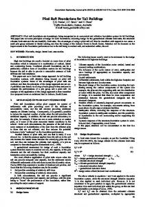
Figure 2. a) Location of equivalent raft and stress distribution for friction piles and b) layer thickness to be taken into account in the settlement calculation (Tomlinson, 2001) Gok and Togrol Method In this method; structural load of the building is assumed to be shared by the raft and the pile group, and the settlement of the raft and the pile group is calculated separately according to the different load sharing ratios (Gök and Toğrol, 2009). For several load sharing ratios, settlement of raft foundation is calculated using Eq. 1 and settlement of pile group can be calculated using Tomlinson method. By comparing the settlement values obtained for various load sharing ratios, the load sharing ratio is determined, in which settlement of the raft and the pile group are equal. Both systems will work together in this settlement amount.
15
Figure 3. a) Load sharing ratio and b) settlement amount of piled raft system (Wiesner and Brown, 1975) Randolph Method In the Randolph (1994) method, load sharing ratio between pile group and pile raft, pile raft stiffness and settlement of piled raft can be calculated by using Eq. 4-Eq. 7.
α=
QR = QPG
β=
QPG 1 = QPR 1 + α
0.2
KR ⎛ K ⎞ K 1 − 0.8 ⎜ R ⎟ PG ⎝ K PG ⎠ ⋅
(4)
(5)
⎛ KR ⎞ K PG ⎟⎠ ⎝ (6) K PR = ⋅ K PG ⎛ KR ⎞ 1 − 0.64 ⎜ ⎟ ⎝ K PG ⎠ Q S= (7) K PR where, α: Load sharing ratio between raft and pile group, β: Load sharing ratio between pile group and pile raft, KR, KPG, KPR: Stiffness of raft, pile group and piled raft respectively, S: Settlement of piled raft, Q: Design load.
1 − 0.6 ⎜
Poulos-Davis-Randolph (PDR) Method
In the PDR method, load sharing ratio between raft and piled raft (X) can be determined using Randolph (1994) method and piled raft settlement (S) can be established using Poulos and Davis (1980) method. X=
(1 − α rp )kr Qr = Qpr k pg + (1 − 2α rp )kr
(8) 16
S=
Q pr
(9)
k pr
k + (1 − 2α )kr k 1− α k r ln c α = 1− r
k =
pg
rp
pr
2
(10)
r
rp
pg
ς
rp
rc =
A nπ
ς = ln(rm / r ) rm = {0.25 + ξ [ 2.5 ρ (1 −ν ) − 0.25]} L ρ = Gavg / Gl ξ = Gl / Gb
(11) (12) (13) (14) (15)
(16) where; Qr, Qpr: Load carried by raft and piled raft respectively, kr, kpg, kpr: Stiffness of raft, pile group and piled raft respectively, αrp: Interaction factor, A: Raft area, n: Pile number, L: Pile length, rm: Maximum radius from pile axis, Gl, Gb: Shear modulus of soil along pile shaft and pile end respectively, ν: Poisson’s ratio of soil. Modifiying Poulos-Davis-Randolph (mPDR) Method
In the mPDR method, load-settlement behaviour of piled raft system (Fig. 4) can be determined and ultimate bearing capacity of piled raft can be found.
Figure 4. Simplified load-settlement curve for piled raft system (Poulos and Davis, 1980)
In Fig. 4, raft and pile group carry the load by sharing between each other up to point A and settlement of piled raft can be calculated by
S=
Q K PR
(17)
Pile group reach their ultimate capacity at the point A (QA) and after that point additional loads are carried by raft. Settlement of piled raft at the point between A and B can be 17
calculated by
QA Q − QA + K PR KR Q QA = PG S=
(18) (19)
β
where, KR, KPR: Stiffness of raft and piled raft respectively, S: Settlement of piled raft, Q: Design load, β: Load sharing ratio between pile group and piled raft (Eq. 4 - Eq. 5) Since load-settlement behaviour of raft and piles is hyperbolic, stiffness of raft and piles can be computed by ⎛
K PG = K i , PG ⋅ ⎜⎜1 − R f , PG ⋅ ⎝
⎛
K R = Ki , R ⋅ ⎜⎜1 − R f , R ⋅
QPG ⎞ ⎟ Qu , PG ⎟⎠
QR ⎞ ⎟ Qu , R ⎟⎠
(20) (21)
⎝ where, Ki,PG, Ki,R: Initial stiffness of pile group and raft, Rf,PG, Rf,R: Hyperbolic multiplier (0.5 for pile group and 0.75 for raft (Poulos, 2000)), QPG, QR: Load carried by pile group and raft, Qu,PG, Qu,R: Ultimate bearing capacity of pile group and raft
Simplified Finite Element Methods
By converting the piles in the piled raft system into "conjugate walls" with the same axial rigidity, the 3-dimensional piled raft system can be transformed into the 2D plane strain problem (Fig. 5).
Figure 5. Conversion of 3D piled raft system to 2D plane strain problem (Desai et al., 1974)
In this method, the raft is divided into strips to contain the piles on the same axis, and each strip is transformed into two dimensions from three dimensions. The elasticity modulus of the conjugate wall (Ecw) can be calculated by the following relation.
18
Ecw =
n p ⋅ Ap ⋅ E p Acw
(22)
where, np: Pile number on a raw, Ap: X-sectional area of pile, Ep: Elasticity modulus of pile, Acw: X-sectional area of conjugate wall.
Definition of Problem
A uniformly distributed structural load of 80000 kN is transferred to saturated silty clay from a 20 m by 20 m raft foundation (Fig. 6). Under that foundation, there are 64 piles having diameter (D) of 0.8m, length (L) of 19m and pile spacing (s) of 2.74m. In this study, load sharing ratios between raft and pile groups and settlement values of piled raft system are determined according to simplified analysis methods mentioned above.
Figure 6. Physical and mechanical properties of soil, raft and pile foundations
Calculation of Stiffness Parameters of Piled Raft System
Stiffness parameters of piled raft system must be calculated to use simplified analysis methods. Poulos and Davis (1974) proposed the following equations to calculate stiffness of raft foundation (Kr) by transferring to a circular foundation has equivalent area with raft.
Kr =
Q
ρz
(23) 19
ρz =
q⋅a ⋅I Es p
(24)
where; Q: Vertical load, ρz: Settlement of raft, q: Base pressure, a: Radius of equivalent circular foundation with raft, Es: Elasticity modulus of soil, Ip: Influence factor (0.95 for this problem). Axial stiffness of a single pile (kp) can be calculated by using following equations (Randolph, 1994).
4η 2π tanh( μ L) L +ρ Q (1 −ν )ξ ς μ L r0 ⋅G ⋅ r kp = p = w 1 + 1 4η tanh( μ L) L l 0 πλ (1 −ν )ξ μ L r0 where, η = rb / r0 , λ = E p / Gl , μ L =
(25)
2 , ϛ, rm, ρ, ξ: Defined in Eq. 13-Eq. 16 ςλ ( L / r0 )
respectively, r0, rb: Pile radius at pile top and bottom, L: Pile length, ν: Poisson’s ratio of soil Axial stiffness of pile group (KPG) can be calculated by using following equation (Poulos, 2000).
K PG = k p ⋅ n
(26)
where, n: Pile number, kp: Stiffness of a single pile. Stiffness of raft (Kr), single pile (Kp) and pile group (KPG) can be estimated as 298.6MN/m, 90.5MN/m and 724MN/m respectively using related equations above. Evaluation of Analysis Results
In the equivalent raft methods, traditional design method, load sharing ratio between pile group and piled raft, β is 1 and settlement, S is 0.079m according to Terzaghi and Peck method and 0.052m according to Tomlinson method. Before evaluating simplified piled raft analysis results, there is a benefit in specifying that pile group capacity is (since D=0.8m, L=19m, s=2.74m and n=64) ' Q f = (c '+ β ⋅σ avg ) ⋅ Af = 1231.9kN β = 0.3 , c’=0
(27)
Qp = N q ⋅σ ' ⋅ Ap = 1119.8kN , Ø’=25°, ψ=105°, N q = 13.6 (Janbu, 1976)
(28)
Qall = (Q f + Q p ) / FS = 1469.8kN
(29)
ng=0.7, QPG = ng ⋅ n ⋅ Qall = 65847 kN (30) where, Qf, Qp, Qall: Shaft, point and allowable bearing capacities of a pile, ng: Group efficiency factor, n: Number of pile, FS: Safety factor (1.6). In the Wiesner and Brown method, using Eq. 2, Eq. 3 and Fig. 3, it is concluded that Kp=3750, Kr=122070, β=0.48 and S=0.063 m. In the Gok and Togrol method, it is concluded that β=0.81 and S=0.041 m (Fig. 7).
20
S (m)
0.18 0.16 0.14 0.12 0.10 0.08 0.06 0.04 0.02 0.00
Radye Temel Kazık Grubu
QKG/QKR=0.81 S=0.041m
0
0.1
0.2
0.3
0.4
0.5
0.6
0.7
0.8
0.9
1
QKG/QKR (%) Figure 7. Solution of problem according to Gok and Togrol method
In the Randolph method, using Eq. 4-Eq. 7, it is concluded that Kpr=740.2MN/m, β=0.89 and S=0.108 m. In the PDR method, it is concluded that Kpr=849.6 MN/m, β=0.77 and S=0.094 m since rc=6.25 m, rm=33.25, ϛ=4.36 and αrp=0.37. In the mPDR method, it is concluded that β=0.75 and S=0.134 m since Kpr=579.7 MN/m and Kpr=289.7 MN/m. Another approach of mPDR method, load-settlement behaviour of piled raft system can be predicted (Fig. 8). Results of some calculations, using Eq. 5, Eq. 8 and Eq. 17-Eq. 21, are given in Table 1. Table 1. Settlement values of piled raft system for different load sharing ratios according to mPDR (II) method Q (MN ) 0 20 60 80 100 200 300 500
X
β
QPG (MN)
QR (MN)
KPG MN/m
KR MN/m
QA (MN)
S (m)
Q> QA
1.022 1.022 1.024 1.029 1.032 -
0.890 0.890 0.882 0.859 0.847 -
0.0 17.8 52.9 68.7 84.7 150.5 150.5 150.5
0.0 2.2 7.1 11.3 15.3 49.5 149.5 349.5
724.0 681.2 596.8 558.7 520.4 362.0 362.0 362.0
298.6 297.6 295.4 293.6 291.7 276.5 231.8 142.5
169.0 169.0 170.7 175.2 177.8 209.6 209.6 209.6
0.000 0.029 0.098 0.139 0.186 0.525 0.982 2.779
No No No No No Yes Yes Yes
500 Axial Load (MN)
400 300 200 100 0 0.0
1.0 2.0 Settlement (m)
3.0
Figure 8. Load-settlement behaviour of piled raft system according to mPDR (II) method 21
In the simplified finite element method, using Plaxis 2D, it is concluded that β=0.79 and S=0.145 m since Ecw=150800 MPa. Geometry of raft, conjugate walls and soil profile is shown in Fig. 9.
Figure 9. Geometry of piled raft system in Plaxis 2D
CONCLUSIONS
In this study, simplified piled raft analysis methods were evaluated. Except Wiesner and Brown method, load sharing ratio between pile group and piled raft were calculated in the range of %75 to %89 (Fig. 10a). This means that there is at most %10 difference between analysis methods used in this study. However there is a great difference in terms of settlement values of piled raft system, changes between 4cm to 14.5cm (Fig. 10b).
Figure 10. a) Load sharing ratio and b) settlement values obtained from all analysis methods
22
REFERENCES
Desai, C. S., Johnson, L. D. & Hargett, C. M. 1974. Analysis of pile supported gravity lock, ASCE Journal of Geotechnical Engineering, 100, 1009-1029. Fioravante, V. & Giretti, D. 2010. Contact versus noncontact piled raft foundations, Can. Geotech. J., 47, 1271–1287. Gök. S. & Toğrol. E. 2009. Basitleştirilmiş kazıklı radye hesabı, itüdergisi/d mühendislik, 8(5), 149-156. Hussein H.H., Karim H.H. & Shlash K.T. 2018. Theoretical verification for full-scale tests of piled raft foundation. In: Abu-Farsakh M., Alshibli K., Puppala A. (eds) Advances in Analysis and Design of Deep Foundations. GeoMEast 2017. Sustainable Civil Infrastructures. Springer, Cham Janbu, N. 1976. Static bearing capacity of friction piles. Journal of the Soil Mechanics and Foundations Division, ASCE, 95, SM1. Matsumoto, T., Nemoto, H., Mikami, H., Yaegashi, K., Arai, T. & Kitiyodom, P. 2010. Load tests of piled raft models with different pile head connection conditions and their analyses, Soils and Foundations, 50(1):63-81. Nguyen, D.D.C., Kim, D. & Jo, S. 2013. Settlement of piled rafts with different pile arrangement schemes via centrifuge tests, Journal of Geotechnical and Geoenvironmental Engineering,139, 1690-1698. Poulos, H. G., & Davis, E. H. 1974. Elastics solutions for soil and rock mechanics. New York: John Wiley & Sons Poulos, H.G. & Davis, E.H. 1980. Pile foundation analysis and design, John Willey and Sons, New York, USA. Poulos, H. G. 2000. Practical design procedures for piled raft foundations. Design applications of raft foundations, 425-468, London: Thomas Telford Ltd. Randolph, M. F. 1994. Design methods for pile groups and piled rafts, 13th ICSMFE, New Delhi, India, 61-82. Sanctis, L., Russo, G. 2008. Analysis and performance of piled rafts designed using innovative criteria, Journal of Geotechnical and Geoenvironmental Engineering, 134,8, 1118-1128. Saran, S. 1996. Analysis and design of substructures, limit state design, Balkema. Sawwaf, M. 2010. Experimental study of eccentrically loaded raft with connected and unconnected short piles, Journal of Geotechnical and Geoenvironmental Engineering, 146, 10, 1394-1402. Terzaghi, K. & Peck, R.B. 1967. Soil mechanics in engineering practise, John Willey & Sons, NY, 729. 23
Tomlinson, M. 2001. Pile design and construction, 7. Press, Prentica Hall. Wiesner, T.J. & Brown, P.T. 1975. Behavior of piled strip footings subjected to concentrated loads, Civ. Eng. Res. Rep. R275., Univ of Sydney, Aus.
24