Designing the Control Architecture for Algorithm Specific Custom Processors on FPGAs A. S. Bishell, D.G. Bailey, P. Lyons Institute of Information Sciences & Technology, Massey University Private Bag 11-222, Palmerston North, NEW ZEALAND Email:
[email protected],
[email protected],
[email protected] Abstract:
We consider the implementation of high-level image processing operations using a custom serial processor on an FPGA. When such operations are implemented directly using Handel-C, the algorithm executes serially, controlled by an implicit finite state machine. This architecture is then modified to use an explicit software controller. We demonstrate that these modifications increase design efficiency slightly, because the control logic does not have to be implemented in logic blocks. The architecture is also more flexible, as it is software driven without “hardwired” control. These benefits are at the cost of RAM for the control logic and increased time required to design the controller.
Keywords:
FPGA, image processing, algorithms, robot soccer, processor complex instruction decoder and possibly extra functional units. An algorithm-specific custom serial processor may be more appropriate for high level image processing operations.
1. INTRODUCTION An FPGA comprises a matrix of logic blocks that are interconnected with a switching network. The logic blocks and switching network can be reprogrammed to allow application-specific hardware to be constructed. FPGAs can be seen as a compromise between inflexible but fast application-specific integrated circuits (ASICs) and flexible but slower general purpose processors.
Main Processor
Coprocessor(s)
General Purpose Processor
---
General Purpose Processor
Parallel Dedicated Hardware (on FPGA)
More Software
Parallel Dedicated Hardware (on FPGA)
General Purpose Processor
More Hardware
General Purpose Parallel Dedicated Hard Processor Core Hardware (on e.g. PowerPC 405 FPGA) (on FPGA) General Purpose Parallel Dedicated Soft Processor Core Hardware (on e.g. MicroBlaze and FPGA) Nios (on ( FPGA))
Software
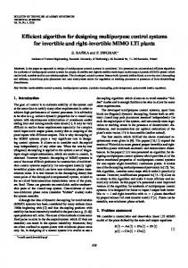
A typical image processing algorithm will involve low level operations (applied to each pixel within the image) as well as high level operations (those applied to regions or data extracted from regions with the image). On an FPGA, the low level operations of the algorithm are usually implemented with dedicated, parallel, hardware to exploit their inherent parallelism and to meet timing constraints [1]. However this form of implementation is inefficient for the high level operations which tend to be serial in nature. The lower volume of data involved in the higher level operations also means that parallelisation is not required to meet timing constraints. This makes a serial processor more appropriate for implementing many of the higher level operations. Figure 1 shows the spectrum of possible approaches for combining parallel hardware with a serial processor. A number of general purpose serial processor cores are available that can be implemented on an FPGA. However, general purpose serial processors need more extensive instruction sets to run arbitrary algorithms. This means a larger, more
Parallel Dedicated Hardware (on FPGA)
Custom Designed Processor (on FPGA)
Hardware
Parallel Dedicated Hardware (on FPGA)
---
Hardware
Parallel Dedicated Hardware (as an ASIC)
---
Figure 1: Implementation approaches for an image processing algorithm.
7
Implementing an algorithm using a high level hardware description language, such as Handel-C, “hardwires” the functional units and implicitly builds logic to control the execution of the “program”. Such control logic is effectively a finite state machine (FSM) with each state corresponding to a single executable statement. This approach has several limitations when used to implement serial algorithms:
Analysis of these colour patches to determine a robot’s identity, orientation and position. The first component involves high volume, pixellevel operations and is best implemented using parallel dedicated hardware. The second component is significantly lower in volume (there is only a small number of coloured patches) while the operations are more complex (involving division and arctangent). Since there is sufficient time available within each frame to process this data this suggests the use of a serial processor.
Functional units may be replicated if used in more than one place in the algorithm and explicitly reusing functional units can be clumsy requiring functions or shared procedures. Control logic is not reused, and grows with the complexity of the algorithm. There is also limited flexibility because the algorithm is “hardwired” in hardware. Changes to the algorithm require changing the architecture of the hardware by modifying the Handel-C program.
2. APPROACH To compare the hardwired FSM controller with an explicit software controller, the algorithm was first implemented in Handel-C (and had its implicit FSM created during compilation). Then the key functional units were identified, and an equivalent explicit software controller was designed. In doing this we hoped to answer the following research questions:
An explicit software controller is more appropriate for controlling a custom serial processor because it:
What footprint saving is achieved when using an explicit software controller instead of implicit FSM control? What general principles can be applied to determine which blocks of hardware should be allocated to instructions? Does the algorithm complexity justify the design of an explicit software controller?
Uses the same functional units, but schedules these through a sequence of instructions defined in software. This prevents functional units from being replicated (unless instructionlevel parallelism is exploited). Incurs a, mostly, constant overhead in terms of the control logic regardless of the complexity of the algorithm, and it shifts control logic from the fabric of the FPGA to RAM. Allows more flexibility since much of the algorithm’s behaviour can be changed with changes to software, and if changes to the architecture are required they are minimal.
Designing a custom processor with an explicit software controller involves determining both the hardware that implements instructions and the software that is executed. This is a form of hardwaresoftware codesign and requires both partitioning (analysing the hardware implementation to determine the boundaries of instructions, or the allocation of blocks of hardware to instructions) and determining the degree of control concurrency [2].
This research investigates the design and implementation of a scalar software architecture and a very long instruction word architecture, and compares these with the FSM created implicitly by Handel-C.
Achieving a minimal footprint requires trading off two constraining factors: maximisation of hardware reuse and minimisation of multiplexing to registers. Exploiting hardware reuse involves identifying blocks of hardware that are used repeatedly in the algorithm and implementing them as instructions. Reuse reduces the instruction granularity, leading to simpler, more generic instructions. Finer granularity, however, gives a larger instruction set requiring more multiplexing on the intermediate registers, both of which will increase the processor’s footprint on the FPGA.
Algorithm complexity plays an important role in the feasibility of an explicit software controller. As the algorithm complexity increases, so does the design cost in terms of analysing the algorithm to optimise the architecture to the particular problem. Beyond a certain point, a general purpose processor is more appropriate. Conversely if the algorithm is too simple a completely hardware implementation using a FSM controller may be more efficient in terms of both footprint and design cost. To compare the different controllers, we have implemented a robot soccer algorithm that identifies the members of two teams of robot soccer players in a plan-view video of the playing field. The algorithm has two components:
Hardware-software partitioning techniques can be grouped into two categories: the top-down approach examines the whole algorithm and attempts to decompose this single block into many blocks to be implemented as instructions. The bottom-up approach begins with an algorithm represented with primitive operations such as add and subtract and attempts to combine these to produce more complex instructions,
Processing of the input video stream from a camera over the robot soccer field to detect coloured patches on the robots.
8
usually with the aid of dataflow graphs (DFGs) representing basic blocks [3-5].
statements which may be used to define the software controller.
The top-down approach retains more of the original FSM controlled implementation than the bottom-up because it only decomposes blocks where necessary. This keeps instruction granularity relatively high and the degree of multiplexing low leading to a minimal footprint. When tuning the architecture for a specific application, the associated reduction in flexibility is less of an issue. Therefore the top-down approach is chosen for this problem.
opcode Memory
Fetch
Instruction Register
Scalar
Executes appropriate functional unit based Decode on opcode
The second aspect of hardware-software codesign for a custom processor involves determining the level of control concurrency required. This can be identified by classifying the architecture according to Flynn’s taxonomy [6], which groups architectures into four categories based on whether they use single or multiple instruction streams, and whether they use single or multiple data streams. Since the custom processor executes higher level image processing operations, which tend to be constrained to execute serially, there is little exploitable data-level parallelism and therefore multiple data streams are not necessary. The ability to use multiple instruction streams and exploit instruction-level parallelism in a controller is dependent on the existence and type of scheduling it employs. Scheduling is defined as the process of rearranging the instruction stream to exploit instruction-level parallelism and therefore minimise the execution time [7].
FUn
operand
VLIW Memory
Execute
Fetch
Wider memory
1st operand Instruction Register
2nd operand
FU1 FU2
th
n operand Wider instruction FUs execute register unconditionally and in parallel
FUn Execute
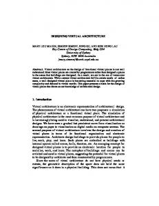
Figure 2: Comparison of scalar and VLIW architectures.
3. ROBOT SOCCER ALGORITHM The “players” in a robot soccer game each have four colour patches painted on their top (see Figure 3). The directional patch, A, is always red. The team patch, T is either blue or yellow denoting which team the robot is on. The identity patches, B and C, can be any combination of green, purple, pink or cyan/aqua but never the same colour, allowing for differentiation of up to six robots per team.
Dynamic scheduling uses additional hardware to rearrange the instruction stream during execution whereas static scheduling does this prior to execution avoiding this extra hardware cost. Furthermore, the instruction stream is known before execution so any parallelism that is present can be easily identified and exploited with static scheduling. Therefore we have avoided using dynamic scheduling which limits the resulting architecture to execute sequentially. We consider two types of sequential architectures: scalar and very long instruction word (VLIW) [8].
B
direction
A
100mm (20 pixels)
T C
A VLIW architecture stores multiple instructions in its instruction word and executes them in parallel. They are investigated because their control logic avoids the decode phase in the instruction cycle. This is shown in Figure 2. The VLIW uses one bit for each functional unit (in addition to the operands) to control its execution.
75mm (15 pixels)
Figure 3: A robot’s colour regions It is assumed that dedicated hardware has processed the image using some form of region detection and has produced a list of regions each with the following information:
Instruction prefetching (pipelining the fetch and execute phases) is a simple optimisation applicable to both architectures. However, this was not explored at this stage. At present we are only using the VLIW architecture to simplify instruction decoding rather than to exploit its ability to execute functional units in parallel.
Colour label Sum of x values of the pixels Sum of y values of the pixels Number of pixels
The robot identification algorithm processes this and produces a list of all robots each with the following information:
Low level control design for the controller [9] is unnecessary since Handel-C provides high level constructs such as while loops and switch/case
Identity
9
4. IMPLEMENTATION
Orientation X position Y Position
The FSM controlled processor was implemented first, since this is the simplest version of the algorithm to create and provides a basis for the software controlled versions. The explicit software controlled implementations are based around converting from the FSM controlled architecture rather than designing ab initio.
The algorithm that performs this transformation is appropriate for implementation on a serial processor because the number of operations is relatively small (with two teams of five players, a total of 40 regions represent all robots). In addition many of the operations are constrained to execute serially because of the iterative methods used to calculate arctangent and division [10, 11].
Several constraints were enforced for the software controlled implementations: A program counter (PC) and instruction register (IR) exist. The PC represents the address in instruction memory the instruction word is read from. The instruction register stores the currently executing instruction word. All registers are “shared” between all functional units. It is up to the programmer to ensure they are accessed correctly. The PC and IR are treated like any other register. The controller reads the instruction register and calls functional unit(s) passing the appropriate operand(s). It executes indefinitely until a terminate flag is set. Functional units must take a static number of clock cycles (but may be multi cycle) forcing loops to be partitioned into multiple instructions. Direct addresses are used in operand fields because it results in a smaller program ensuring the instruction memory is kept minimal and simplifies programming.
The region and robot information are each represented as an array of structures stored within the fabric of the FPGA. Distributed RAM is used because it allows 16 bits to be stored per logic lock instead of 1 bit per logic block for registers. This limits access to one location per clock cycle but this is not a hindrance since the algorithm is executed serially on the custom processor. The algorithm must first find a robot by finding a team coloured region, T, then search for regions belonging to the same robot and calculate its orientation and identity by based on the directional patch, A, and both identity patches, B and C, respectively. This is shown in Figure 4.
For every region If it is blue or yellow (a team colour region) Set the current robot’s position with the centre of gravity of this region
The explicit software controlled implementations still have an implicit FSM created for controlling each functional unit. Therefore the software implementations could be considered as a hybrid between explicit software and implicit FSM control.
For every region, while the orientation or identity is unknown for the current robot If it is not blue or yellow (a team colour region) Determine the region’s centre of gravity
Given these constraints, the process of creating the software controller versions is detailed in the following sections.
If it belongs to the current robot If it is red (a directional region) Calculate the current robot’s orientation from the centre of gravity of this region and the robot’s position
4.1
Creating a Skeleton Controller
A skeleton software controller is created, introducing the following components into the architecture:
Else it must be green, purple, pink or cyan/aqua (an identity region)
If a directional region has not been found for this robot Remember this region for when the second one is found Else Set the current robot’s identity based on both identity regions found
4.2
Instruction register. Program counter. Instruction memory. A control loop that executes until a terminate flag is set. Basic Functional Units
Two functional units are created as these are considered necessary in any software implementation:
Figure 4: Algorithm behaviour
Terminate: Sets the terminate flag causing the controller to halt execution of software.
10
VLIW implementation also must have a 1 bit “execute” field implemented in the functional units and in the appropriate place in the instruction fields. The VLIW controller is essentially encoding the same information as the opcode by specifying the correct place for the execute bit in software.
Jump: Unconditionally sets the PC to the direct value provided in the operand. 4.3
Register accessibility
Registers are made globally accessible since they may be shared between multiple functional units. They remain in distributed RAM, as with the FSM implementation, so that the architectures remain identical and conclusions can be drawn solely between the different controllers. 4.4
5. RESULTS The results for all three implementations are shown in Table 1. These are created in Handel-C and targeted at a Xilinx Spartan-II FPGA executing at 20 MHz (sufficiently fast enough to process the video stream in real time). The Xilinx ISE tool chain is used to place and route the design onto the FPGA.
Loop constructs
Loop constructs used in the FSM controlled processor are implemented as multiple as multiple explicit instructions. The MIPS [12] instruction set architecture is used as inspiration for this and results in the following instructions:
Table 1: Implementation results FSM Scalar Logic Blocks 1154 1140 Shift Registers 1 1 Distributed RAM (32x1) 102 102 Distributed RAM (16x1) 78 78 Block RAMs 0 1
Loop setup, if required Loop break detection Loop iteration Loop increment or decrement, if required
The general purpose jump instruction is used to jump back to a loop’s break detection instruction after each iteration. In this initial implementation we do not make these instructions general purpose resulting in, potentially, four new instructions for every loop construct that is implemented. 4.5
The shift registers and distributed RAM are the same for all three implementations since the architectures (but not their controllers) are the same and not relevant for comparisons between controller footprint.
6. CONCLUSIONS
Programming
The use of an explicit software controller instead of the implicit FSM control provides less reduction in logic block usage than expected, in this application. Only a modest saving of 14 logic blocks (approximately 1.2%) is achieved with the scalar architecture and no savings are achieved with the VLIW architecture. This is at the expense of 1 or 6 block RAMs respectively used as instruction memory, resulting in an overall increase in resource utilisation for both software controllers.
This is the most difficult and time consuming task when creating an explicit software controller. It involves not only specifying the instructions in the correct order but also assigning the correct operands. However, specifying jump addresses while constructing the program is difficult because the addresses of certain instructions constantly change. We thus use macro expressions to define labels which have values assigned to them once the program structure has been completed. This task is performed manually for this application but it could easily be automated by an assembler, reducing the design cost for an explicitly software controlled processor. 4.6
These results support the assumption that the implicit FSM controller is optimised and an explicit software controller is less efficient when implementing the same behaviour. However, it was expected that the shifting of control logic to instruction memory would result in greater reductions to logic block usage than what is shown by the results.
Width and Depth of Controller Components
The depth of the instruction memory is set to the minimum required to store the assembly program that was written. This determines the width of the program counter, and thus the operand size for jump instructions. This then allows the width of the instruction memory and instruction register to be set (these also depend on the number of functional units created). 4.7
VLIW 1154 1 102 78 6
In this application, the relatively expensive functional units (those for arctangent and division) were only used in one place within the serial algorithms. For a more complex algorithm, where the resource intensive functional units can be reused, the savings from the software implementations are expected to be greater.
Controlling a VLIW Architecture
Nevertheless, an explicit software controller provides greater flexibility than FSM control. If the algorithm that executes on the custom processor is changed then potentially only the software needs to be altered and
The previous steps are applied to both the scalar and VLIW explicit software controllers; however the
11
8. REFERENCES
possibly small changes to the architecture. In addition, as an algorithm’s complexity increases logic block savings should also increase in the software implementations since they reuse control logic more efficiently than a FSM. The guidelines that can be applied to hardwaresoftware partitioning are expressed in the implementation section. Given an initial architecture, the footprint can be further optimised if necessary by tuning the instruction granularity. This involves two tasks: Combining multiple instructions into a single instruction. Decomposing an existing instruction into multiple instructions. A balance is required to ensure the explicit software controller efficiently uses resources but also has the desired flexibility. If instructions are too fine grained then the expensive multiplexing of registers begins to offset the savings made through hardware reuse and the shifting of control logic into RAM. However, fine grained instructions are more able to be reused resulting in an architecture with greater flexibility. Similarly if instructions are too coarse grained then less control logic is represented in software and more of it is represented in the functional units leading to less multiplexing of registers but also less functional unit reuse. Investigating the detailed effects of changing instruction granularity to improve flexibility and reduce footprint is a topic of further work. The complexity of the robot soccer player identification algorithm is such that it is probably best implemented directly in hardware rather than using an explicit software controller. The algorithm consists of a single set of nested loops, with the complex operations only occurring at one place within the loop. A consequence of this is that the complex functional units are not reused within this algorithm. In these circumstances, the direct FSM implementation will always be more efficient than an explicit software controller when the resources required for the instruction memory are taken into consideration. This fact was discovered in hindsight through this application. These factors suggest that it is necessary to analyse an algorithm to determine if there will be any significant level of functional unit reuse before designing an explicit software controller.
[1]
C. T. Johnston, K. Gribbon, and G. D. Bailey, "Implementing Image Processing Algorithms on FPGAs," in 11th Electronics New Zealand Conference (ENZCon04), Palmerston North, New Zealand, 2004, pp. 118-123.
[2]
D. E. Thomas, J. K. Adams, and H. Schmit, "A Model and Methodology for HardwareSoftware Codesign," in IEEE Design & Test of Computers. vol. 10, 1993, pp. 6-15.
[3]
P. Brisk, A. Kaplan, and M. Sarrafzadeh, "Area-Efficient Instruction Set Synthesis for Reconfigurable System-on-Chip Designs," in Design Automation Conference (DAC), San Diego, California, USA, 2004, pp. 395400.
[4]
K. Atasu, L. Pozzi, and P. Ienne, "Automatic Application-Specific Instruction-Set Extensions Under Microarchitectural Constraints," International Journal of Parallel Programming, vol. 31, pp. 411-428, 2003.
[5]
M. Arnold and H. Corporaal, "Designing Domain-Specific Processors," in 9th international symposium on Hardware/software codesign Copenhagen, Denmark: ACM Press, 2001.
[6]
M. Flynn, "Some Computer Organizations and Their Effectiveness," IEEE Transactions on Computers, vol. C-21, p. 948, 1972.
[7]
M. Flynn, Computer Architecture: Pipelined and Parallel Processor Design: Jones and Bartlett Publishers, 1995.
[8]
J. A. Fisher, "Very Long Instruction Word architectures and the ELI-512," in 10th annual international symposium on Computer architecture, Stockholm, Sweden, 1983, pp. 140-150.
[9]
J. L. Hennessy and D. A. Patterson, Computer Organization and Design: The Hardware/Software Interface 3rd Edition, 3rd ed.: Morgan Kaufmann, 2004.
[10]
J. E. Volder, "The CORDIC Trigonometric Computing Technique," IRE Transactions on Electronic Computers, vol. 8, pp. 330– 334, September 1959.
[11]
J. S. Walther, "The Story of Unified Cordic," VLSI Signal Processing, vol. 25, pp. 107112, 2000.
[12]
G. Kane, MIPS RISC Architecture: PrenticeHall, 1989.
7. ACKNOWLEDGMENTS The authors would like to acknowledge the Celoxica University Programme for generously providing the DK4 Design Suite, and the Xilinx University Programme for providing the ISE Foundation.
12