Abstract. In order to get the trajectory of moving object using single-pixel imaging system, an algorithm is proposed. The same pseudorandom masks are ...
MATEC Web of Conferences 160, 07002 (2018) https://doi.org/10.1051/matecconf/201816007002 EECR 2018
Detecting the Trajectory of Moving Object for Single-Pixel Imaging System Shao Hui , Wu Dongsheng ,Chen Jie, Li Zhao, Xu Xiaoxue, Zhai Fangbing School of Electronic and Information Engineering, Anhui Jianzhu University, Hefei, 230601, China
Abstract. In order to get the trajectory of moving object using single-pixel imaging system, an algorithm is proposed. The same pseudorandom masks are employed to illuminate the different time scene. A time weighted sum of the background correction signals is employed to get the trajectory information using compressed sensing (CS) method. In ideal situation, we can obtain other parameters (e.g., speed, orientation) besides the trajectory. However, the reflective intensity of the object can be change due to the reflective angle change caused by the motion in some situations. This will mislead for achieving the speed, orientation parameters. In order to eliminate this effect, a division method is utilized. At last, the computer simulation results prove the effect validity of the proposed algorithm.
1 Introduction Localization of changes in a scene is an important task in a large number of application and disciplines, such as video surveillance, remote sensing, medical diagnostics, and scientific research [1-5]. Detection of changes is the central step in motion detection and moving object tracking applications. Typically, detection of changes is accomplished by examining the difference between consecutive frames within a sequence of image frames. The location of changes is obtained by subtracting the two consecutive frames that has been widely applied in common imaging system based on CCD detectors. From the numbers of the different images, we can get the trajectory of moving object. Now, there are a lot of methods employed to get the trajectory, such as background subtraction [2,3], optical flow [4] and so on [5]. In recent years, single-pixel imaging system [6-13] has been paid more and more attention and has been successfully applied in many fields, such as threedimensional imaging [6-9], optical security [10] and so on [11]. Single-pixel imaging system needs to modulate the illumination light intensity, and the reflected light is detected by single-pixel no-scanning detector. Compressed sensing (CS) [14-16] is a new sampling theory developed from the sparse characteristic of the signal. In the far smaller than Nyquist sampling rate, the signal is recovered by CS method. Now, compressed sensing algorithm is largely utilized to recover the object image in single pixel imaging system. Sun [6] employed the different detectors with different visual angles to obtain the two-dimensional images of the object. According to the shape from shading technique, the three-dimensional image of the object is obtained. C.Z. et. al. [7] according the return signal distribution to obtain the three structuration of the object. In this method, the
two-dimensional image of a certain range is achieved by the certain-time returned signal. The three-dimensional image can be acquired from these two dimensional images. Photon counting single-pixel lidar is built by the [8] and applied to obtain three-dimensional image and video at 14 frames per second. A background subtraction method [8,9] for object tracking at low light levels is proposed. From the numbers of the object tracking images, we can get the trajectory of moving object. But it will need a lot of CS operations. Trajectory of the interested object is an important subject for analyzing the state and estimating motion parameters in remote sensing, tracking. However, there is no research on trajectory acquisition for single pixel imaging system. In this paper, we proposed a trajectory acquisition method.
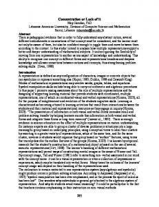
2 Compressive detecting the object trajectory Figure 1 shows the typical single pixel imaging system. Light transmitted by the light source is collimated by the Lens and then illuminate the object. The reflective/transmission light is modulated by the modulation information-system and then collected by the Lens to the single pixel detector. The light emitted from the light source can be continuous, also can be pulsed. In three dimensional imaging applications, the pulse light source is generally used [7,8]. Modulation informationsystem is a key device. Digital Micro-mirror Device (DMD) [17] which is invented by L. J. Uorbeck in 1987 is often employed in single pixel imaging system for the incoherent light source. The light modulated by the DMD can be described as two elements (0,1) matrix, and we call it as mask. Phase spatial light modulator (SLM) is employed for the coherent light source. In this situation, the mask is computed by the computer program based on
© The Authors, published by EDP Sciences. This is an open access article distributed under the terms of the Creative Commons Attribution License 4.0 (http://creativecommons.org/licenses/by/4.0/).
MATEC Web of Conferences 160, 07002 (2018) https://doi.org/10.1051/matecconf/201816007002 MATEC Web of Conferences EECR 2018
the light transmission equations. The whole imaging process requires many different modulations. Figure 2 shows the different masks.
O
basis vectors. The scene is usually complex, so the sparse transform is needed. The equation can be described as:
MI
Ol = Ψ α
L2
LI LS
(3)
where Ψ is the sparse operator (e.g., wavelet, Fourier, Total Variation operators), α is the sparse signal. We can rewrite the Eq. (2) as
SPD
I = B· Ol = B·Ψ α
(4)
Usually CS algorithm is employed to solve l1-norm minimization problem stated in general as follows: Figure 1. Structure diagram of typical single pixel imaging system. LS: light source; LI: lens; O: object; MI: modulation information-system; L2: lens; SPD: single pixel detector.
min ||α||1 such that I = B·Ψ α
According to the above method, we can get the object information.In order to track a moving object by removing static components from a scene, a compressive subtract object tracking method is proposed. The same pseudorandom masks are project to the different time scenes. If the detected signals produce the same correlation value, it would imply that the scene is identical. The opposite situation would reveal information about the changes. The method can be described as:
Now, we analyze the theory of the single-pixel detector imaging system. Matrix O is used to denote the object information, and the size of O is N=N1×N2. Matrix Bn is employed to describe the n-th mask matrix information, and has the same size as O. The detected signal from the single pixel detector in the n-th acquisition denote as in . For the n-th acquisition, we can express as:
min ||α||1 such that ΔI = B·Ψ α
(1)
Where Bnl and Ol show the column vectors of the matrixs Bn and O, respectively. In order to recover the object information, a lot of detected data for different masks are used. The imaging process can be expressed in mathematical form as follows:
I = B· Ol
(6)
where ΔІ is the difference between two detected signals, and equal to ΔІ=I1-I2. If we use this method to get the trajectory of moving object, a series of operations are needed. First, the Eq. (6) is used to get the change information between the two adjacent time scenes. And then according to the above many change information, computer algorithm is employed to obtain the trajectory of moving object. This treatment is complicated. In the following section, we will propose a simple method to get the trajectory of the moving object. The same pseudorandom masks are project to the scenes in different times ( t1, t2, … , tn ), and we describe the detected singles as ( I1, I2,…, In ). Suppose the moving object enter the scene in the moment t2, the detected singles I1 regard as the background singles. We can get the summed and weighted summed signals as following:
Figure 2. Different masks in the imaging process
in = Bnl · Ol
(5)
(2)
where I is the detected intensity vector form the single pixel detector which can be expressed as I =[i1, i2, i3…, iM]T , symbol T denotes the matrix transpose operation, B denotes the mask matrix as B=[B1l; B2l; B3l; …; BMl]T. Because the object has N unknown parameters, the number of the detected data have to greater than or equal to N in order to recover the accurate object information. Otherwise, there are many solutions to the above equation. Fortunately, CS algorithm offers the way which let us to recover the object information from a smaller number of samples than that of the object information. If the coefficients of a signal in a group of vectors containing a large number of zero elements, this signal is sparse. In fact, most natural signals are sparse mapped in soma
I S=ΔІ1+ΔІ2+…+ΔІh
(7)
I SW=α(ΔІ1)+2α(ΔІ2)+…+hα(ΔІh )
(8)
Where ΔІh=Ih-I1 is background correction signals, and the parameter α is time parameter. Using the above Eq. (7) as the detected signal and submitting it in the Eq. (6), the result Os show the trajectory of the moving object. However, we cannot get other parameters (e.g., speed, orientation) from this result because time information lost. We using a time weighted coefficients in the Eq. (8). In
2
MATEC Web of Conferences 160, 07002 (2018) https://doi.org/10.1051/matecconf/201816007002 EECR 2018 EECR 2018
ideal situation, the reflective intensity of the object is not change. Using the above Eq. (8) as the detected signal and submitting it in the Eq. (6), we can get the trajectory of the moving object according to gray value of the result Os, and other parameters can also obtained. However, reflective intensity is related to the reflective angle in some situations. The motion of the object caused the change of the reflective angle. At this time, the trajectory can also obtained by the gray value, but the achieved other parameters (e.g., speed, orientation) will take misleading due to the inconsistency of the reflective intensity. Therefore, we need to correct this inconsistency by the intensity normalization. A division method is employed as:
T Ows Os
(9)
where ε is the regularization parameter. In the next simulation, we will verify the validity of the proposed method to get the trajectory of moving object, and the accurately information (e.g., speed, orientation) can also be acquired.
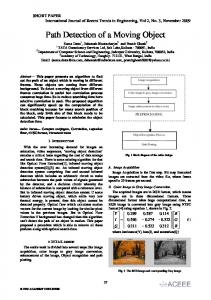
Figure 4. The trajectory of moving object: (A) result from the Eq. (7); (B) result from the Eq. (8).
3 Simulation Experiments
In order to simulate the change of the object reflectivity intensity, a random coefficient is used in this simulation. The reflectivity intensity of the background assumes constant. The part of the image frame sequence in the simulation experiment two are shown in Figure 5. The other parameters are the same as the first case. Figure 6 (A) and (B) are the results Os and Ows, respectively. Due to the change of the object reflectivity intensity, the trajectory can obtain, but other parameters (e.g., speed, orientation) cannot achieve. A division method is employed to eliminate the effect of the object reflectivity intensity change. Figure 6(C) shows the final result. The regularization parameter is equal to 0.01. Complete accurate information can be obtained from the final result.
In this section, we will give the results from the two situations:1) object moving in the scene, but the reflective intensity unchanged;2) object moving in the scene, and the reflective intensity change. Figure 3 shows the part of the image frame sequence in the simulation experiment one. Frame 1 is the background. In the next frames, a circular object with uniform reflectance moving into the scene. The number of image frames is twenty. One thousand random intensity distribution patterns are used in this simulation. Using these patterns project on the frames and detecting the signals, the results Os and Ows can be obtained and are shown in Figure 4. Figure 4(A) is the trajectory of the moving object. However, because of the lack of time information, other parameters (e.g., speed, orientation) are unable to distinguish from the result Os. This result is consistent with the theoretic analysis. Result Ows contains the time information which is expressed as the gray value. According to this result, we can obtain the orientation parameter. If the distance between two points is known, velocity parameter can also be solved. Frame 1
Frame 3
Frame 5
Frame 7
Frame 9
Frame 11
Frame 13
Frame 15
Frame 17
Frame 19
Frame 1
Frame 3
Frame 5
Frame 7
Frame 9
Frame 11
Frame 13
Frame 15
Frame 17
Frame 19
Figure 5. The part of the image frame sequence in the simulation experiment two.
Figure 3. The part of the image frame sequence in the simulation experiment one.
3
MATEC Web of Conferences 160, 07002 (2018) https://doi.org/10.1051/matecconf/201816007002 MATEC Web of Conferences EECR 2018
2.
3. 4.
5. 6.
7.
Figure 6. The trajectory of moving object: (A) result from the Eq. (7); (B) result from the Eq. (8); (C) result by the division method Eq. (9).
8.
4 Conclusions
9.
We proposed an algorithm to obtain the trajectory of moving object for single-pixel imaging system. Our approach requires detecting the signals from the different time scenes using the same pseudorandom masks. By the sum of the background correction signals, the trajectory of moving object is obtained using the CS method. Other parameters (e.g., speed, orientation) are also important for analyzing the object state. A time weighted sum of the background correction signals is employed to get the trajectory information. In ideal situation, we can obtain the important parameters besides the trajectory. But in some situation, the reflective intensity of the object can be change due to the reflective angle change caused by the motion. In order to eliminate this effect, a division method is utilized. From the final result, we can obtain the accurate information.
10. 11. 12.
13.
Acknowledgments
14.
This research is supported by Natural Science Foundation of Anhui Province (KJ2016A149, KJ2015ZD14), Research Found for Doctoral Program of Anhui Jianzhu University (2015QD07), National Natural Science Foundation of China (61471002).
15.
16.
References 1.
P. M. Lane and M. Cada.Optical Fourier processor and point-diffraction interferometer for moving-
17.
4
object trajectory estimation. Appl Optics 38, 43064315 (1999). A. Elgammal, R. Duraiswami, D. Harwood, and L. S. Davis. Background and foreground modeling using nonparametric kernel density estimation for visual surveillance.P IEEE 90, 1151-1163 (2002). D. S. Lee. Effective Gaussian mixture learning for video background subtraction. IEEE T Pattern Anal 27, 827-832 (2005). K. Ma and H. Y. Wang.Region-based nonparametric optical flow segmentation with pre-clustering and post-clustering. IEEE International Conference on Multimedia and Expo, Vol I and Ii, Proceedings, A201-A204 (2002). J. Badenas, J. M. Sanchiz, and F. Pla.Motion-based segmentation and region tracking in image sequences. Pattern Recogn 34, 661-670 (2001). B. Sun, M. P. Edgar, R. Bowman, L. E. Vittert, S. Welsh, A. Bowman, and M. J. Padgett.3D Computational Imaging with Single-Pixel Detectors. Science 340, 844-847 (2013). C. Z. Wen, L. Gong, J. Jiao, E. Li, M. Chen, H.Wang, W. Xu, S. Han. Three-dimensional ghost imaging ladar. arXiv:1301.5767 (2013). G. A. Howland, D. J. Lum, M. R. Ware, and J. C. Howell. Photon counting compressive depth mapping .Opt Express 21, 23822-23837 (2013). O. S. Magana-Loaiza, G. A. Howland, M. Malik, J. C. Howell, and R. W. Boyd. Compressive object tracking using entangled photons. Appl Phys Lett 102 (2013). W. Chen and X. D. Chen. Ghost imaging for threedimensional optical security. Appl Phys Lett 103 (2013). D. Shi, S. Hu, and Y. Wang. Polarimetric ghost imaging. Opt Lett 39, 1231-1234 (2014). M. Stuff, B. Thelen, J. Garbarino, and N. Subotic. Compressive Sensing and 3-D Radar Imaging. 2012 IEEE Statistical Signal Processing Workshop (Ssp), 540-543 (2012). A. Colaco, A. Kirmani, G. A. Howland, J. C. Howell, and V. K. Goyal. Compressive Depth Map Acquisition Using a Single Photon-Counting Detector: Parametric Signal Processing Meets Sparsity. 2012 IEEE Conference on Computer Vision and Pattern Recognition (Cvpr), 96-102 (2012). W. Chan, K.Charan, D.Takhar, etl.. A single-pixel terahertz imaging system based on compressed sensing. Appl Phys Lett 93 121105(2008) E. J. Candes, J. Romberg, and T. Tao. Robust uncertainty principles: Exact signal reconstruction from highly incomplete frequency information. IEEE T Inform Theory 52, 489-509 (2006). Y. Rivenson, A. Rot, S. Balber, A. Stern, and J. Rosen. Recovery of partially occluded objects by applying compressive Fresnel holography. Opt Lett 37, 1757-1759 (2012). http://www.ti.com/lsds/ti/dlp/.