Jun 9, 2017 - Brian V. Funt. Edwin C. Bryant. Abstract. Internal defects can be seen clearly in computer tomography (CT) images of sawlogs. In a sawmill, CT-.
Detection of internal log defects by automatic interpretation of computer tomography images Brian V. Funt Edwin C. Bryant
Abstract Internal defects can be seen clearly in computer tomography (CT) images of sawlogs. In a sawmill, CTscan technology could be applied to improve the overall grade and quantity of lumber produced. We describe a computer system that automatically interprets CT-scan images and successfully identifies the knots, rot, and cracks occurring in a log. The computer program uses the high density and elliptical shape of knots to distinguish them from good wood, and the low density and rough texture of rotten areas to separate rotten wood from sound wood. Interpretation results are presented from tests with both green and dry wood samples of cedar, hemlock, and fir. Computer controlled sawing systems have recently been introduced into many sawmills. Generally, such systems are situated a t the headrig and analyze data concerning the external shape of the log acquired through a set of light beams and photosensors or a closed-circuit video camera. Because these systems measure the shape of the log more accurately than a human operator, they are able to increase the lumber yield of the log. The crucial limitation for both the computer-controlled system and human operator, however, is that neither can tell what the log looks like internally before it is cut. Computer tomography, an x-ray technique that provides cross-sectional images (CT-scans) of objects, provides an opportunity to overcome this limitation. The detailed "picture7' of the inside of a log that a CT-scanner produces can be used not only to increase the quantity of lumber obtained, but its quality as well. For example, rather than ending up with an unplanned distribution of knots throughout the boards, CT-scan information could be used to plan the location of knots, thereby optimizing the amount of clear, knot-free lumber. While CT-scan technology has been rapidly spreading in hospitals as a diagnostic tool, its high cost has slowed its introduction into industrial settings. This
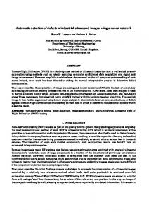
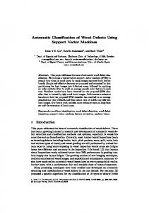
situation is changing as work proceeds on industrial scanners for nondestructive testing. Although cost is a problem in terms of the economic viability of CTscanners in sawmills, perhaps the most serious technical difficulty is speed. Since a rate of three logs per minute is common in many sawmills, very little time is available in which to collect and interpret an extremely large amount of data. The amount of data presents a problem for the computer and human operator alike. Figure 1 shows a CT-scan of a hemlock log. After the scan was taken, the log was crosscut in the same plane as the scan. The exposed face of the log is shown in Figure 2 where we can see a surprising similarity between the CT-scan and the photograph. Many details of the log's structure, such as its growth rings and knots, are visible in the scan. The scan reveals them because the scanner measures x-ray absorption, which primarily corresponds to a material's density. The density of knots and slow winter growth exceeds that of the fast summer growth, and this is depicted in the scan by the brighter white in these areas. The checks appearing in the photograph were not present at the time the Kg was scanned. A single CT-scan provides a cross-sectional view a t only one location. To form a complete model of the internal structure of a log requires a sequence of scans a t many locations along the length of the log as shown in Figure 3. The number of scans required depends on the
The authorsare,respectively,AssociateProfessor, Dept. of Computing Science, and Systems Analyst, Laboratory for Computer and CommunicationsResearch,SimonFraserUniv., Vancouver, B.C.,Canada,V5A 1S6. The authors wish to thank Kim Adamson-Sharpe,SFU, andJan Aune of MacMillan Bloedel Research, Inc., and Arthur Burgess of the Univ. of British Columbia for their contributions to this project.This work was supported by the Science Council of British Columbia under ant #47 (RC-5). This paper was received for publication in K n e 1985. 0 Forest Products Research Society 1987. Forest Prod. J. 37(1):56-62.
JANUARY 1987
Figure 1. - CT-scan of a hemlock log in which white areas corresponding to knots are clearly visible.
desired level of detail. If knots as small as 1 inch in diameter are to be found. then scans must be made at less than l-inch spacings: A log 24 feet long scanned a t l-inch intervals results in 288 scans in which all the knots and rotten areas must be identified and a cutting strategy decided upon in less than a minute. Since a human operator would be overwhelmed by this number of images, computer interpretation of the scans is essential. In other words, the computer must be able to automatically identify the knots, rot, cracks, and holes in a CT-scan before CT-scanners can be usefully applied in sawmills. Others have explored the use of CT-scans for defect detection in sawmills (1. . , 6., 7). . Portable scanners have also been constructed for use on living trees and standing telephone poles (3, 5). For these applications there will be relatively few scans, so interpretation by a human operator is feasible. The only automatic analysis technique that has been described is gray level thresholding to identify knots (8).Therefore, the goal of the project described in this paper is the completely automatic analysis of a CT-scan to identify all knots, rot, holes, cracks, and clear wood. Equipment All the CT-scans were taken with a Siemens Somatom DR2 scanner a t a local hospital. This scanner has a resolution of 256 by 256 pixels where each pixel is a number in the range 0-2,047, representing the x-ray absorption of the material. For most materials and wood in particular, this full range is unnecessary. The display and image processing equipment, an International Imaging Systems (11s)Model 70 video-rate image processor (g), capable of operations such as subtraction or multiplication of two images in 1/30 of a second, easily manipulates pixels in the range 0-255. The images were transferred from the scanner to the IIS Model 70 by computer tape. As the data was unloaded from the tape, it was examined to select the appropriate range of 256 values from the 2,048 available. In the cases where the
Figure 2. - Photograph of the face of the log that was ex~osedwhen it was crosscut where it had been scanned. he checks appearing in the photograph were not present at the time of the scan,
U
FOREST PRODUCTS JOURNAL
vol. 37, NO. I
Figure 3. - Many scans of the log must be made in order to construct a complete model of what is inside it. This sequence of scans was taken at 16 mm intervalsalong a fir log with knots and severe checking. 8
range of 256 was not broad enough to encompass a11 the data, the data was linearly scaled to fit. Computer algorithms A computer program has been written which successfully identifies knots, rot, holes, and good wood in CT-scans of sawlogs. The algorithms will be briefly described here, although for more detail the reader is referred to Funt and Bryant (2). Three classes of features are readily visible in the CT-scans: 1)the lightness or darkness of a region; 2) the shape of a region of a particular brightness; and 3) brightness textures or patterns. Knots are easily discerned by their whiteness and roughly elliptical shape. The air surrounding the log as well as holes and cracks appears very dark, while good wood shows up in the circular pattern of the growth rings. The hardest feature to distinguish tends to be rot. The rotten region in Figure 4 is identified on the basis of its dark shade (which is not quite as dark as that of a check) and by the disruption in growth ring pattern it causes. All of these features are used by the computer program in its decisionmaking process.
Classification by density The program first categorizesthe various regions in a scan on the basis of density. The four density ranges from lowest to highest are: 1) air; 2) mixed rot and good wood; 3) entirely good wood; and 4) knots. The program uses a frequency-intensity histogram to discover what the boundaries between these ranges should be. The program represents a CT-scan as a 256 by 256 square array of numbers in the range 0 to 255. Each number codes the density of a particular picture element, or "pixel," in the scan. The histogram is a graph of the number of pixels in the scan having each of the 256 different values. A typical histogram will have several peaks, one corresponding to air, a second to heartwood, a third,to sapwood, and a fourth to knots. Of course, if there are no knots, or if the wood is very dry (which reduces the density of the sapwood), not all of these peaks will be present. Finding the boundaries between these various density ranges reduces to the problem of locating the peaks and valleys in the histogram. This is accomplished by calculating the second and third derivatives of the histogram viewed as a one-dimensional function. Where the second derivative is zero corresponds to maxima and minima in the histogram, and where the third derivative is zero corresponds to maximal curvature in the histogram. The histogram (frequency of occurrence versus intensity) of Figure 4 is plotted in the top graph of Figure 5. The middle and bottom graphs show the second and third derivatives of the histogram, respectively. The graphs are aligned so the correlation between the zero-crossings and the peaks and valleys of the histogram can be seen. The arrows show the boundary points that the program finds. It chooses the leftmost and rightmost zero-crossings of the third derivative with positive second derivative (to ensure a maximum is found) for the boundaries of the two outer density ranges, and the zero-crossing of the second derivative with positive first derivative for the boundary between good wood and rot that is intermingled with
Figure 4. - Dry hemlock log with a rotten spot.
58
A
Figure 5. -The histogram (top) and its second (middle) and third (bottom) derivatives shown vertically aligned. The boundaries the program chooses for this histogram are indicated by the arrows.
JANUARY
indicates sound wood even if the wood has quite low density. The program therefore uses low growth ring uniformity as a measure of rottenness. The first step in the test of growth ring uniformity is to find the growth rings. The program finds individual edge elements with a standard edge-detection algorithm (4). For each pixel that is on an edge, the directions to neighboring pixels (that are themselves on edges), are averaged to yie!d a direction for the edge at the current pixel. The edge directions a t all pixels within a small local area are then compared. The higher the percentage having the same direction, the higher the growth ring uniformity is taken to be. Pixels where low-density and lowuniformity combine are marked as rotten. As in the case of knots, these pixels are then amalgamated into connected, convex regions.
Figure 8. - A scan of the hemlock log of Figure 4 taken at the same location but when it was green. good wood. Experimentation with many different scans indicated that these zero-crossings were the ones to use. Although the high density "peak is very small because there is no sapwood and little knot wood, the program finds it nonetheless. Shape and pattern analysis The CT-scan can be segmented into the four basic types of regions on the basis of the boundaries the program determines from the histogram. These regions are shown in Figure 6 (page 60). This subdivision of the scan provides a good initial interpretation for the image; however, many points are incorrectly labeled. To more accurately separate the knots from high-density good wood, the program analyzes their shape; and to distinguish the rot from low-density good wood, it considers the uniformity of the growth rings. Before the shape of the knots can be analyzed, the individual pixels that have been designated as belonging to knots must be grouped together into connected regions without holes. The grouping process always results in convex regions with at most eight sides. For each candidate knot region, an estimate is made of the likelihood that it does in fact correspond to a knot. To do so, the program calculates each knot region's axis and tests the degree to which it points toward the center of growth of the log. Of course the less elongated a region, the less relevance that its axis has, and this is also taken into account. The rationale for considering the orientation of the regions stems from the fact that knots are created by branches whose cross section is roughly elliptical and pointed toward the center of the log. Most other high-density regions are caused by moisture occurring in the sapwood, so they tend to form circular bands concentric to the growth rings. The axes of these regions align with the growth rings rather than point toward the center, thereby distinguishing them from knots. Rot causes a breakdown in the growth ring structure so the presence of uniform growth ring texture FOREST PRODUCTS JOURNAL
vol. 37. No. I
Results The program's final interpretation of a CT-scan is represented by a color-coded picture of the various regions. Figure 7 (page 60) is the color-coded interpretation of the hemlock log from Figure 4. This interpretation matches what can be seen in the actual log. The yellow area is clearly rotten, so rotten in fact that there is a small hole adjacent to it as indicated by the blue patch in the figure. A small knot also appears where the program indicates (only the red regions with values under 0.3 are knots). One might wonder what use a color-coded picture will be to a program when it must decide how to cut the log. The separate colors, however, are internally represented by distinct numbers which are easily manipulated by the program. In addition, the simplified convex shape of the knots and rotten regions facilitates processing them as units rather than as large collections of individual pixels. A major concern a t the outset of this project was what the effect of moisture on the CT-scans and their interpretation would be. As can be seen from Figure 8, a scan of the previous log taken at the same location but before it had dried, the effect can be quite dramatic. Overall, the scan is much whiter and the growth rings in these areas are much less distinct. The increased whiteness reflects the greater x-ray absorption of the additional water. The major problem this presented was the possibility that the moisture could not be separated from the knots. As can be seen from Figure 9 (page 601, however, the program produces virtually the same interpretation here as it did when the log was dry. This is primarily due to the shape test for knots. A sequence of closely spaced scans reveals the three-dimensional characteristics of the log that would be required to generate a cutting pattern. In the set of scans of the Douglas-fir log shown earlier in Figure 3, the splits down its length can be clearly seen. It is also possible to get an idea of the size of each knot from its appearance in neighboring slices. Figure 10 (page 60) shows the set of interpretations that the program produces for the scans. Although the program has not yet been extended to build three-dimensional models from a set of such interpretations, it would not be difficult to do SO.
Figure 6.
Figu~
Figure 9.
Figure 10.
1-
Figure
JANUARY 1987
The program has also been tested on cedar. Figure 11 is the CT-scan of a freshly cut cedar log with a distinct knot. The high-density band of sapwood is so bright that it creates a slight problem for the interpretation algorithm as can be seen in Figure 12 (page 60). While the knot is detected, it is interpreted as four separate, but closely spaced, knots. This interpretation, although not perfect, is assumed to be adequate. The program more easily interprets a scan of the same cedar log taken after it has dried. Figure 13 shows the scan, and Figure 14 (page 60) its interpretation.
Summary and conclusions Algorithms have been developed and tested which demonstrate that CT-scan images of sawlog cross sections can be accurately interpreted by a computer program. Because of the large number of CT-scans that must be analyzed before deciding how best to cut each log, it was crucial to discover algorithms ca~ableof a~omaticallyinterpreting them. fhis work, therefore, answers one of the chief questions with respect to the feasibility of introducing CT-scan technology into sawmills. Of the remaining questions, one of the most important is whether it will be possible to increase the speed of the current program and of CT-scanners to the point where they will be able to operate a t sawmill rates. The three-logs-per-minute rate means that the total time available for acquisition and interpretation of as many as 288 CT-scans is no more than 40 seconds, and a cutting pattern must be generated within 20 seconds. It is reasonable to assume that the processing stages can be cascaded or pipelined with 20 seconds available for CT-scan acquisition, 20 seconds for the interpretation of the numerous scans, 20 seconds for a cutting pattern to
Figure 13. - CT-scan of the previous cedar log take@at the same location, but after it had dried.
Figure descriptions from page 60. Figure 6. - CT-scan segmentation based upon the boundaries determined from the histogram. Blue indicates air; yellow, possible rot; grey, good wood; and red, knots. Figure 7. - Final interpretation of the log in Figure 4. Knots are shown in red, rot in yellow, and air in blue. The remainder of the log is good wood. The individualknot and rot pixels have been grouped into connected red and yellow regions, respectively. The numbers reflect the likelihood, based on the shape, that the associated red region is a knot. Only the red regions with values under 0.3 are considered to be knots. Figure 9. - Final interpretation of the wet hemlock scan. Figure 10. -The corresponding set of interpretations for the scans of the fir log shown in Figure 3. Figure 12. - lnterpretation of the scan of the green cedar showing imperfect, but likely adequate, isolation of the knot. Figure 14. - lnterpretationof the CT-scan of the dried cedar. In this case, the knot is identified perfectly.
FOREST PRODUCTS JOURNAL
Figure 11. - CT-scan of a green cedar log.
VOI.37,NO.1
be decided upon, and another 20 seconds for the actual sawing. In other words, while one log is being scanned, two others will be awaiting the results of the interpretation and decision phases, and a fourth will be being cut. Clearly this requires that the I o g ~be handled in a way that preserves the information about their position and orientati~nas they are moved from one stage to the next. The current algorithms require approximately 3 minutes per scan, which vastly exceeds the 0.07 (201288) seconds available. Various simplifications of the algorithms and more powerful computer hardware could, however, dramatically reduce the execution time, and these enhancements are being investigated. The Siemens CT-scanner requires approximately 1.5seconds to produce a single scan. Various other problems must be solved before CT-
61
scanners can be installed in sawmills. An important one is the construction of a rugged and economical industrial scanner capable of sustained high-speed operation. This scanner should have a larger diameter than current medical scanners, which are approximately 53 cm (e.g., the Siemens scanner). Programs must be written which assemble a set of two-dimensional interpreted scans into a three-dimensional model, and then use this model to determine a cutting pattern. The former should not be diff~cult;however, the latter may present a problem because of the large number of variables and parameters to consider. While further development is necessary, it would no longer be unrealistic to expect the future use of systems that automatically mill lumber on the basis of the internal characteristics of logs. Because the exact shape of the log and the location of knots, holes, and rotten spots could be automatically taken into account, such systems have the potential to increase both the quantity and the quality of yield from each log.
Literature cited 1. BENSON-COOPER, D.M., R.L. KNOWLES,F.J. THOMPSON and D.J. COWN.1982.Computed tomographic scanning for the detection of defects within logs. FRI Bulletin No. 8,New Zealand Forest Sew. 2. FUNT, B. and E. BRYANT.1985. A computer vision system that analyzes CT-scans of sawlogs. Proc. of IEEE Computer Society Conf. on Computer Vision and Pattern Recognition, San Francisco, Calif. June 9-13. 3. HABERMEHL, A. 1982.A new non-destructive method for determininginternal wood condition and decay in living trees, part1 & part 11. Arboricultural J. 6:l-8& 121-130. 1980.Theory of edge detection. Proc. of 4. MARR,D.and E. HILDRETH. the Royal Society of London B. 207:187-217. 5. ONOE,M., J.W. TSAO,H. YAMADA, H. NAKAMURA, J. KOGURE,H. KAWAMURA, and M. YOSHIMATSU. 1983.Computed tomography for measuring annual rings of a live tree. Proc. IEEE. 71(7): 907-908. 6. SCHMIDT, T. 1978.Scanninglcomputer methods for measuring knots and other defects in lumber and veneer. Proc. 4th Nondestructive Testing of Wood Symposium, Vancouver, Wash. August 28-30. 7. SZYMANI, R. and K.A. MCDONALD. 1981.Defect detection in lumber: state of the art. Forest Prod. J. 34:34-43. 8. TAYLOR,F.W.,F.G. WAGNER, JR.,C.W. MCMILLIN,I.L.MORGAN, and F.F. HOPKINS.1984.Locating knots by industrial tomography-a feasibility study. Forest Prod. J. 34(5):42-46. 9. ULLMAN, J.R. 1981.Video-rate digital image analysis equipment. Pattern Recog. 14:305-318.
JANUARY 1987