Journal of Material Science and Mechanical Engineering (JMSME) Print ISSN: 2393-9095; Online ISSN: 2393-9109; Volume 2, Number 5; April-June, 2015 pp. 456-460 © Krishi Sanskriti Publications http://www.krishisanskriti.org/jmsme.html
Developing a Virtual Prototype for Stacking Laminations in Stator Core of Turbo Generator using Robot Simulation Software Pradeepthi Geddam1 and Birendra Kumar Barik2* 1
B Tech student, Dept. of Mechanical Engg. RGU IIIT, Nuzvid-521202, Andhra Pradesh, India 2 Dept. of Mechanical Engg. RGU IIIT Nuzvid-521202, Andhra Pradesh, India E-mail:
[email protected], 2*
[email protected]
Abstract—Robotic simulation is used in modeling a virtual prototype. A virtual prototype is modeled to eliminate the status of high investment of time and money to create an actual prototype. It is a powerful tool which makes the user to easily transform the virtual to a real model. The virtual prototype developed by Robot simulation Software describes the stacking of stator core laminations at different number of parts picking, for example; single part pickup, double part pickup and multiple part pickup. At present, the assembly of stator core for a turbo generator is done manually by picking and placing the stampings in a circular manner forming many layers. This manual assembly process not only takes a long time but also causes fatigue on workers due to monotonous and repetitive work that reduces the productivity. It is proposed to develop and establish a robotic technology process that will pick up the laminations from pick-up (destacking) table and assemble it in a circular manner on a circular assembly table which thereby increases the annual production of stator core and also eliminates fatigue on workers. Based on the parts picking, it gives a clear idea about how the cycle time varies from single part to multiple part pickup and finally allows the user to choose the better one. Keywords: Robotic simulation, Virtual Prototype, Turbo generator, Lamination.
1. INTRODUCTION The turbo generator is invented by Blathy Otto an electrical engineer of Hungary which was developed by Michael Faraday, a British scientist by using a theory of “Electro Magnetic Induction”. Gas turbines drive the smallest class of turbo-generators. The motive force for these turbines is the burning of gaseous fuels. Because they can be started and stopped easily, they are used for a variety of intermittent applications including emergency power [1, 2]. Steam turbines drive much bigger turbo generators. The steam is generated by a variety of methods including burning coal, nuclear power and geothermal energy. These types of turbo generators supply the bulk of the electrical power. The third class of Turbogenerators is powered by water turbines. Water turbines are very efficient devices for extracting energy for moving water. They are used in virtually all hydro-electric power plants
worldwide. Components of a Turbo-generator include a Rotor which consists of rotor shaft, rotor winding and rotor retaining rings and a Stator which consists of stator core, stator frame, stator winding and end covers [3]. Now-a-days stacking stator core laminations of a turbogenerator involve manual process. In order to avoid risks involved in manual process, Robotic Technology has developed. As this article is centered on developing virtual prototype for stacking, it is mainly focused on that.
2. STATOR The generator stator is a tight construction supporting and enclosing stator winding, core and hydrogen cooling medium. Hydrogen is contained within frame and circulated by fans mounted at either end of rotor. The generator is driven by direct coupled steam turbine at the speed of 3000 rpm. The generator is designed for continuous rated output [1, 2]. Temperature detector and other device installed or connected within the machine, permit the windings core and hydrogen temperature, pressure and purity in machine. Typical stator is shown in the Fig. 1.
Fig. 1: Stator [3]
Developing a Virtual Prototype for Stacking Laminations in Stator Core of Turbo Generator using Robot Simulation Software
457
2.1 Stator Core
2.2 Lamination sheet
It consists of thin laminations. Each lamination made of number of individual segments. Segments are stamped out with accurately finished die from the sheets of cold rolled high quality silicon steel. Core is stacked with lamination segments. Segments are assembled in an interleaved manner from layer to layer for uniform permeability. Stampings are held in a position by core bars having dove tailed section. Insulating paper pressboards are also put between the layer of stamping to provide additional insulation and to localize short circuit. [2, 5] Stampings are hydraulically compressed during the stacking procedure at different stages. Between two packets one layer of ventilating segments is provided. Steel spacers are spot welded on stamping. These spacers from ventilating ducts where cold hydrogen from gas coolers enter the core radially inwards there by taking away the heat generated due to eddy current losses. The pressed core is held in pressed condition by means of two massive non-magnetic steel castings of press ring. The press ring is bolted to the ends of core bars. The pressure of the pressure ring is transmitted to stator core stamping through press fringes of non-magnetic steel and duralumin placed adjacent to press ring. To avoid heating of press ring due to end leakage flow, two rings made of copper sheet are used on flux shield. The ring screens the flux by short-circuiting. To monitor the formation of hot spots resistance transducer are placed along the bottom of slots. The core loss test is done after completion of core assembly.
The lamination sheet is made up of silicon steel, having thickness 0.65mm. The silicon steel which is also called as electrical steel, silicon electrical steel or lamination steel is a specially steel tailored to produce certain magnetic properties, such as small hysteresis area and high permeability. The material is usually manufactured in the form of cold rolled strips less than 2mm thick. These strips are called laminations when stacked together to form a stator core. Typical view of lamination sheets are shown in the Fig. 3.
Fig. 3: Lamination sheets [3]
3. EXISTING PROCESS IN THE INDUSTRY During normal manual process, lamination sheets are placed in a circular manner one by one by an operator. There are many disadvantages included in this process, so simulation software is used to develop a virtual robot to initially perform the operation. The main feature in this is that, the robot can be programmed and manipulated according to the process. It can also modify after programming if there are any requirements needed. 3.1 Manual assembly In manual process, lamination sheets are placed in a circular manner one by one by an operator on a stationary circular table as shown in the below figure.
Fig. 2: Stator core [3]
The main features of core are, it provides mechanical support and ensures perfect link between core and rotor and thereby carries electric and magnetic flux efficiently. This paper mainly demonstrates the stacking of laminations in an annular manner on a stationary circular table. Stator core is the part which is made by assembling laminations. This discusses about the existing process in the industry, approach for the development of virtual prototype for the stacking of laminations. It also gives the detailed description of the programming technique used for building a virtual prototype. Internal view of the core is shown in the Fig. 2.
Fig. 4: Manual assembly process [4]
Journal of Material Science and Mechanical Engineering (JMSME) Print ISSN: 2393-9095; Online ISSN: 2393-9109; Volume 2, Number 5; April-June, 2015
Pradeeepthi Geddam m and Birendra Kumar K Barik
458
4. AIMED PR ROCESS Thhe assembly of stator core for a turbo generator g is doone maanually by pickking and placiing the stampiings in a circuular maanner forming many layers. This manual assembly a proccess nott only takes a long time but also causes faatigue on workkers due to monotonnous and repeetitive work that t reduces the prooductivity. It iss proposed to develop and establish a robootic tecchnology process that will pick up the laminations l frrom picck-up (de-staccking) table and a assemble it in a circuular maanner on a circcular assembly y table which thereby t increaases thee annual production of stator core and also eliminates e fatiggue on workers. hnology 4.11 Robotic Tech Roobotic Technoloogy is used to enhance the prrocess of stackking lam minations in staator core of a Turbo-generato T or. This projecct is maainly focused on the simullation of the Robotic proccess whhich reduces thhe risk of repettitive manipulaating of the acttual proocess which is already deesigned. It reduces the strress invvolved in making m a reall and physiccal Robot. The T maanufacturer cann modify the program done inn the software up to his requiremennts and make a desired desiggn finally after all thee modificationss which saves time t and cost also a [6].
Fig. 5: Layout L of singlee part pickup
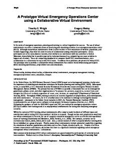
4.22 Software Tool Used Roobot System Intelligent Teaching Tool, FANU UC, RO OBOGUIDE (E E) _v06 is used d to develop virtual prototypee of staacking laminations of stator core in a turbbo-generator. The T sim mulation softw ware was used to create the virtual robot and a alsso model of other o hardwaree such circularr assembly tabble, picck up tables annd vertical colu umn. The virtuual robot was thhen proogrammed usinng the internall built in teachh pendant and run r in test mode to veerify the process [6, 7]. 4.33 Approach too the problem A virtual prototyype can be dev veloped using robot simulattion sofftware. To reacch the objectiv ve, that is to redduce the time and a cosst, the approacch is to compaare the cycle time t for differrent parrts picking, single part picckup, double part pickup and a muultiple part pickkup as: 4.33.1 Single partt pickup A single stampping is picked d up by the gripper from m a mination stacks are placed and a staationary table where the lam plaaced on another stationarry circular table where the lam minations are finally f stacked together in ann annular mannner. Thhe gripping toool used in thiss pickup is a magnetic gripper whhich holds the single laminatiion sheet. It is designed in suuch a way w that the laamination getss tightly fixed to that using the maagnetic parts atttached to the tool accordingg to the shape and a sizze of the laminnation sheet. This T process is taking a timee of 45.85 seconds foor picking and placing p each part. Main view w of thee robot enveelope and ty ypical prograam for pickking lam minations in siingle part pick kup is shown in i the Fig. 5 and a Figg. 6 respectivelly.
Fig. 6: Pro ogram for singgle part pickup p
4.3.2 Double part picckup Two paarts are picked at a time by thhe robot from thhe stationary table annd placed on thhe circular tablee one after the other on the respectiive position taught t using command. Inn the same mannerr the program is repeated unntil the stackss are placed. The griipping tool ussed here is a mechanical clamp c which holds tw wo laminationss at a time. Thhis process is taking a time of 33.100 seconds for picking p and plaacing two partss. Main view of the robot enveloope and typiccal program for picking laminattions in doublee part pickup is i shown in thhe Fig. 7 and Fig. 8 reespectively.
Journal J of Matterial Science and a Mechanicaal Engineering (JMSME) Print ISSN: 2393-9095; Online O ISSN: 23393-9109; Vollume 2, Numbeer 5; April-Junee, 2015
Deeveloping a Virttual Prototype for f Stacking Lam minations in Staator Core of Tuurbo Generator using u Robot Sim mulation Software
459
Fig. 9: Multiple parrt pickup Fig. 7: Doublle part pickup
Fig. 10: Prog gram for multiiple parts pick kup
Fig. 8: Program forr double part pickup
4.33.3 Multiple parts pickup A total t of nine sttampings are to o be placed on the circular taable andd the robot piccks all the ninee parts at a tim me and places one o aftter the other onn their respectiive positions. The T gripping tool t is made in such a way that it holds all the nine parts firm mly T is a time, energy and cost c unttil the last parrt is placed. This savving process. This process is taking a time of 19.1184 secconds for pickiing and placin ng all the nine parts. Main viiew of the robot enveelope and prog gram for pickinng laminationss in muultiple part piickup is show wn in the Fig. 9 and Fig. 10 resspectively.
5. CO ONCLUDING G REMARKS A virtuual prototype using Robott Simulation Software in stackingg stator core laminations of o a turbo-generator. For picking single part thee Robot takes much m time com mpared to the c that the time can multiplee part picking. So, it can be concluded be saveed in the multipple part pickinng which thereeby increases the rate of production. a) Timee taken to com mplete the pickking and placiing in single part pickup is 45.85 seconds, doouble part pickkup is 33.10 secoonds and in muultiple parts piickup is 19.384 seconds is show wn in the Tabble 1, where as a in manual process p it is more which depennds on the operaator.
Journal J of Matterial Science and a Mechanicaal Engineering (JMSME) Print ISSN: 2393-9095; Online O ISSN: 23393-9109; Vollume 2, Numbeer 5; April-Junee, 2015
Pradeeepthi Geddam m and Birendra Kumar K Barik
460
b) The consistenncy of the Robotic technologgy is much higher than the mannual process which can be cllearly understoood from the cyclee time. c) The manual handling h of lam mination sheetts by the workkers can be avoideed and thereby reducing risk. d) The rate of production p can n be increasedd when compaared with the manuual process.
human efforts. It will w also decreease the repettitiveness in manipuulating the physsical or real robbot.
6. AC CKNOWLEDG GEMENT I wouldd like to express my sincere gratitude to Bharat B Heavy Electriccals Limited Corporate Reesearch and Development D Divisionn, Hyderabad for providingg me valuablle source to complette this work suuccessfully.
Table 1: Tiime for differen nt number of paarts pickup
REFER RENCES Number of parts pickup Single parrt pickup Double parrt pickup Multiple paart pickup
Cycle Time (seconds) 9 stampiings – 1 layer 4 45.85 3 33.10 19.384
5.11 Comparison n between cyccle time for number n of paarts picckup In this comparisoon the time tak ken by the singgle part pickupp is muuch more than the multiple parts p pickup whhich is the keyy to fullfill the objectiive. As discusssed in the prevvious chapters the maanual process is completely y labor depenndent process,, it com mpletely depeends on the sk kill and the experience e of the robbot. It also vaaries from num mber of parts picking. So the com mparison is made m between the t cycle time for each proccess of picking. In thiis report cycle time is definedd as the total tiime takken for the robbot to pick and d place all the nine objects in a sinngle layer. Analysis between n number of parts p picking and a cyccle time are shown in the Fig g. 11.
[1] Turrbo-Generator, Wikipedia, W The free f Encyclopediia. [2] A journal publishhed on specificcation for typees of TurboGennerators. [3] Maanufacture of Turrbo-Generators in i BHEL. [4] Takken from the imaages published by b BHEL, Hyderrabad. [5] A joournal publishedd on Stacking off stator core lamiinations. [6] Robbot System Intelligent Teaching T Toool, FANUC RO OBOGUIDE. [7] Avaailability and Caapabilities of ‘L Low-End’ Virtuaal Prototyping, Pubblished by PRIM ME Faraday Parttnership, ISBN, 1-84402-0185, 2001. 2 [8] Bennnett Brumsonn, “Robotic Simulation and a Off-line From Acaademia Industry”, Proogramming: to httpp://www.robotics.org/content-deetail.cfm/Industriial- RoboticsFeaatured-Articles/R Robotic-Simulatiion-and-Off-lineeProogramming-From m-Academia-to Industry/content_ I _id/1825 [9] Du Zhijiang, Yang Donghai, Sun Lining L and Fu Lixin, L “Virtual Robbot Simulation and Monitoringg System Basedd on Java3D”, Prooceedings of thee 2004 IEEE, International Conference C on Robbotics and Bioomimetics, Sheenyang, China, p. 313-317, Auggust 2004. [10] Peddro Neto, J. Norrberto Pires, A. Paulo Moreira,, “Robot Path Sim mulation: a Low L Cost Soolution Based on CAD”, IEE EERam2010, 9788-1-4244-6506-44, 2010. [11] Siem mens, “PLM Sooftware’s Robottics Simulation: Validating & Com mmissioning thhe Virtual Worrk-cell”, ARC White Paper, Maarch 2008.
Fig. 11: Graph hical analysis
A graph is draw wn between th he number of parts p pickup and a cyccle time whicch clearly giv ves an idea why w the Robootic tecchnology playss a major role in i the process of stacking staator corre laminationss. The stacking g process usinng a robot is not cosst effective for f many smaall productionns. The Robootic Technology can be b extended in n making otherr process whichh is moore productive than other manual processees and eliminaates
Journal J of Matterial Science and a Mechanicaal Engineering (JMSME) Print ISSN: 2393-9095; Online O ISSN: 23393-9109; Vollume 2, Numbeer 5; April-Junee, 2015