Paper: ASAT-13-CT-15 th
13 International Conference on AEROSPACE SCIENCES & AVIATION TECHNOLOGY, ASAT- 13, May 26 – 28, 2009, E-Mail:
[email protected] Military Technical College, Kobry Elkobbah, Cairo, Egypt Tel : +(202) 24025292 – 24036138, Fax: +(202) 22621908
Developing Controller Performance Using Model-Based Design and Rapid Controller Prototyping Techniques A.Y. Maxi*, E.Y. Akl**, S. M. Wasfy***, S.M. Sharaf†, M.I. Ghobrial‡ Abstract: Developing a controller for a mechanical conveyor mechanics is considered in this paper. The mechanical conveyor under study is divided into two subsystems. The first is a rotating mass and the second is a chain conveyor. Each of these subsystems can operate independently from the other. Two identical servo motors supported with two similar drivers are used to drive this system. A controller is designed to achieve significant response of the system and to respond to the user demands for different modes of operations. Also, the controller achieves the required profile of the output speed for the motors. In addition, perfected following of the motors speed with the required speed trajectory for each subsystem must be ensured. This paper describes the integration among Computer Aided Design and Computer Aided Engineering CAD/CAE software, real time testing and simulation incorporated with rapid controller prototyping techniques can be used to perform controller design for complete mechatronic machine. The article and experimental results to satisfy the improved performance of the system are included in this paper. Keywords: Co-Simulation, Real-time Simulation, Rapid Control Prototyping, xPC Target Box, PI controller, Hardware in the loop.
1. Introduction Industries today face a growing need for integrating systems. Integration of mechanical, electrical and software components as well as systems into a final product. Mechatronic design simulation can reveal potential problems that may arise when these systems are integrated, allowing multiple iterations on design alternatives and a faster, and more efficient development process. Increasing the integration between controller and mechanical design has potential to shorten the design process while increasing the performance of the designed system. Furthermore,
*
Eng, Science and Technology Center of Excellency,
[email protected] Dr., Director of Technical Institute for developed Industries, El-Salam City,
[email protected] *** Prof. Dr., Dean, Faculty of Engineering-Helwan University,
[email protected] † Prof. Dr., Head of Electrical Power Engineering Department Faculty of Engineering, Helwan University,
[email protected] ‡ Prof. Dr., Head of Mechanical Engineering Department Faculty of Engineering, Helwan University,
[email protected] 1/14 **
Paper: ASAT-13-CT-15
increasing the integration between electronics, electro-mechanics and mechanical development, will likely result in systems that are more compact, lighter, more efficient and less costly. The drawbacks with independent development of the mechanical, electrical, electronic, control and software components, and late design integration are recognized in many publications, [1,2]. Nevertheless, the subject of integrated design methods is relatively unexplored. Some work has however been published, especially in the area of integrated structure/control design. It has in several scientific papers been demonstrated that the design of the structure and the design of the controller need to be integrated in order to find the system best performance, [3,4]. However, very few papers present a design methodology for fully coupled design problems, where the individual design of one component depends on the design of the other components and vice versa. Zouhaier AFFI, and Lotfi ROMDHANE [5] in their paper, they try to integrate CAE application (ADAMS) With Matlab in order to optimize the dynamic behavior of different mechanisms. A crank slider mechanism was used to illustrate this approach. Only offline simulation was carried out in this paper. In addition authors of this paper didn’t manage to verify their simulation results by implementing the proposed controller on the system. Roberto B., Silvano B.i [6], presented a rapid controller prototype using MATLAB/Simulink xPC and real time work shop integrating this tools with C++ compiler in order to generate automatic that can be run directly on a rapid prototype controller (xPC target box). The authors had not conceded the mechanical design of the system under study. So complete required integration had not been achieved. In this paper a controller is developed using model base design technique. For the verification of the capabilities of this controller a rapid controller prototype was implemented. Advanced techniques are introduced in this paper The research layout is firstly plan to draw the schedule of the required work, collect the needed data, and arranges the essential tools. In addition system identification steps are carried out in order to identify the system parameters. In this step CAD/CAE NX package is used for modeling the system and simulate it. Results from the modeling and simulation are used for designing the required controller. In this step integration between the mechanical and control design is achieved. This integration ensures that the modeling and simulation are prepared in an environment very close to the real one. Base on the real time simulation results an experimental setup process is carried out. The proposed controller is implemented using on shelf hardware Mathworks xPC Target box fitted with A/D and D/A cards. Matlab Simulink, real time work shop and GUI tool are used as a friendly readymade package for programming the xPC. Carrying out the experimental work came up with excellent results. Great agreement between the motor speed responses with the required speed trajectory is ensured. The results verify the robustness of the developed controller 2/14
Paper: ASAT-13-CT-15
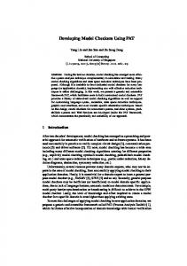
2. Research Layout A mechanical conveyor mechanism is shown in Fig. 1. It is required that to respond in a high performance to a require load profile, shown in Fig. 2, “task one”, and to undertake a number of operating modes “task two”. The mechanical conveyor under study is consists of two mechanisms. Each mechanism is driven by servo motor supported with power amplifier. A controller is required to control the response of the system and to respond to the user demands for different modes of operations.
Fig. 1 Schematic Diagram of the System
Fig. 2 Required Load Profile
The developed technique is summarized in the flow chart shown in Fig. 3. The aim of this technique is to shed light on the power of using and integrating model base design, rapid controller prototyping as powerful cost effective and efficient tool suitable to develop controller design. In the next section the proposed technique will be presented to design of a code that can operate the system under study.
Fig. 3 Planned Workflow 3/14
Paper: ASAT-13-CT-15
3. System Identification In this section CAD/CAE package “I-DEAS/NX6 package” had been used to perform system identification. Using available data, a parametric 3D model of the system component was modeled. The parametric 3D model posses in its structure all the necessary data “mass and inertia,” that will be needed in following design process. Parametric modeling is a powerful tool gives the user great flexibility to change and alter the design in an easy way. Adding 3D components with the right constrains create the system assembly which give visualization abilities, and helping the designer to navigate throughout the design checking for unwanted clearance or interference. Figure 4 shows the complete assembly of the mechanism. The upper part is the rotating mass enclosed in casing holding it between two set of bearing. While the lower is the chain container. The upper and the lower subassemblies are connected through intermediate conveyor. Simulating the motion of the mechanism is carried out using the motion simulation module in NX package. In this step, parts are converted to links with defined physical properties. Constrains to joint defining the relation between two connected links. Driver parameters, and gear relations are added. Load profiles, viscous and dry friction are applied. The motion simulation navigator shown in Fig.5 shows the mention items, also the sensors, and result containers are shown. Running the simulation, show results of the uncontrolled response of the system for the required load profile. Figure 6 shows that the system fails to respond with the required response. So a controller must be added to the system in order to achieve the required response.
Fig. 4 System Complete Assembly
4/14 Fig. 5 Motion Simulation Navigator
Paper: ASAT-13-CT-15
Require response Actual response
Fig. 6 Simulation Result of Uncontrolled Model
3. Controller Design The required controller task is to control angular velocity of the system. But NX motion simulation results show that the angular velocity of the motor needs to be controlled in order to achieve the required load profile. Proportional plus Integral (PI) controller is proposed as an effective technique in controlling DC servo motors [7]. Figure 7 shows a simplified schematic diagram of the system.
Fig. 7 Schematic Diagram of System
3.1. Mathematical Modeling The mathematical modeling of the system is carried out using the traditional way as flow. The system transfer functions are determined using Newton laws of motion and Kirchhoff's current law [7]. The transfer functions for the system under study are given below. Fig.8 shows block diagram presentation of the system which will be used in the modeling of the system. The values of the proportional and integral gains, respectively, Kp and Ki are computed using Matlab response optimization tool box.
Fig. 8 Block Diagram Representation of the System 5/14
Paper: ASAT-13-CT-15
Kt (S ) LJ V (S ) RJ FL FR K b K t S 2 S JL JL Kt ( s) LJ V ( s ) 2 RJ FL FR K b K t S S JL JL
T (S ) V (S )
(1)
1 S
(2)
Kt F S L J FR K b K t RJ FL S2 S JL JL
(3)
Table.1 illustrates the parameters of the system under study.
Table 1 Parameter R L T I V Kb Kt Ω F J Θ
Description Motor resistance Motor inductance Total Torque delivered by the motor Armature winding current Applied armature voltage Motor back EMF constant Motor Torque constant Rotor motor maximum operating speed Equivalent viscous-friction referred to the motor shaft. Equivalent moment of inertia referred to the motor shaft Angular displacement in rad.
Value 0.49 Ohm. 0.00542 H 92 N.m 11.5 A 540 V 0.99 1.67 270.31 rad/sec. 0.1997 N.m/rad/sec 0.1898 kg.m2
By substituting the value of the system parameters in the equations 1 to 3, they can be written in the following forms:
( s ) 1623 2 V ( s ) S 91.46 S 1707
(4)
(s ) 1623 V ( s ) S 3 91.46S 2 1707S
(5)
T (S ) 308.1 S + 324.2 2 V ( S ) S 91.46 S 1707
(6)
6/14
Paper: ASAT-13-CT-15
3.2. Model Simulation and Analysis Matlab Simulink capabilities are used to create the Simulink model representing the system, as shown in Fig.9.
Fig. 9 Simulink Model of the System Using PI Controller
Using the new control integration capability added to NX motion simulation, the transfer function blocks are simply replaced with NX physical block which accurately contains all the required parameters of the system. The NX physical block is introduced in Matlab Simulink model as shown in Fig.10.
Fig. 10 NX Physical Block Introduced in Matlab Simulink Model The computed controller gains of Kp and Ki are applied to the system and simulating them in NX motion simulation module while Matlab Simulink model is working in the back ground. Figure 11 shows the system response simulation with P Controller. The motor speed, motor armature current and motor voltage are listed. The results show that the proportional controller achieves a good controlling action for the transient and steady state region for angular velocity Ω. But it is not convenient for control voltage or current because of increasing Kp makes transient oscillations in current and voltage increases. To achieve the accuracy of the steady state response, damp the unwanted disturbance and decrease overshoot the integral controller is added. Figure 12 shows the results of the system with PI controller. The Figure shows that the controller parameters are seem to be efficient for this system. The current and voltage oscillations are eliminated. The best values of Kp equal to 5 and that of Ki equal to 100. These values are computed using Matlab SISOtools. The complete Simulink model can be created as shown in Fig.13. 7/14
Paper: ASAT-13-CT-15
Require and Actual responses are Identical
Oscillation
Fig. 11 System Response Simulation with P Controller Voltage and Current Oscillations Require and Actual Responses are Identical
Fig. 12 System Response with PI Controller Better Performance No Oscillations 8/14
Paper: ASAT-13-CT-15
Fig.13 Complete Model of the System
4. Rapid Controller Prototyping Experimental Setup Rapid controller prototyping techniques allow implementing and validating control strategies during the development process is performed in this section. Users can work within the same environment from the requirement analysis to the controller design and implementation phase as shown in Fig. 14. The xPC target box will be used as on shelf hardware that can be customized for control tasks. Matalab Real time workshop on the host PC will be used as a readymade package that can be used to create controller algorithm to be executed on the target box.
Fig. 14 Rapid Controller Prototyping 9/14
Paper: ASAT-13-CT-15
4.1. Rapid Controller Prototyping Architecture The xPC target host-target architecture is shown schematically in Fig. 15. On the host PC (which runs MATLAB, Simulink, Real-Time Workshop, and xPC Target), xPC target box works with the code generated from the Simulink application and a C compiler to build the real-time target application. The target application can run in real time on a target PC once it is downloaded to the target PC from the host PC. The target hardware is booted from a realtime kernel in xPC Target. However, the xPC target kernel needs the PC basic input/output system (BIOS) because when the target PC boots and the BIOS is loaded, the BIOS prepares the target PC environment for running the kernel and then starts the kernel.
Fig. 15 xPC Target Host-Target Architecture The kernel initiates the host-target communication, activates the application loader, and waits for the target application to be downloaded from the host PC. The host-target communication can occur through either serial or TCP/IP communication protocols. Once the target application has been downloaded to the target PC, it can be controlled and modified from the host PC.
4.2. Controller layout In this section a rapid controller prototype will be created to control the system under study. To achieve this goal a layout of the controller is planed, as shown in Fig.16. The layout shows that the planned controller has three levels. The first level is a data collection task in which input digital signals from operation switches are required to be logged to the system. Based on input signals combination an operation mode will be selected. For this level Matlab state flow tool will be used. In the second level, based on the selected mode, the system will have to respond to a load profile. So both the speed and position are required to be controlled. For this level the Simulink model created in the previous section will be used. The system transfer function will be replaced with a real world reference speed. Compared with speed measured from incremental encoder, the PI controller compensates the error to conserve the system stability. The third level is the hardware level. Where input signals form switches, and incremental encoders are logged into the system. Accordingly, the controller voltage Vc voltage is introduced to the motors drivers. The driver is a thyristorized amplifier generating full wave power source which is controlled by a electronic firing circuit. The firing instants of the driver thyristors are controlled by Vc. For this stage the xPC target box, fitted with D/A I/O RUBYMM-1612 Card to output Vc to the motor drivers, and in the same time acquire digital switches signals. I/O 306 Real Time Devices DM6814 card is used in acquiring incremental encoder signals and converts it to speed reading for feedback action. 10/14
Paper: ASAT-13-CT-15
Fig.16 Controller Layout Figure17 shows the experimental thyristorized amplifier developed in this study. It consists of full wave half controlled thyristorized bridge. A reliable firing circuit is built up to adjust the instants of the firing of the thyristors to achieve the required voltage for the motors and consequently the motor speed response. A freewheeling diode is used to adjust the motor operation in the first quadrant.
Fig. 17 Experimental Thyristorized Amplifier Connected to Firing Circuit and xPC 11/14
Paper: ASAT-13-CT-15
4.3. Code Design and Implementation The code is designed in Simulink environment. State flow tool is used as an easy graphic user interface (GUI) programming imply for stating the operating mode option conditions. While xPC Simulink library supports the chosen I/O card. A PI controller is used in this implementation. The parameters of Kp and Ki are applied based on the computed values from the early study. The complete model is shown in Fig.18. A Matlab GUI portal is used to design controller and runs the process. Fig.19 shows the designed GUI portal. Using Matlab Real-Time workshop the Simulink model will be build, compiled and down loaded into the xPC target. Using the GUI portal the host PC can control the running of the xPC and acquires the simulation results from it to the host PC.
Fig.18. Complete Real Time Model of the System
User Tasks User Buttons Motor 1 Speed Plotting
Motor 1 Position Plotting
Controller Tasks Display
Switches Status
Motor 2 Speed Plotting
Motor 2 Position Plotting
Fig.19 Designed Controller GUI Portal 12/14
Paper: ASAT-13-CT-15
5. Experimental Results For the experimental system the relation between the output speed (Ω) and the applied voltage (V) can was computed by comparing actual system response to reference unit step response input using Matlab System Identification Toolbox. So the transfer function of the experimental system can be written on the following form: 1.61325 2 V S 3S 2.25
(7)
While the relation between the position (Θ) and the applied voltage (V) can be written in the form of: 1.61325 3 (8) V S 3S 2 2.25S Furthermore the relation between the Torque (T) and the applied voltage can be written in the form of: T 0.306 s 0.322 (9) V S 2 3S 2.25 Using the previous developed technique experimental results are obtained from the experimental setup. The results verify the robustness of the developed controller. Several experimental tests are obtained and plotted in this section. Fig.20 shows results for a real time fast code generation technique implemented on xPC target box on the proposed system. Figure 20 (A) shows the practical system response due to a step response of the motor speed of 500 rpm. While Fig.20 (B) shows the behavior of the system due to speed tracking to the required trajectory. Great agreement between the motor speed responses with the required speed trajectory is ensured in the tests described in Fig.20 compared with that listed in Fig.21 for uncontrolled response.
(A)
(B)
Fig. 20 System Response with PI controller Kp=2.23 and Ki=3.23
13/14
Paper: ASAT-13-CT-15
(A)
(B)
Fig. 21 Uncontrolled System Response
6. Conclusions The purpose of this paper was to show the capabilities of model based design in performing mechatronic design, simulations, and implementation. Advanced design, simulation and implementation tool were also introduced. The applied technique proved to be:
A novel technique showing result to be very accurate, reliable, and in real time. A strong Matlab/Simulink co-simulation “CAE” environment could be basis for mechatronic design and analysis. Validation and visualization of the controlled system using CAD/CAE software show to be effective technique that reduced the design time and effort. Minimum time and effort were consumed through preparing both software and hardware. Rapid-Prototyping tools like xPC Target meet the needs of system engineers. Real-time simulation is required as a controller verification step. The applied technique of the developed controller can be used for either testing or operating similar mechanisms.
7. References [1] [2] [3] [4] [5] [6] [7]
Li Q. Zhang W. J., Chen L., “A Concurrent Engineering Approach for Mechatronic Systems Design”, IEEE Transactions on Mechatronics, Vol. 6, no 2, pp 161-169, 2001. Rothfuss R., Lasa M., Heinkel “Systems Engineering in the Design of Mechatronic Systems”, International Journal of Vehicle Design, Vol. 28, no 1/2/3, pp 18- 36, 2002. Beards C. F. "Engineering Vibration Analysis with Application to Control Systems" by Edward Arnold, 1998. Daniel J. B. Armando A. R."Hardware-in-the-Loop Control System Development using MATLAB and xPC" Arizona State University May 26, 2002. Zouhaier . A, L." Computer Aided Design for Dynamic Modeling and Control of Closed Loop Mechanisms" ARAS 06 International Conference, 13 - 15 June 2006. Roberto B., Silvano B.i "Rapid controller prototyping with Matlab/Simulink and Linux" University of Applied Sciences, 21 September 2004. Ogata.K. "Modern Control Engineering". Prentice Hall, fourth ed. pp 87-117, 2002.
14/14