Enterprise Modelling and Information Systems Architectures Vol. 8, No. 2, December 2013 Hanns-Alexander Dietrich, Dominic Breuker, Matthias Steinhorst, Patrick Delfmann, Jörg Becker
42
Hanns-Alexander Dietrich, Dominic Breuker, Matthias Steinhorst, Patrick Delfmann, Jörg Becker
Developing Graphical Model Editors for Meta-Modelling Tools Requirements, Conceptualisation, and Implementation Meta-modelling tools have been proposed to facilitate the development and adoption of domain-specific modelling languages (DSMLs). These languages specify a set of domain-specific concepts and assign diagrammatic representations to them. A considerable amount of work has been done to develop metamodelling tools ensuring syntactical correctness of models created with DSMLs. However, little has been published about the challenges of developing a graphical model editor for meta-modelling tools. Specifying how conceptual elements of a DSML are to be represented graphically is often cumbersome. Moreover, tools are sometimes too inflexible to handle advanced features beyond displaying static icons. Furthermore, graphical representations must be kept consistent in case of reuse in multiple, potentially integrated DSMLs. This paper’s aim is to carve out a set of requirements for graphical model editors as used in meta-modelling tools. We present a conceptual model considering these requirements. Furthermore, we discuss an exemplary software implementation of a model editor.
1
Motivation
Conceptual models are omnipresent in today’s enterprises. In business process documentation or reengineering projects, business process modelling languages are the primary means to accomplish the project’s goals (Aguilar-Savén 2004). Designing databases, either small-scale storages or full-fledged data warehouses, is another important application area of conceptual modelling (Teorey 1999). Yet another one is software engineering, where conceptual models are an indispensable tool to plan and organize development projects (Larman 2004).
(UML) (O. M. Group 2012b). As they are designed to support as many application scenarios as possible, such languages are very expressive. Yet this expressiveness comes at the cost of complexity (Erickson and Siau 2007; Muehlen et al. 2007). Furthermore, particularities of a specific application scenario might require customization, for instance, if an important feature is missing. Domain specific modelling languages (DSMLs) can be a remedy to such problems, as they allow for developing a fully customised modelling language tailored towards a specific, concrete application scenario (Frank 2011; Schmidt 2006).
For whatever purpose conceptual modelling is leveraged, there likely exists a standardised modelling language. For instance, business processes can be represented using the Business Process Model and Notation (BPMN) (White 2004), data models are often created with the Entity Relationship (ER) Notation (Chen 1976), and software is modelled using the Unified Modelling Language
There are numerous reasons why developing a DSML could be advantageous compared to a standard language. Most importantly, domain specific concepts can be represented directly within the language, which emphasises their importance. In a standard language, these concepts could either be obfuscated or not representable at all. Tailoring languages to the needs of an application scenario
Enterprise Modelling and Information Systems Architectures Vol. 8, No. 2, December 2013 Developing Graphical Model Editors for Meta-Modelling Tools
also helps getting rid of unnecessary complexity. Standard process modelling languages are sometimes criticised to be overly complex (Muehlen et al. 2007). The same holds true for UML (Erickson and Siau 2007). It could also be advantageous to customise the graphical representation of a modelling language. For instance, activities of business processes can be accompanied by various icons to ease understanding (Mendling et al. 2010). Empirical studies substantiate the claim that using DSMLs may increase performance when working with models, for example, in a software engineering context (Kosar et al. 2012). Of course, there are not only benefits but also costs associated with the decision of using a DSML (Deursen et al. 2000). Most importantly, the concepts to be incorporated into the language have to be defined. Obviously, this task can be arbitrarily complex depending on the domain under consideration. The effort could be reduced partially if existing DSMLs were available, in which case they could be used right away or modified if needed. Moreover, training employees in using a DSML further increases costs. Finally, actually implementing a conceptual language specification within modelling software is another cost driver in DSML applications. Thus, deciding whether or not to use a DSML requires careful consideration of the costs and benefits associated with either choice. With our work, we strive towards simplifying DSML implementations in order to shift the trade-off between cost and benefit to the advantage of DSMLs. The main methodology for defining DSMLs is meta-modelling. Meta-models describe the syntax of DSMLs, that is, the modelling elements a language consists of and how these elements can be combined with each other. Numerous software tools exist to support meta-model-based DSML development. Examples are the Eclipse Graphical Modeling Framework (GMF) or the Visual Studio DSL Tools (Cook et al. 2007). State of the art meta-modelling tools are applied in challenging scenarios. Domain as well as modelling experts collaboratively create a DSML prior
to a project. In case of changing requirements, they may also have to change some aspects of the DSML during the execution of the project. Maintaining consistency of models created before and after changes were made to the language or its representation can be challenging. This is particularly true for distributed modelling scenarios, which are common for large-scale projects. Keeping a central, consistent version of the DSML specification and distributing it to all modelling clients is necessary. Creating a meta-model is only one part of designing a DSML. The other is defining how models created with the language should be visualised. This includes not only simple representational decisions such as which icon should be used to visualise a certain modelling element or which type of arrow specifies a relation between two of them. Rather, it must also describe more complex aspects such as the behaviour of icons (e.g., a UML class should increase in size when methods are added to it), or implicit relationships between elements (e.g., BPMN activities contained in pools or swimlanes). Looking at existing DSML development tools, we see a shortage of tools that offer both sophisticated possibilities of designing modelling languages at modelling tool runtime and functionality to support distributed modelling. The paper works out a list of requirements for graphical model editors used in a DSML and distributed modelling context. It provides a conceptualisation of these requirements and discusses an exemplary implementation of an editor within a meta-modelling tool. In this context, distributed modelling refers to a modelling scenario where the involved people are spatially dispersed. Models as well as modelling languages are shared among users (yet models are edited by one user at a time). The model editor we present exhibits a combination of distinctive features. It allows for flexibly adapting languages and their representation not only prior to but during active tool usage, which accounts for the fact that not all requirements of a conceptual modelling project may be known upfront. It ensures all users are
43
Enterprise Modelling and Information Systems Architectures Vol. 8, No. 2, December 2013 Hanns-Alexander Dietrich, Dominic Breuker, Matthias Steinhorst, Patrick Delfmann, Jörg Becker
44
working on the most recent version of a language specification. Furthermore, it allows for complex behaviour in modelling element representation but does not fall short in user-friendliness (i.e., does not require programming skills to define this behaviour). Practitioners as well as researchers benefit from this paper as it demonstrates how to develop a graphical model editor for metamodelling tools with advanced representational capabilities while maintaining opportunities for flexible modelling language deployment at modelling tool runtime as well as ease of use. While we believe our results are most useful in the field of domain specific modelling, the concepts are more general than that. Any other graphical modelling language, including standard notations, can be implemented as well. This could be particularly useful if sticking to some standard notation is required, yet subtle modifications are still desired. The remainder of the paper is organised as follows. In Section 2, we define capabilities for a graphical model editor supporting distributed modelling. We conduct a literature review and survey existing software tools with respect to these capabilities. In Section 3, we introduce a conceptual model of a meta-modelling tool to provide the background necessary to understand subsequent sections of this paper. Section 4 describes requirements for a graphical model editor, which are then conceptualised in Section 5. An exemplary implementation following this conceptualisation is provided in Section 6. Section 7 illustrates an application example for specifying and using a modelling language. We conclude the paper in Section 8 by summarizing our main contributions, elaborating on limitations of our approach, and providing an outlook to future research.
2 2.1
Modelling Tool Capabilities Capability Definition
Graphical modelling is done for numerous different reasons. There is an abundance of business
process modelling languages such as BPMN, Petri Nets, Event-driven process chains, and many more. Surveys of these languages can be found in Aguilar-Savén (2004) and Mili et al. (2010). More generally, there are several other languages for modelling Information Systems. These include Data Flow Diagrams (DFD), ER Diagrams, the Integrated Definition of Function Modelling (IDEF), UML, and others. See Giaglis (2001) or Shen et al. (2004) for surveys in this area. Additionally, there are popular enterprise modelling frameworks like the Multi-Perspective Enterprise Modelling (MEMO) framework (Frank 2002), the Zachman framework (Zachman 1987), the Architecture of Integrated Information Systems (ARIS) (Scheer 2000), or Archimate (T. O. Group 2009), which all provide a number of modelling languages. Below, we synthetize generic capabilities a graphical modelling editor should have in order to allow for defining arbitrary languages, in style similar to those mentioned above. They stem partly from these modelling languages, but also from the fact that a distributed (meta-) modelling scenario should be supported. In defining the capabilities, we restrict ourselves to representational aspects of graphical modelling languages used within the domain of enterprise modelling. The capabilities thus reflect the set of features a model editor has to offer to allow for flexibly and conveniently drawing a model graph and providing these graphs to users. Other capabilities exist, yet are out of the scope of this paper. First, modelling editors can differ with respect to support for specification of modelling languages at runtime (Capability C1: specification at run-time). This means that the user of the meta-modelling tool is able to specify her own modelling language at tool runtime as opposed to being forced to recompile the editor. This is usually achieved by providing a meta-meta language that allows for creating the meta-model of the newly created language (cf. Section 3 for more details). Such a capability can be important since without it, distributing updates of conceptual
Enterprise Modelling and Information Systems Architectures Vol. 8, No. 2, December 2013 Developing Graphical Model Editors for Meta-Modelling Tools
and representational specifications of languages requires recompiling (parts of) the modelling tool’s code and thus distributing updates among all clients. Another aspect is whether the model editor supports multiple different languages instead of only a single DSML (Capability C2: multiple languages). Lack of this functionality means distributing a separate model editor among users for each language and may hamper language integration. To allow for domain- or user-specific representations of a language’s elements, tools must offer functionality to design these representations, meaning the concrete syntax. Offering an editor dedicated to designing representations of languages can be important to facilitate rapid language development even if the designer is not particularly technically skilled (Capability C3: editor for representations). Regarding the functionality in terms of behaviour and appearance of model representations, several capabilities can be identified. First and foremost, graphical languages are typically represented using symbols. This is why selecting and customizing these symbols is an essential task of language design. The flexibility of a model editor with respect to defining symbols largely determines its usefulness, but also ease of use is an important factor (Capability C4: customizability of symbols). To express relationships between the symbols, edges must be supported as well. For those, the same as for the symbols applies. They have to be customisable to meet the requirements of the language that shall be supported. For instance, a choice between using solid lines for one type of edge and dashed lines for another could be made (Capability C5: customizability of edges). Edges can also be combined with symbols to even customise the edge’s start and end points (Criterion C6: customizability of edge symbols). Not all relationships have to be represented by edges. Some may arise simply from the relative positioning of two symbols, or by definition
of the language itself. While at first sight, no visualisation appears to be a model editor functionality that is straightforward to implement, documenting these relationships is in fact an important feature. In case that any reports should be made based on models, having access to implicit relationships is vital to access necessary information (Capability C7: implicit relationships). The importance of the distinction between relating symbols through visible edges attached to specified connection points and relating them through relative positioning is further emphasised by the fact that frameworks for classifying visual languages use it as one of the main dimensions to distinguish languages (Costagliola et al. 2002). The final capability is supporting distributed modelling via shared repositories of models and DSMLs (Capability C8: shared repositories). Having a centralised, consolidated repository of models instead of, for example, distributed flat-file storage facilitates distributed modelling and makes it easier to maintain a consistent state.
2.2
Search Strategy
In this section, we describe the search strategy we employed to search for relevant tools. We conducted a literature review to identify scholarly research in the field of graphical modelling editors. Our review consists of two parts. First, we conducted a structured keyword search using Google-Scholar to ensure a certain breath necessary to cover this highly multidisciplinary field. Second, we also conducted an unstructured literature review based on the body of knowledge we knew from prior experience. As for the scope of this literature review, it is important to emphasize that we were interested in meta-modelling tools that provide visual languages designed to support enterprise modelling scenarios (process modelling, data modelling, etc.). In particular, we were interested in the graphical model editors of such tools. Consequently, any graphical modelling research related to different fields, let it be cellular biology, machine learning, or image processing, has not been analysed.
45
Enterprise Modelling and Information Systems Architectures Vol. 8, No. 2, December 2013 Enterprise Modelling and Delfmann, Information Systems Architectures Hanns-Alexander Dietrich, Dominic Breuker, Matthias Steinhorst, Patrick Jörg Becker
46
Vol. X, No. X, Month 200X Anonymised
4
Capability Product [Source]
C1: C2: C3: Spec. at Multiple Editor for run-time languages rep.
C4: Cust. of symbols
C5: C6: C7: Cust. of Cust. of Implicit edges edge sym. rel.
C8: Shared repository
ADONIS (Junginger et al. 2000)
—
X
—
B
B
B
—
X
ARIS (Davis 2008; Scheer 2000)
(X)
X
X
B
B
B
—
X
AToM3 (Lara and Vangheluwe 2002, 2004)
—
X
—
B
B
B
—
X
DIAGEN (Minas 2002)
—
—
—
A
A
A
—
—
DIAMETA (Minas 2006)
—
—
—
A
A
A
—
—
DOME (Engstrom and Krueger 2000)
—
—
—
B
B
B
—
—
EuGENia (Kolovos et al. 2009)
—
—
—
A
A
A
X
—
GEMS (J. White et al. 2007)
—
—
(X)
C
B
B
—
—
GenEd (Haarslev and Wessel 1996)
—
X
—
B
B
B
X
X
GenGed (Bardohl 2002; Bardohl and Ehrig 2000)
—
X
X
B
B
B
—
X
GME (Ledeczi et al. 2001)
X
X
—
A
A
A
—
—
GMF (The Eclipse Graphical Modeling Framework (GMF) 2012)
—
—
—
A
A
A
X
—
GraMMI (Sapia et al. 2000)
X
X
—
A
A
A
—
X
JComposer (J. C. Grundy et al. 1998)
—
—
—
B
B
B
—
—
Marama (J. Grundy, Hosking, Huh, et al. 2008; J. Grundy, Hosking, Zhu, et al. 2006)
X
X
X
B
B
B
X
—
MetaEdit+ Ver. 4 (Tolvanen and Rossi 2003)
X
X
X
B
B
B
—
X
Moses (Esser and Janneck 2001)
X
X
—
A
A
A
—
—
PDE (Kuhrmann 2011)
—
—
(X)
A
B
B
X
—
Pounamu (Zhu et al. 2007)
X
X
X
B
B
B
—
—
TIGER (Ermel et al. 2006)
—
—
X
B
B
B
—
—
VisPro (Zhang et al. 2001)
—
X
—
A
A
A
—
—
VMTS (Mészáros et al. 2008)
—
X
(X)
A
A
A
X
—
VS DSLT (Cook et al. 2007)
—
—
—
A
B
B
X
—
Requirements
R4
R14
R15
R3
R3, R5
R3, R5
R9, R10
R13
Table 1: Capabilities of domain-specific modelling or meta-modelling tools
Table 1: Capabilities of domain-specific modelling or meta-modelling tools The final capability is supporting distributed modelling via shared repositories of models and DSMLs (Capability C8: shared repositories). Having a centralised, consolidated repository of models instead of, for example, distributed flat-file storage facili-
tates distributed modelling and makes it easier to maintain a consistent state.
2.2
Search Strategy
In this section, we describe the search strategy we employed to search for relevant tools. We conducted
Enterprise Modelling and Information Systems Architectures Vol. 8, No. 2, December 2013 Developing Graphical Model Editors for Meta-Modelling Tools
To conduct the keyword search, we defined two classes of terms. The first class contains the terms ‘tool’ and ‘editor’. The second class contains the terms ‘visual language’, ‘visual notation’, ‘graphical model’, ‘meta modelling’, ‘enterprise modelling’ and ‘domain specific’. We combined each term of the first class with each term of the second class, resulting in a total of 12 keywords that we entered into Google Scholar. For each keyword, we considered the first 30 hits. Out of these results we selected those papers published in peer-reviewed journals and conference proceedings. We did not consider monographs or links to websites. The resulting set of papers was analysed with respect to whether the tools they describe fulfil the capabilities introduced above. This narrowed down the set of papers to a selection of 27 papers representing 15 unique tools. We did not consider papers describing visual languages that cannot be used in the context of enterprise modelling. Examples of such work include papers on visual languages for biology networks, image processing, and education. We also excluded papers that contain a particular modelling language, modelling framework, or language exchange format without presenting an according implementation within a graphical model editor. This also includes any kind of modelling tool with no functionality to specify languages. Furthermore, we did not consider papers presenting model analysis approaches. Examples of such work include, for instance, approaches to check UML diagrams for consistency. We added eight tools we knew to be related to the resulting set of 15 tools and also included them in the following tool survey.
2.3
Tool Survey
In this section, we evaluate the current state of the art of 23 meta- and domain specific modelling tools for enterprise modelling against the backdrop of the capabilities introduced above. We demonstrate that while all tools satisfy some of the capabilities, none of the tools provides comprehensive support for all of them. For reasons of
brevity, we will restrict ourselves to a detailed description of those tools that are most prominent in our opinion. The appendix contains more information on the exact classification of each tool. In Tab. 1, all 23 tools are listed and compared with respect to the capabilities. For capabilities C1, C2, C3, C7 and C8, an ‘X’ indicates that the corresponding features as described in the previous section are available. We write ‘–’ in case of the opposite. As special cases, capability C1 is ranked ‘(X)’ if languages technically can be added at run-time, but no user support is given to define one, and capability C3 is ranked ‘(X)’ if an editor exists but is a 3rd party editor that could be attached to the tool. For capabilities C4, C5 and C6, presence or absence cannot be judged that easily. Therefore, we decided to rank them with respect to three different categories ‘A’, ‘B’, or ‘C’, with decreasing degree of support for the corresponding capability. For capabilities C4 and C6, which are those related to symbols, we applied the following scheme: A tool is rated ‘A’ (= high) when it allows virtually all conceivable adaptations. For example, this is true if programming languages or GUI frameworks are used. It is rated ‘B’ if a set of visual primitives (e.g., lines and rectangles) are composed declaratively to define the representation. We assign rating ‘C’ if static pictures are used. For capability C5, which relates to edges, we applied the following scheme: Rating ‘A’ means that everything is customizable by programming languages with a wide range of functionality. We rate ‘B’ if a predefined set of properties exists from which the user can choose. Category ‘C’ means no support for edge customisation (but no tool has been scored ‘C’). While aggregated results of tools and their capabilities can be found in Tab. 1, we provide detailed information on each rating in the appendix in Tables 2 to 24.
47
48
Enterprise Modelling and Information Systems Architectures Vol. 8, No. 2, December 2013 Hanns-Alexander Dietrich, Dominic Breuker, Matthias Steinhorst, Patrick Delfmann, Jörg Becker
The first tool we evaluated is the Eclipse Graphical Modeling Framework (GMF). It is a tool supporting the creation of graphical model editors and modelling languages and allows for generating source code out of a graphical model. It is built on the Eclipse Modelling Framework (EMF) and the Graphical Editor Framework (GEF), to which it adds a layer of abstraction on top. The EMF provides basic classes for representing models, their serialisation and model constraint checking. In combination with GEF and Draw2D, models can be visualised. Draw2D provides layout and rendering features for model elements and adds an event propagation system for changes and repaint operations. Visualisations are composed of predefined, basic elements (e.g., rectangles) from Draw2D, which are mapped to meta-model elements. Advanced visualisation elements require customised implementations. Thus, knowledge of low-level procedural programming is required. Another Eclipse-based tool is the Generic Eclipse Modelling System (GEMS). It is designed to support rapid development of graphical modelling tools (White et al. 2007). Icons (pictures) are used to visualise modelling elements. They are customised with Cascading Style Sheets (CSS). Similar to GMF, TIGER supports generating graphical model editors from a meta-model. It is also based on EMF and GEF (Ermel et al. 2006). Model element visualisations are specified using a visual editor. This results in ease of use, which comes at the cost of flexibility though. The elements are closely related to GEF elements. Unlike the tools discussed above, visualisations are specified in the meta-model and are not hard-wired into the modelling tools compiled from it. Microsoft Visual Studios DSL Tools (VS DSLT) is another tool for DSML design (Cook et al. 2007). Like in GMF, generating a graphical model editor’s source code is done according to a meta-model. After compilation, the modelling tool is integrated into Visual Studio as a plugin. Visualisation of modelling elements can only be modified by procedural programming.
Kuhrmann (2011) developed a meta-modelling tool called Process Development Environment (PDE). It is based upon Microsoft’s DSL Tools and mainly adds a new graphical model editor on top of it. The editor analyses a DSML and creates corresponding generic templates. The templates are based on the Extensible Application Markup Language (XAML), with which GUIs can be described declaratively. This external document can then be modified using a software assistant. Thus, the user is assisted while modifying the visualisation, but is still required to possess a fair amount of technical understanding to work with the XAML code. MetaEdit+ is another DSML tool primarily developed to support automatic code generation (Tolvanen and Rossi 2003). The MetaEdit+ workbench allows for creating modelling languages with an assistant or graphically with its own modelling language. All DSMLs can be loaded from a shared repository into the MetaEdit+ Modeller in order to use them for modelling. Yet another meta-modelling tool is the Generic Modelling Environment (GME) (Ledeczi et al. 2001). It uses the UML class diagram notation for meta-model definition. More complex rules can be specified with Object Constraint Language (OCL) expressions. Again, programming is required to modify the way models are visualised. A modelling tool extensively used in practice is the ARIS Business Architect & Designer (Scheer 2000). It has a predefined set of over 200 modelling languages (Davis 2008). The visual appearance of the modelling language elements can be changed with an editor. Specifying a new modelling language from scratch is not possible for ordinary ARIS users. They either have to be implemented by procedural programming or can be imported. Mészáros et al. (2008) designed an approach similar to the graphical model editor presented in this paper. It is called the Visual Modelling and Transformation System (VMTS) and is based on XAML. The authors use plugins which can be mapped to (meta-) models in order to specify
Enterprise Modelling and Information Systems Architectures Vol. 8, No. 2, December 2013 Developing Graphical Model Editors for Meta-Modelling Tools
the appearance of model elements. Therefore, the appearance specification is stored separately in XAML-files and can thus be edited by users without recompiling code. Still, the user has to restart VMTS. Pounamu (Grundy et al. 2006, 2008) is a further meta-modelling tool that allows for specifying modelling languages without recompiling the tool. The model editor incorporated into the tool is capable of displaying models of all languages that have been previously defined. The tool also includes an editor for designing visual representations of language elements. The user can choose from a predefined set of properties to customize and display symbols, edges, and edge symbols. Based on the literature we reviewed, the tool is not capable of defining implicit relationships between language elements and does not store models and languages in a shared repository. AToM3 (Lara and Vangheluwe 2002, 2004) is a meta-modelling tool that provides a model editor capable of displaying models developed in all languages defined in the tool. Predefined visual primitives are available to display symbols, edges, as well as edge symbols. Models and languages are stored in a shared repository thus facilitating distributed modelling scenarios. The modelling environment requires recompilation of the modelling language definition if changes are being made to the modelling language and a restart if representations are changed. An editor for designing representations is also not available. Moses (Esser and Janneck 2001) is a meta-modelling tool that allows for specifying and subsequently using modelling languages without recompiling the code. The model editor is capable of displaying models developed in the previously defined languages. Programming symbols, edges, as well as edge symbols provides utmost flexibility. The tool does not contain an editor for representations and does not allow for defining implicit relationships between language elements. Models and languages are stored in separate repositories.
Table 1 demonstrates that all meta-modelling tools we evaluated have their strengths, but a tool supporting comprehensive support for all of our capabilities at the same time is lacking. Tools such as GMF, GME, or VS DSLT offer extensive functionality and great flexibility, but cannot be called particularly user-friendly. Users who are not technically skilled cannot be expected to make use of all this functionality. Other tools such as ARIS are more accessible for non-technical users, but offer less flexibility with respect to the graphical representation of models. The conceptualisation of a graphical model editor presented in this paper is meant to be a step towards closing this research gap. It aims at offering an environment with sufficient flexibility for the representation of advanced language constructs while maintaining ease of use by avoiding the necessity for programming.
3
A Conceptual Model of a Meta-Modelling Tool
To define the basic modelling language elements and to support the creation of a common ground (Clark 1996), we first present the meta-meta-model with which we specify languages. This model provides the basis for supporting capabilities C1 and C2. It is also means to implement a shared repository for both languages and their models (C8). Databases or repositories of modelling tools are used to store all relevant model data, meaning all model elements, relationships, attributes, etc. A typical way of designing such databases is implementing meta-models of supported modelling languages directly. This means that for each modelling language the corresponding meta-model is directly created in the database or, more precisely, the meta-model elements are transformed into database tables. However, a meta-modelling tool has to provide functionality for modelling language design at run-time. The user of the tool should thus be able to specify a modelling language without changing the implementation of the modelling tool. Designing a meta-modelling tool’s database in the ‘conventional’ modelling
49
Enterprise Modelling and Information Systems Architectures Vol. 8, No. 2, December 2013 Hanns-Alexander Dietrich, Dominic Breuker, Matthias Steinhorst, Patrick Delfmann, Jörg Becker
50
(1,1)
Meta-meta-model
SourceRole multiplicity
Role
(0,n)
(0,n)
(1,1)
(1,n)
TargetRole multiplicity
(1,1)
RelationshipType Language
(0,n)
Vocabulary
(1,n)
ElementType
(0,n)
directed
D,T
(0,n)
domain
ObjectType (0,1)
Inheritance
(0,n)
Meta-model (1,1) (0,n)
(1,1)
D,T
Element
Object
value
(1,1) (0,n) (0,n)
Element Occurrence
D,T
(1,1) (0,n) (0,n)
Relationship Occurrence
Relationship Target Element
(1,1)
Target Occurrence
(1,1)
Source Element
(1,1)
(1,1)
Source Occurrence
(0,n)
Project
Object Occurrence
(0,n) (0,n)
(1,1)
Model
(1,1)
Figure 1: Meta-meta-model of the modelling environment
tool manner would require generating and/or altering database schemas dynamically (at runtime of the modelling tool), as changes to meta-models would translate to changes of database schemas. To avoid this, we use a generic data model capable of storing all sorts of meta-models (i.e., languages) and their corresponding models (i.e., models created with these languages). Consequently, this data model integrates both a meta-meta-model enabling users to specify modelling languages (i.e., the instances of the meta-meta-model, namely the particular language-related meta-models) and a meta-model storing the models (i.e., the instances of the meta-model, namely the particular models). Both sections are related, meaning that all model
elements (e.g., a task ‘place order’) can be assigned to their element type (e.g., ‘BPMN task’). This rationale implies that the tool we are proposing here does not contain a graphical meta-language that a language designer can use to create meta-models. Instead, the meta-metamodel is defined by the tool’s database structure (cf. upper part of Fig. 1). This means, that a modelling language is not created by modelling its meta-model using a graphical meta-language like, for instance, ERM or UML class diagrams. Instead, the language designer creates all basic language constructs constituting the language’s syntax by filling in forms, which are then stored in the database. We call the basic construct that
Enterprise Modelling and Information Systems Architectures Vol. 8, No. 2, December 2013 Developing Graphical Model Editors for Meta-Modelling Tools
all modelling languages consist of an ElementType (cf. Fig. 1). It represents any atomic part of a modelling language. Element types represent the abstract syntax and via their names also the semantics of the modelling language constructs (Frank and Prasse 1997). Element types can be split into constitutional vertex types (e.g., ‘ERM Entity Type’), called ObjectType, and the edge types between them, called RelationshipType (e.g., ‘EPC control flow’). A further important part of modelling languages is attributes. Attributes describe specific characteristics associated with an object or relationship. Our tool includes attribute types that can be assigned to object types and relationship types. Normally, attribute types represent artefacts being existentially dependent on their associated object types or relationship types (i.e., they are assigned 1 : 1 to object types or relationship types, e.g., in case of a caption). In order to provide a more flexible way to assign attribute types to object types or relationship types, we allow different kinds of assignment multiplicities. This means that, for instance, we can assign an attribute of the same type more than once to an object or relationship and, in addition, also delete an attribute (not only its value) during the modelling process (like, e.g., when adding or deleting multiple comments or descriptions). This way, attributes behave similarly to objects. Consequently, we regard attribute types as special kinds of object types that do not have a graphical vertex representation in the model editor. To differentiate between object types representing attribute types and ‘regular’ object types we introduce the concept of a domain. Each object type has a domain that specifies its data type (e.g., String or Integer). If the domain is set to null, the object type represents a ‘regular’ object type. If the domain carries a value, the corresponding object type represents an attribute type. In this case, an attribute that instantiates this attribute type does not have a graphical representation. Instead, it is displayed in an attribute editor of the assigned visual model element.
In order to define attribute types or relationship types only once for multiple object types, an object type can inherit from a super object type. The relationship type is associated with both a source and target element type, which are the two element types it can connect (e.g., the edge between an ERM Entity Type and an ERM Relationship Type). Additionally, a relationship type defines the assignment of an attribute type to an element type (e.g., the multiplicity attribute type of an ERM edge type). In some modelling languages, element types can adopt different roles, depending on the context in which they are used (e.g., the ERM relational entity type can be used as an ERM relationship type, to which only ERM entity types can connect, and as an ERM entity type, to which only ERM relationship types can connect). This requires specifying different Roles of element types. To facilitate reusability, roles are not directly associated with the element type. Rather, they are assigned to a construct called Vocabulary. The vocabulary specifies the modelling Languages an element type belongs to. This way, it is possible to reuse element types in different modelling languages. Furthermore, this allows for specifying different roles an element type may assume depending on the language (e.g., a relational entity type has two different roles when used in an ERM (see above), but has only one role when used as a data resource annotation in a BPMN model). As already stated, roles define the way element types can be connected by edges and links. Consequently, relationship types always start from a Source element type’s role and lead to a Target element type’s role. Source and target define the direction of a relationship type. In addition, the number of relations a source or target can participate in is defined by the multiplicity (e.g., 0 : 1 or 0 : n). In order to also define undirected relationship types, the relationship type has an attribute directed, which is either TRUE or FALSE. In the latter case, the direction of a corresponding relationship is ignored. Furthermore, the fact that
51
52
Enterprise Modelling and Information Systems Architectures Vol. 8, No. 2, December 2013 Hanns-Alexander Dietrich, Dominic Breuker, Matthias Steinhorst, Patrick Delfmann, Jörg Becker
roles are assigned to element types rather than object types makes it possible to define relationship types that connect other relationship types (like it is done, e.g., when connecting association classes to association edges in UML Class Diagrams). Once defined, a modelling language can be used to create models. This is why a particular Model always belongs to a modelling language. In other words, a model is an instance of a modelling language. Analogously, each particular model Element belongs to a certain element type, meaning it is instantiated from its element type. Model elements further belong to a modelling Project, which contains all the models necessary to describe, for instance, the business processes and data structures of a company. Elements are specialised as Objects (e.g., a particular activity named ‘place order’, or a particular attribute named ‘name’) and Relationships (e.g., a particular edge connecting an activity and an associated organisational unit), structurally equivalent to the according language definition. Accordingly, each Relationship originates from a Source element and leads to a Target element. The roles a relationship can connect to and the information whether or not it is directed are taken from the language specification. Objects can take values in case of attributes that comply with the domain defined through their object types. For example, an object named ‘name’ may carry a value ‘place order’ of the domain ‘String’. This object, in turn, may be associated with another object of the type ‘activity’ carrying no value. The business logic of the tool ensures that the modeller can only draw objects and relationships that have corresponding object and relationship types. This means, for instance, that once the modeller connects two objects with one another, the business logic determines if there is a corresponding relationship type that connects the corresponding object types. This is achieved by querying the RelationshipType table. If such a relationship type exists, the relationship is drawn
in the model editor. If it does not, the modeller is informed that there exists no corresponding type for the relationship she is trying to draw. If there are multiple relationship types defined for any two object types, the modeller has to select the type belonging to the particular relationship. In doing so, the tool ensures that the model actually confirms to the syntactical constraints defined by its language. To allow for reusing elements within a modelling project, for instance, for reusing an entity type as a resource in a BPMN model that was originally defined in an ERM, we introduce the ElementOccurrence. Occurrences inherit all the attributes associated by multiplicity (1 : 1) (i.e., attributes existentially dependent on their assigned element) with their definition. Every occurrence originates from an element definition and can be reused in different models. ObjectOccurrences and RelationshipOccurrences are defined structurally analogous to elements, objects and relationships as well as element types, object types and relationship types. In comparison to other meta-meta-models using the framework of Kern et al. (2011), the presented meta-meta-model is comparable to the meta-metamodel of GME (Ledeczi et al. 2001). In contrast to GME the presented model does not incorporate the Port concept, which defines additional constraints on how objects can be connected. Such constraints translate to larger model sections that have to be or may not be included in the overall model graph. These constraints thus go beyond defining relationships between adjacent objects. As such constraints can most easily be defined and verified using a pattern matching approach, our meta-modelling tool contains a respective mechanism (Bräuer et al. 2013; Delfmann et al. 2010; Dietrich et al. 2011). As pattern matching, however, is out of the scope of the paper at hand, we did not include our pattern matching approach here. Another possibility to define and check more advanced syntactical constraints is using the Object Constraint Language (OCL) (O. M. Group 2012a). In contrast to GME, our meta-meta-model
Enterprise Modelling and Information Systems Architectures Vol. 8, No. 2, December 2013 Developing Graphical Model Editors for Meta-Modelling Tools
allows to assign multiple attributes to an object depending on the multiplicities of the relationship type. A further difference to GME is that our model only allows inheritance from a single super object. This conceptual model of a meta-modelling tool could also be extended to support model perspectives, which allow customizing models for different user groups (e.g., variants of the graphical language notation). This extension is described in Delfmann et al. (2008), but as we want to concentrate on the core functionalities of a graphical model editor, it is not presented here. The presented conceptual model of a meta-modelling tool defines the data model to store all relevant model and modelling language data. Therefore, it can be seen as a shared repository (cf. C8), allowing to define multiple modelling languages (C2) and to instantiate these languages at modelling tool runtime (C1). To visualise models based on these specifications, a meta-modelling tool has to incorporate corresponding representational mechanisms. In the following, we derive requirements to be met by such mechanisms.
4
Graphical Model Editor Requirements
Below, we synthetize generic requirements a graphical modelling editor should fulfil in order to allow for defining arbitrary languages, in style similar to those mentioned in the beginning of Section 2. They stem partly from these modelling languages, from the literature of visual languages (Costagliola et al. 2002), but also from the fact that a distributed meta-modelling scenario should be supported. Thus, the capabilities of Tab. 1 are reflected in them. The basic requirement of a graphical model editor is to visualise the elements of a modelling language. Therefore, a 2D coordinate system is necessary (R1) (Costagliola et al. 2002). In the following, we call it the model canvas. Any graphical representation needs a position on this canvas, meaning some coordinates indicating where it is located (R2) (Costagliola et al. 2002). Each element
of a modelling language has its own graphical representation (R3). This requirement relates to C4, C5 and C6 of Tab. 1, because it provides the basic functionality for the customizability of edge and vertex symbols. To account for modelling tool runtime specification capabilities, the graphical representation has to be configurable even after the meta-modelling tool’s source code has been compiled (R4 , relates to C1). Therefore, it has to be importable and storable (serialisable). All graphical modelling languages either use a visible or invisible (implicit) relation to establish the connection between modelling elements (Costagliola et al. 2002). The easiest way to represent visible relations is to use edges between elements and provide them with different looks for easy distinction (R5, relates to C5 and C6) (cf. e.g., Fig. 3). Thus, an edge needs a start and end location specifying where it is attached to the elements it connects (R6) (Costagliola et al. 2002). Visible edges also have a path on the model canvas (R7) (Costagliola et al. 2002). The path describes the way that is taken from its start to end point. To support proper routing of edges, an interface to graph layout algorithms is vital (R8). For instance, drawing huge, complicated models such that edges do not cross can facilitate model understanding (Himsolt 1995). Also, certain flow layouts such as top to bottom or left to right could be of use, for example, to indicate the flow of time in process models. Implicit relationships between elements must be specifiable based on the relative position of elements to each other (R9, relates to C7) (cf. the package Graphical Model Editor in Fig. 4) (Costagliola et al. 2002). Properly documenting implicit relationships is especially important if reports of any kind are to be created based on the model, as the model could not be interpreted correctly with these associations missing. Therefore, explicitly supporting the documentation of implicit relations within the data model instead of leaving the relation truly implicit (i.e., only visible through relative positions and sizes
53
Enterprise Modelling and Information Systems Architectures Vol. 8, No. 2, December 2013 Hanns-Alexander Dietrich, Dominic Breuker, Matthias Steinhorst, Patrick Delfmann, Jörg Becker
54
as specified by a modeller) is an important requirement. Furthermore, when establishing such implicit relationships the element that should contain another one should automatically adapt to the size of its content or support manual size modifications (R10) (e.g., a UML class should grow when methods are added to it). Some of the graphical representations need labels to further describe the modelling language elements (R11) (Costagliola et al. 2002). Consequently, specification of labels and their value domains is a necessary requirement. To assist the user during modelling, the engine should provide certain standard functionality (R12) which could be a mechanism to align model elements, to scroll through the model canvas, or to zoom in and out. Other such functionality could be model export and printing. In contrast to modelling tools with a predefined set of representations, a meta-modelling tool can configure the representation of each model element. Therefore, it is necessary to integrate the representational aspects into the data model of the tool (cf. section 3) and thereby to enable the distribution of the representations by this shared repository (R13, relates to C8). The representation of model elements should be reusable in other modelling languages (R14, relates to C2). To design the representations of modelling language elements, a user-friendly tool (e.g., a wizard) is necessary (R15, relates to C3).
5
Concept of a Graphical Model Editor
As explained in the last section, integrating representational aspects into the tool’s data model is crucial if the representation of a language should be decoupled from the language itself (e.g., for reuse in other languages). Following best practices in software development (Fowler 2002), we decided to split functionality for data management and visualisation. Therefore, we first describe the representational parts (data management) and proceed with model visualisation parts (visualisation) as well as the connections between the former and the latter.
5.1
Data Management
Figure 2 depicts an excerpt of the extended data model of the tool. Any grey-shaded element is introduced to address one or more of the requirements discussed in Section 4. All remaining elements are those introduced in Section 3, defining the abstract syntax in the meta-meta-model. As the aforementioned requirements specify the graphical representation of the language elements and depend on the abstract syntax, the newly introduced elements define the concrete syntax (Frank and Prasse 1997). For each vocabulary, a Representation is defined by the VocabularyRepresentation relation, which allows for reusing representations in different languages (R14). A representation defines how an element type instance is represented according to a language. This could either be a graphical visualisation as a VertexRepresentation or EdgeRepresentation, or a non-graphical one as AttributeRepresentations used for attribute types, AttributeEdgeRepresentation used for the edge types connecting attribute types or ImplicitEdge-Representation for implicit relationships (here, the business logic checks that only valid relations between a representation subtype and a vocabulary and its corresponding element type can be defined). An attribute representation is not represented by any sort of icon on the drawing canvas, but is represented, for instance, in a menu that can be opened via a right-click on the associated vertex object (e.g., a process activity (vertex) can be assigned to one or more comments as attributes (via menu)). Attribute edges relate attribute objects to other objects. Implicit edges are used whenever the relationship of two objects is set up according to their mutual spatial position (e.g., when relating process activities to swimlanes). A VertexRepresentation or EdgeRepresentation defines what the graphical visualisation of elements look like and how they behave (R3, R4, R5). A specification of such a representation itself can be conceptualised as a meta-model (cf., e.g., Domokos and Varró 2002), consisting, for instance,
Enterprise Modelling and Information Systems Architectures Vol. 8, No. 2, December 2013 Developing Graphical Model Editors for Meta-Modelling Tools
55
Meta-meta-model
Meta-model
(0,n)
Language
Vocabulary
(1,n)
ElementType
Role
Object Occurrence
(0,n)
postition
(0,n)
(1,1)
Relationship Occurrence
Representational aspects
(0,n)
path
(0,1) (0,1) (1,1)
DropZone
(0,n)
Representation
(0,n)
Vocabulary Representation
(0,n) (0,n) (1,1)
object
ConnectionPoint
(0,n) (0,n)
D,T
Graphical Representation
Non-graphical Representation
D,T
Vertex Representation
Source Connection Point
Target Connection Point
Edge Representation
Figure 2: Excerpt of the extended meta-meta-model and meta-model
of lines, circles, rectangles and the like. Explicitly defining such a meta-model is not a good idea though. Any changes or new, unforeseen requirements could potentially entail the necessity for drastic changes to a low level drawing engine based on this meta-model. To account for steadily changing visualisation technology, we abstain from defining any such meta-model ourselves. Rather, we decided to store an object (of the type Binary Large Object (BLOB)) in the Representation, which can be used to store the information required by the visualisation technology in use. Support for user-friendly editing of representations is of course interdependent with the chosen technology. How to accomplish this without burdening a user with programming tasks will be discussed in Section 6. A VocabularyRepresentation consists of a symbolic representation (R3, R4, R5), connection points (R6) and so-called drop zones (R9). Connection points are those points edges can be attached to. The ConnectionPoint entity could either represent a distinctive point on the symbol’s geometry or
alternatively a complete geometry itself (line, circle, etc.) (Costagliola et al. 2002). While the latter alternative can have several advantages such as allowing a layout algorithm to choose the particular endpoint on the symbol itself, we have chosen the first one instead. It is easier to implement and the additional complexity is in our opinion not worth the effort. To allow for implicit relations (R9) we introduce areas called DropZones, which allow dropping a model element into another one. Once dropped, the dropped element will be related to the drop zone’s element. Both ConnectionPoints and DropZones can be assigned to roles. Connection points and drop zones are not only represented in the tool’s data model, but require a representation within the encapsulated objects stored in the representation types. What these objects look like depends on the technology chosen for visualisation. We assume the technology is capable of equipping each connection point and drop zone with unique identifiers. In this case,
Enterprise Modelling and Information Systems Architectures Vol. 8, No. 2, December 2013 Hanns-Alexander Dietrich, Dominic Breuker, Matthias Steinhorst, Patrick Delfmann, Jörg Becker
56
it is sufficient to store these identifiers within the data model’s entities to match them onto the visualisation technology representation of connection points and drop zones. This allows for reusing objects of the visualisation technology in different contexts (i.e., for different VocabularyRepresentation types). To store the actual positions of object occurrences on the model canvas (R2) as well as the path of a visible relationship occurrence (R7), object and relationship occurrences are assigned to a corresponding attribute. The path of a visible relationship occurrence is drawn between two connection points (cf. Source- and TargetConnectionPoint in Fig. 2) (R6). The data model described above can be shared using, for example, a client-server architecture, which provides a shared repository for modelling language representations (R13) (cf. Section 3). Our approach uses such an architecture. To support a shared repository each modeller has to explicitly lock a model before it can be changed. The model editor is located on the client side and visualises the data retrieved from the server that corresponds to the described data model (Delfmann et al. (cf. 2008) for more technical details).
5.2
Visualisation
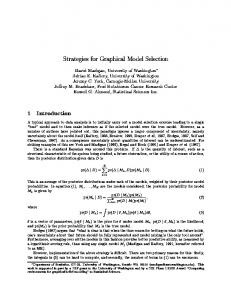
Another aspect is the conceptual model of the graphical model editor (cf. Fig. 4). It describes a view on the data model to visualise the data. To create a common understanding of the terms used in this section, we discuss a mock-up of a model editor (depicted in Fig. 3) along with the conceptual model (depicted in Fig. 4). A model is visualised in form of a Diagram having Vertices and Edges as children (cf. Fig. 3 and Fig. 4) (R1). A vertex corresponds to exactly one ObjectOccurrence of the data model and an edge represents exactly one RelationshipOccurrence. Each vertex has exactly one VertexTemplate that defines its appearance (R3), the available connection points (R6), and drop zones (R9). Hence, a vertex template represents a particular ObjectType, which
defines the type of an object occurrence. This also allows for describing all object types visually by means of vertex templates. The appearance of an edge is determined by the EdgeTemplate. As we described in Section 3, it is possible to define an edge between edges. Therefore, the edge template also defines all connection points (EdgeTemplateConnectionPoints) on edges (R6). Consequently, an edge template corresponds to a RelationshipType. Connection points of vertex and edge templates correspond to one ConnectionPoint of the data model. A drop zone of the vertex template represents only one DropZone. Therefore, all connection points and drop zones are linked to specific Roles. As mentioned above, an attribute representation is represented, for example, by a menu that can be opened via a right-click on the associated vertex object. The implicit edge is also not represented on the diagram, as it is used whenever the relationship of two objects is set up according to their mutual spatial position.
6
Implementation
In this section, we describe the implementation of the graphical model editor as generic and programming language-independent as possible. This simplifies any attempts to adapt or re-implement our graphical model editor. The visualisation technology to be used in the graphical model editor is the most important choice to make. It determines which features the graphical model editor will offer as well as the effort required to implement it. Using simple pictures has several drawbacks. First, pictures can only scale vertically and horizontally, which would not suite the requirements, for instance, of a UML class with many methods but a few attributes. Second, the quality of pictures is predefined and is worsening when the image is enlarged.
Enterprise Modelling and Information Systems Architectures Vol. 8, No. 2, December 2013 Developing Graphical Model Editors for Meta-Modelling Tools
57
Diagram
Template Preview Panel
Vertex
Vertex Templates
Edge
Figure 3: Mock-up of the graphical model editor
The alternative is using vector formats such as Scalable Vector Graphics (SVG), or GUI frameworks. In contrast to vector formats, modern GUI frameworks already incorporate the functionality for scaling and aligning their elements to show all viewable sub-elements. All of them have the features necessary to visualise model elements (e.g., drawing lines as well as rectangles or providing reusable layout containers). They differ with respect to their low level drawing technology. For example, Windows Presentation Foundation (WPF) is using vectors while Java Abstract Window Toolkit (AWT) is using pixel based operations. For reasons of performance, vector usage, declarative GUI definition and adaptation, as well as support for serialisability, we have chosen WPF for our implementation. WPF was designed to take advantage of modern graphics hardware and comes with support for DirectX. This accelerates the drawing of GUIs by utilizing the graphic hardware whenever possible. Definition of user interfaces and the program code implementing it are separated by WPF. The Extensible Application Markup Language (XAML) is used to describe the user interface in a declarative way. Consequently, model element representations can be defined using XAML. No procedural coding is necessary. All classes from Fig. 4 are implemented as WPF UserControls, with Diagram and TemplatePreviewPanel being exceptions to this rule. They
inherit from specific Panel classes. Thereby, the event handling and drawing mechanism of WPF are inherited. The Diagram is used as a root container for all model elements (cf. Fig. 4) (R1). As all model elements have a 2D position on the model (R2), we inherited from a WPF Canvas and extended it. We implemented a visual grid over the canvas along with snap-to-grid functionality for easier alignment. For zooming and scrolling we further extended the Canvas (R12). To allow for graphical export and printing, we could reuse the corresponding WPF features and implemented them in the Diagram class (R12). The VertexTemplate is used to describe all representational aspects of a vertex. Along with the actual graphical Symbol, which is drawn on the diagram, it defines available connection points, drop zones, and font properties (cf. Fig. 4). In XAML, the symbol is described in form of a string and is deserialised into a WPF object when it is drawn by a GUI element. This allows using any feature offered by WPF. One exemplary feature is the binding feature, which allows for self-refreshing visual properties that are linked to the attribute of an object. To represent all available object types of a modelling language, the corresponding vertex templates are displayed by their symbol in the TemplatePreviewPanel (cf. Fig. 3 and Fig. 4). The template
Enterprise Modelling and Information Systems Architectures Vol. 8, No. 2, December 2013 Hanns-Alexander Dietrich, Dominic Breuker, Matthias Steinhorst, Patrick Delfmann, Jörg Becker
58
Graphical Model Editor Diagram ...
0..*
Diagram
IEdgeRouter
Text
Children
Edge
Route() PreviewRoute() Router
Template PreviewPanel
IDiagramElement 1..1
Vertex
Path Z
X, Y, Z Width, Height
1..1 EdgeTemplate
EdgeTemplate ConnectionPoint X 0..* ConnectionPoints
1..1 VertexTemplate
EdgeTemplate
1..1
VertexTemplate Items
StartConnectionPoint EndConnectionPoint StartSymbol EndSymbol Colour Thickness Pattern
ITemplate Caption FontSize FontFamily
Symbol
0..* VertexTemplate DropZone
0..*
0..* ConnectionPoints
DropZones
VertexTemplate ConnectionPoint X, Y
Figure 4: Excerpt of the graphical model editor UML class diagram
preview panel inherits from a HeaderedItemsControl and allows creating vertices by dragging vertex templates onto the diagram. After dropping, a new Vertex will be created by the diagram, which uses the vertex template as a master. The new vertex deserialises the symbol from the template and uses it as its own representation. Therefor, the vertex was implemented by three layers (cf. Fig. 5 a). The deepest layer is used for the actual symbol, which is defined by the vertex template attribute symbol. The declarative XAML code can now access the attributes of the vertex or the object occurrence’s attributes over the binding feature and can adapt its visualisation
to them. On top of the symbol layer, we added the text layer. On the highest layer we implemented the connection point layer. We did so, because otherwise the text or symbol layer would hide the connection points. The actual position of the vertex is saved as X, Y, and Z coordinates. Z defines how the elements are stacked on top of each other. The connection point positions on the layer are defined by percentage values. X = 0 and Y = 0 defines the upper left edge, whereas X = 1 and Y = 1 defines the lower right edge. Using percentage values allows using the connection
Enterprise Modelling and Information Systems Architectures Vol. 8, No. 2, December 2013 Developing Graphical Model Editors for Meta-Modelling Tools
a) Vertex
59
b) Edge
Line layer End symbol layer
Symbol layer
Connection point layer
Te x
Connection point layer
Te xt
t
Start symbol layer Text layer Text layer
Figure 5: Exploded view of the Vertex and Edge UserControl
point layer independently from the actual Width and Height of the vertex. The drop zone implementation inherits from an ItemsControl. Thus, it is a class which can be integrated into the declarative XAML description. This allows for integrating a drop zone in the symbol. Furthermore, it is automatically arranged by the layout components that are integrated in WPF. When, for instance, a swimlane is changed in height or width, the corresponding drop zone is automatically altered to the same width or height. To use a drop zone, model elements can be dragged onto the drop zone area. If a valid relationship type is defined, the model element will be added to the drop zone. The drop zone itself has its own panel to arrange its children. By doing so, the layout container of WPF, like a Canvas or a StackPanel, can be reused (R10). This allows automatically adapting to the size of the drop zone’s content or supporting manual size modifications. The EdgeTemplate defines the appearance of the five edge layers (cf. Fig. 5 b). The lowest line layer is used to draw a line along the Path of an edge, which consist of x and y coordinates (cf. Fig. 4). The edge template specifies Thickness, Colour and Pattern of a line. Patterns define regular gaps in the line. The start and end symbol layers are used to display the rotated Start- and EndSymbol
according to the actual line direction. These symbols are defined by the edge template. In contrast to the vertex, the connection points of the edge are defined by only one value X. It defines the position on the line by a percentage value, where X = 0 means at the very beginning and X = 1 means at the end. The font properties of the vertex or edge text are defined by the attributes FontSize and FontFamily of the templates, which are inherited from ITemplate. To distinguish between different templates the Caption attribute of ITemplate is used to store a description. The actual edge or vertex Text is inherited from IDiagramElement (R11). To create an edge, we used a system to detect the actual element the mouse points to and allowed to draw an edge only between two connection points. The corresponding relationship type of an edge is determined automatically if it is unique with respect to the connection points’ roles. Otherwise, a wizard asks the user to choose one. The connected Start- and EndConnectionPoint are stored in the edge to save the start and end point. Whether two connection points can be connected at all depends on whether a suitable relationship type has been specified. Therefore, an algorithm hides invalid destination connections points once a user started drawing an edge (i.e., specified the source connection point).
Enterprise Modelling and Information Systems Architectures Vol. 8, No. 2, December 2013 Hanns-Alexander Dietrich, Dominic Breuker, Matthias Steinhorst, Patrick Delfmann, Jörg Becker
60
The IEdgeRouter interface defines two functions. They are used while drawing an edge between two connection points (PreviewRoute) and to compute the edge’s route through the diagram (Route) (cf. Fig. 4) (R8). The actual routing algorithm implements this interface and allows, for example, an orthogonal routing of an edge. As each edge has its own EdgeRouter, different routing strategies can be applied to edges. Due to the complexity of layout algorithms for vertices or complete diagrams (e.g., from the area of graph drawing), these features are out of the scope of this paper.
to be defined representing the object types the language is supposed to offer (Step 1). These vector graphics represent the shapes the modeller can use to develop the conceptual models. To define vector graphics, external software has to be used. To accomplish this task, basically any software that supports exporting XAML-files can be used. Examples of appropriate tools are Microsoft Expression Design or the open source software Inkscape. For more advanced vector graphics, that incorporate, for instance, a layout container, the GUI designer Microsoft Expression Blend can be used.
The integration of graphical model editor and representational aspects is done by serializing both the VertexTemplate as well as the EdgeTemplate and storing them in the corresponding representation. The edge and vertex templates were enriched to define not only their appearance with XAML, but also connection points, drop zones and the font properties.
In a second step, the vector graphics are then imported into the shape designer. The shape designer allows for creating a template file containing all imported vector graphics. Each of these vector graphics then has to be augmented by two attributes specifying (a) the connection points of the shape and (b) the way it can be labelled. The connection points represent the points an edge will be able to connect to. These points are specified using a grid structure that is superimposed on the vector graphic to help adjusting their position. To specify a label template for a vector graphic, the shape designer allows for selecting the font type as well as its size.
As all this information must be stored in a special format we implemented a so-called Shape Designer (R15). It allows a user-friendly editing of templates and stores them in a XML-file. This XML string is imported and stored in the representation. To manage attributes an editor can be opened using a menu. The creation of model elements, the change of position, etc. is signalled by events to the modelling environment, which creates or changes the corresponding objects in the data management layer. The events are consolidated in the Diagram class to provide a central access point for the meta-meta modelling environment. To draw an already created model, the API of the graphical model editor is used.
7
Defining Visual and Conceptual Aspects of a Modelling Language – an Example
The process of developing and using a conceptual modelling language is exemplarily depicted in Fig. 6. At first, a set of vector graphics has
To represent the relationship types of a modelling language, the shape designer allows defining edges (Step 3 in Fig. 6). An edge consists of three parts: a line style as well as an end- and startsymbol. The line style can simply be defined by specifying two parameters representing the length of the line and the length of a gap in the line. The latter parameter is optional and allows for specifying dotted and/or dashed lines. To represent the symbols of the edge, we need again vector graphics. With the shape of the edge defined, a connection point for the edge has to be specified next. With templates for nodes and edges defined, the template file containing all templates can be exported to a XML-file. This XML-file is then imported using the shape management (Step 4 in
Enterprise Modelling and Information Systems Architectures Vol. 8, No. 2, December 2013 Developing Graphical Model Editors for Meta-Modelling Tools
1
Create vector graphics (External program)
4
Import the created edge and vertex templates (Modelling tool)
2
Create vertex templates (Shape Designer)
5
Specify modelling language and assign templates (Modelling tool)
3
Create edge templates (Shape Designer)
6
Construct a model using the modelling language (Modelling tool: Graphical model editor)
Figure 6: Process of defining a modelling language’s visual and conceptual aspect
61
Enterprise Modelling and Information Systems Architectures Vol. 8, No. 2, December 2013 Hanns-Alexander Dietrich, Dominic Breuker, Matthias Steinhorst, Patrick Delfmann, Jörg Becker
62
Fig. 6). For each template a representation in the database is created that stores the corresponding serialised template. These representations can then be used to visualise the (directly visible) object and relationship types of the modelling language to be defined. The language editor is used to specify such a modelling language in two consecutive steps. First, all object and relationship types have to be defined conceptually with a wizard. The relationship types define which object types can be directly related to which other object types, thus comprising the syntactical rules of the modelling language. In a second step, object and relationship types need to be assigned to templates (or, in case of menu-based representation, to no template). To that end, the previously imported representations from the Shape Designer can be used. After the assignment, the imported connection points and drop zones are allocated to the roles they are representing (Step 5 in Fig. 6). In a last step, the modelling language can be used to develop conceptual models (Step 6 in Fig. 6). The tool offers the exemplarily implemented graphical model editor that contains a list of all available object types of the language in use. The object types are visualised by the templates that were assigned to them when the language was specified.
8
Contributions, Limitations and Outlook
In this paper, we presented requirements for graphical model editors in the context of distributed modelling, provided a conceptualisation of how such an editor could be designed, and finally presented an exemplary implementation of it, which is used as part of a meta-modelling tool. While there exists a considerable body of research on how meta-modelling tools ensure syntactical correctness of models created with DSMLs, this paper contributes to the actual visualisation of these DSMLs in a distributed modelling scenario. Therefore, we first examined existing tools with
respect to their representational capabilities. On top of these findings, we carved out a set of requirements for a graphical model editor as used within a distributed modelling scenario. Thereafter, we have shown a conceptualisation of these requirements by working out the interrelationship between the conceptual and the representational aspects of modelling languages and models. This conceptualisation was exemplary implemented and an application example was given. Compared to existing approaches discussed in Section 2, we provided the blueprint for a graphical model editor with a distinctive combination of features. It not only exhibits a high degree of representational flexibility, but also supports an easy-to-use development procedure not requiring users to know special programming languages. A further advantage of our graphical model editor is that representations (i.e., the shapes used to represent model elements) can be reused in multiple language specifications. Also, the process of creating these shapes is independent from the process of defining a modelling language. The language specification only uses the previously defined representations as part of the concrete syntax definition. Therefore, designers can work on the visual representations of language constructs while the domain experts are creating the language with its abstract syntax and semantics (Frank and Prasse 1997). The representations are described declaratively with XAML. Furthermore, all available GUI classes can be reused, for example, for layout purposes. This does not require any procedural coding and can therefore be accomplished by a higher number of users. With sophisticated tools such as Inkscape, Expression Design and Expression Blend, professional tool support for creating representations in XAML is readily available. As WPF and XAML run only on Windows systems and requires C#, not all design decisions are directly transferable to other systems or programming languages. But as frameworks like JavaFX for Java, QML for C++ and HTML5 share a lot
Enterprise Modelling and Information Systems Architectures Vol. 8, No. 2, December 2013 Developing Graphical Model Editors for Meta-Modelling Tools
of basic ideas with WPF, our approach can be used as a starting point to transfer our editor to another programming language. Naturally, we can never be sure that we have anticipated any conceivable requirement anyone will ever have for a graphical model editor. Any such requirements could require manual programming if it cannot be implemented with standard WPF features. As far as the reviewed modelling tools from Section 2 are concerned, we could not identify such a requirement. Regarding connection points of vertices, we encountered the problem that in some cases, connection points should not be arranged with respect to width and height of the vertices’ outer geometry. Therefore, the connection point layer should be integrated into the symbol and not overlay it. Then, the connection points can be arranged according to sub-elements of a vertex. The same holds true for the text layer, which sometimes should be arranged by a sub-element of a representation. In the current implementation, connection points are defined by percentage values and cannot be attached to special geometries like a bend of a line. We plan to add a corresponding functionality in the future.
References Aguilar-Savén R. S. (2004) Business process modelling: Review and framework. In: International Journal of Production Economics 90 (2), pp. 129–149 Bardohl R. (2002) A visual environment for visual languages. In: Science of Computer Programming 44 (2), pp. 181–203 Bardohl R., Ehrig H. (2000) Conceptual Model of the Graphical Editor GenGEd for the Visual Definition of Visual Languages. In: Proceedings of the Theory and Application to Graph Transformations
Bräuer S, Delfmann P, Dietrich H, Steinhorst M (2013) Using a Generic Model Query Approach to Allow for Process Model Compliance Checking - An Algorithmic Perspective. In: Proceedings of the 11th International Conference on Wirtschaftsinformatik (WI) (2013). Leipzig, Germany, pp. 1245–1259 Chen P. (1976) The Entity-Relationship Model – Toward a Unified View of Data. In: ACM Transactions on Database Systems 1 (1), pp. 9– 36 Clark H. H. (1996) Using language. Cambridge University Press, Cambridge Cook S., Jones G., Kent S., Wills A. C. (2007) Domain Specific Development with Visual Studio DSL Tools. Addison-Wesley Professional Costagliola G., Delucia A., Orefice S., Polese G. (2002) A Classification Framework to Support the Design of Visual Languages. In: Journal of Visual Languages & Computing 13 (6), pp. 573– 600 Davis R. (2008) ARIS Design Platform: Advanced Process Modelling and Administration. Springer, London Delfmann P, Herwig S, Lis Ł, Stein A, Tent K, Becker J (2010) Pattern Specification and Matching in Conceptual Models. A Generic Approach Based on Set Operations. In: Enterprise Modelling and Information Systems Architectures 5, pp. 24–43 Delfmann P., Herwig S., Karow M., Lis Ł. (2008) Ein konfiguratives Metamodellierungswerkzeug. In: Proceedings of the Modellierung betrieblicher Informationssysteme (MobIS) van Deursen A., Klint P., Visser J. (2000) Domainspecific languages: an annotated bibliography. In: ACM SIGPLAN Notices 35(6), pp. 26–36 Dietrich H, Steinhorst M, Becker J, Delfmann P (2011) Fast Pattern Matching in Conceptual Models - Evaluating and Extending a Generic Approach. In: Proceedings of the Enterprise Modelling and Information Systems Architectures (EMISA) (2011). Hamburg, Germany, pp. 79–92 Domokos P., Varró D. (2002) An Open Visualization Framework for Metamodel-Based
63
64
Enterprise Modelling and Information Systems Architectures Vol. 8, No. 2, December 2013 Hanns-Alexander Dietrich, Dominic Breuker, Matthias Steinhorst, Patrick Delfmann, Jörg Becker
Modeling Languages. In: Electronic Notes in Theoretical Computer Science 72 (2), pp. 69–78 Eclipse Graphical Modeling Framework (GMF) http://www.eclipse.org/gmf/ Last Access: 01/05/2012 Engstrom E., Krueger J. (2000) Building and Rapidly Evolving Domain-Specific Tools with DOME. In: Proceedings of the IEEE International Symposium on Computer-Aided Control System Design Erickson J., Siau K. (2007) Theoretical and Practical Complexity of Modeling Methods. In: Communications of the ACM 50 (8), pp. 46–51 Ermel C., Ehrig K., Taentzer G., Weiss E. (2006) Object Oriented and Rule-based Design of Visual Languages using Tiger. In: Proceedings of 3rd International Workshop on Graph Based Tools Esser R., Janneck J. W. (2001) Moses-a tool suite for visual modeling of discrete-event systems. In: Proceedings of the IEEE Symposia on Human-Centric Computing Languages and Environments Fowler M. (2002) Patterns of enterprise application architecture. Addison-Wesley Longman, Amsterdam Frank U. (2002) Multi-Perspective Enterprise Modeling (MEMO)-Conceptual Framework and Modeling Languages. In: Proceedings of the Hawaii International Conference on System Science Frank U. (2011) Some Guidelines for the Conception of Domain-Specific Modelling Languages. In: Proceedings of the 4th International Workshop on Enterprise Modelling and Information Systems Architectures Frank U., Prasse M. (1997) Ein Bezugsrahmen zur Beurteilung objektorientierter Modellierungssprachen – Veranschaulicht am Beispiel von OML und UML. In: Working Papers of the Institute of Information Systems of the University of Koblenz-Landau Giaglis G. M. (2001) A Taxonomy of Business Process Modeling and Information Systems Modeling Techniques. In: International Journal of Flexible Manufacturing Systems 13 (2),
pp. 209–228 Group O. M. (Jan. 2012a) OMG Object Constraint Language (OCL) Version 2.3.1 http://www. omg.org/spec/OCL/2.3.1/PDF Last Access: 04/02/2013 Group O. M. (Apr. 2012b) Unified Modeling Language Infrastructure Version 2.4.1 http:// www.omg.org/spec/UML/ISO/19505-1/PDF Last Access: 05/05/2012 Group T. O. (2009) ArchiMate 1.0 Specification. Van Haren Publishing, Zaltbommel Grundy J., Hosking J., Zhu N., Liu N. (2006) Generating Domain-Specific Visual Language Editors from High-level Tool Specifications. In: Proceedings of the International Conference on Automated Software Engineering Grundy J., Hosking J., Huh J., Na-Liu Li K. (2008) Marama: an eclipse meta-toolset for generating multi-view environments. In: Proceedings of the 30th International Conference on Software Engineering Grundy J. C., Mugridge W. B., G. H. J. (1998) Visual Specification of Multi-View Visual Environments. In: Proceedings of the IEEE Symposium on Visual Languages Haarslev V., Wessel M. (1996) GenEd – An Editor with Generic Semantics for Formal Reasoning about Visual Notations. In: Proceedings of the 12th IEEE Symposium on Visual Languages Himsolt M. (1995) Comparing and Evaluating Layout Algorithms within GraphEd. In: Journal of Visual Languages & Computing 6 (3), pp. 255–273 Junginger S., Kühn H., Strobl R., Karagiannis D. (2000) Ein Geschäftsprozess-management-Werkzeug der nächsten Generation. In: Wirtschaftsinformatik 42 (5), pp. 392–401 Kern H., Hummel A., Kuehne S. (2011) Towards a Comparative Analysis of Meta-Metamodels. In: Proceedings of the 11th Workshop on Domain-Specific Modeling Kolovos D., Rose L., Paige R., Polack F. (2009) Raising the Level of Abstraction in the Development of GMF-based Graphical Model Editors. In: Proceedings of ICSE Workshop on Modeling in Software Engineering
Enterprise Modelling and Information Systems Architectures Vol. 8, No. 2, December 2013 Developing Graphical Model Editors for Meta-Modelling Tools
Kosar T., Mernik M., Carver J. C. (2012) Program comprehension of domain-specific and general-purpose languages: comparison using a family of experiments. In: Empirical Software Engineering 17 (3), pp. 276–304 Kuhrmann M. (2011) User Assistance during Domain-specific Language Design. In: Proceedings of the ICSE 2011 Workshop on Flexible Modeling Tools (Flexi Tools) de Lara J., Vangheluwe H. (2002) AToM3: A Tool for Multi-formalism and Meta-modeling. In: Proceedings of the Fundamental Approaches to Software Engineering de Lara J., Vangheluwe H. (2004) Defining visual notations and their manipulation through meta-modelling and graph transformation. In: Journal of Visual Languages and Computing 15 (4), pp. 309–330 Larman C. (2004) Applying UML and Patterns: An Introduction to Object-Oriented Analysis and Design and Iterative Development. Prentice Hall PTR, New York Ledeczi A., Maroti M., Bakay A., Karsai G., Garrett J., Thomason C., Nordstrom G., Sprinkle J., Volgyesi P. (2001) The generic modeling environment. In: Proceedings of the Workshop on Intelligent Signal Processing Mendling J., Recker J., Reijers H. A. (2010) On the Usage of Labels and Icons in Business Process Modeling. In: International Journal of Information System Modeling and Design 1 (2), pp. 40–58 Mészáros T., Mezei G., Levendovszky T. (2008) A flexible, declarative presentation framework for domain-specific modeling. In: Proceedings of the Working Conference on Advanced Visual Interfaces Mili H., Tremblay G., Jaoude G. B., Lefebvre É., Elabed L., El Boussaidi G. (2010) Business process modeling languages: Sorting through the alphabet soup. In: ACM Computing Surveys 43 (1), 4:1–4:56 Minas M. (2002) Concepts and realization of a diagram editor generator based on hypergraph transformation. In: Science of Computer Programming 44 (2), pp. 157–180
Minas M. (2006) Generating Meta-Model-Based Freehand Editors. In: Proceedings of the Third International Workshop on Graph Based Tools zur Muehlen M., Recker J., Indulska M. (2007) Sometimes Less is More: Are Process Modeling Languages Overly Complex? In: Proceedings of the 11th International IEEE EDOC Conference Workshop Sapia C., Blaschka M., Höfling G. (2000) Using a Standard Repository Management System to Build a Generic Graphical Modeling Tool. In: Proceedings of the 33rd Hawaii International Conference on System Sciences Scheer A.-W. (2000) ARIS – Business Process Modeling. Springer, Berlin Schmidt D. C. (2006) Model-Driven Engineering. In: IEEE Computer 39 (2), pp. 25–31 Shen H., Wall B., Zaremba M., Chen Y., Browne J. (2004) Integration of business modelling methods for enterprise information system analysis and user requirements gathering. In: Computers in Industry 54, pp. 307–323 Teorey T. J. (1999) Database Modeling & Design. Morgan Kaufmann Publishers, San Francisco Tolvanen J.-P., Rossi M. (2003) MetaEdit+: defining and using domain-specific modeling languages and code generators. In: Proceedings of the Companion of the 18th annual ACM SIGPLAN Conference on Object-oriented Programming, Systems, Languages, and Applications White J., Schmidt D. C., Mulligan S. (2007) The Generic Eclipse Modeling System. In: Proceedings of the Model-Driven Development Tool Implementer’s Forum at TOOLS White S. A. (June 2004) Introduction to BPMN. IBM Cooperation http://www.zurich.ibm. com/~olz/teaching/ETH2011/White-BPMNIntro.pdf Last Access: 01/05/2012 Zachman J. A. (1987) A framework for information systems architecture. In: IBM Systems Journal 26 (3), pp. 276–292 Zhang K., Zhang D.-Q., Cao J. (2001) Design, Construction, and Application of a Generic Visual Language. In: IEEE Transactions on Software Engineering 27 (4), pp. 289–307
65
66
Enterprise Modelling and Information Systems Architectures Vol. 8, No. 2, December 2013 Hanns-Alexander Dietrich, Dominic Breuker, Matthias Steinhorst, Patrick Delfmann, Jörg Becker
Zhu N., Grundy J., Hosking J., Liu N., Cao S., Mehra A. (2007) A meta-tool for exploratory domain-specific visual language tool development. In: Journal of Systems and Software 80, pp. 1390–1407 Hanns-Alexander Dietrich University of Muenster – ERCIS, Leonardo-Campus 3, 48149 Muenster, Germany
[email protected] Dominic Breuker University of Muenster – ERCIS, Leonardo-Campus 3, 48149 Muenster, Germany
[email protected] Matthias Steinhorst University of Muenster – ERCIS, Leonardo-Campus 3, 48149 Muenster, Germany
[email protected] Patrick Delfmann University of Muenster – ERCIS, Leonardo-Campus 3, 48149 Muenster, Germany
[email protected] Jörg Becker University of Muenster – ERCIS, Leonardo-Campus 3, 48149 Muenster, Germany
[email protected]
Enterprise Modelling and Information Systems Architectures Vol. 8, No. 2, December 2013 Developing Graphical Model Editors for Meta-Modelling Tools
Appendix Capability C1: Specification at run-time
Rating –
C2: Multiple languages
X
C3: Editor for representations C4: Customizability of symbols
– B
C5: Customizability of edges
B
C6: Customizability of edge symbols
B
C7: Implicit relationships C8: Shared repository
– X
Comment The modelling environment requires recompilation of the model editor if changes are being made to the modelling language. The graphical user interface can display models of all modelling languages. No editor are provided. Predefined attributes of symbol representations can be edited. Predefined attributes of edge representations can be edited. Predefined attributes of edge symbol representations can be edited. Implicit relationships cannot be defined. Models and languages are stored in a shared repository.
Table 2: Capabilities of ADONIS
Capability C1: Specification at run-time
Rating (X)
C2: Multiple languages
X
C3: Editor for representations C4: Customizability of symbols
X B
C5: Customizability of edges C6: Customizability of edge symbols C7: Implicit relationships
B B –
C8: Shared repository
X
Comment The modelling environment can add new modelling languages at run-time. Specifying a new modelling language from scratch is not possible for ordinary ARIS users. They either have to be implemented by procedural programming or can be imported. The modelling environment is capable of presenting model editors for different languages. An editor is provided. A predefined set of shapes (rectangle, ellipse, polygon, etc.) is provided. A predefined set of properties is provided. A predefined set of properties is provided. Properties can be displayed and visually designed inside the representation, but not other language elements. Languages and models are stored in a shared repository.
Table 3: Capabilities of ARIS
67
68
Enterprise Modelling and Information Systems Architectures Vol. 8, No. 2, December 2013 Hanns-Alexander Dietrich, Dominic Breuker, Matthias Steinhorst, Patrick Delfmann, Jörg Becker
Capability C1: Specification at run-time
Rating –
C2: Multiple languages
X
C3: Editor for representations C4: Customizability of symbols
– B
C5: Customizability of edges
B
C6: Customizability of edge symbols C7: Implicit relationships
B –
C8: Shared repository
X
Comment The modelling environment requires recompilation of the modelling language definition if changes are being made to the modelling language and a restart if representations are changed. The modelling environment is capable of presenting model editors for different languages. No editor is provided. Predefined visual primitives called ‘icons’ are available. Predefined visual primitives called ‘arrows’ are available. Predefined visual primitives are available. Properties can be displayed and visually designed inside the representation, but not other language elements. Languages and models are stored in a shared repository.
Table 4: Capabilities of AToM3
Capability C1: Specification at run-time
Rating –
C2: Multiple languages
–
C3: Editor for representations C4: Customizability of symbols
– A
C5: Customizability of edges
A
C6: Customizability of edge symbols
A
C7: Implicit relationships
–
C8: Shared repository
–
Comment The modelling environment requires recompilation of the modelling language definition if changes are being made to the modelling language and a restart if representations are changed. The modelling environment represents each language in a separate ‘diagram editor’. No editor is provided. The language designer can include representations for symbols. The language designer can include representations for edges. The language designer can include representations for edge symbols. Properties can be displayed and visually designed inside the representation, but not other language elements. Languages and models are not stored in a shared repository.
Table 5: Capabilities of DIAGEN
Enterprise Modelling and Information Systems Architectures Vol. 8, No. 2, December 2013 Developing Graphical Model Editors for Meta-Modelling Tools
Capability C1: Specification at run-time
Rating –
C2: Multiple languages
–
C3: Editor for representations C4: Customizability of symbols
– A
C5: Customizability of edges
A
C6: Customizability of edge symbols
A
C7: Implicit relationships
–
C8: Shared repository
–
Comment The modelling environment requires recompilation of the modelling language definition if changes are being made to the modelling language and a restart if representations are changed. The modelling environment represents each language in a separate ‘diagram editor’. No editor is provided. The language designer can include representations for symbols. The language designer can include representations for edges. The language designer can include representations for edge symbols. Properties can be displayed and visually designed inside the representation, but not other language elements. Languages and models are not stored in a shared repository.
Table 6: Capabilities of DIAMETA
Capability C1: Specification at run-time
Rating –
C2: Multiple languages
–
C3: C4: C5: C6: C7:
– B B B –
Editor for representations Customizability of symbols Customizability of edges Customizability of edge symbols Implicit relationships
C8: Shared repository
–
Comment The modelling environment requires recompilation of the modelling language definition if changes are being made to the modelling language and a restart if representations are changed. The modelling environment represents each language in a separate ‘diagram editor’. No editor is provided. A shape library is available. A shape library is available. A shape library is available. Properties can be displayed and visually designed inside the representation, but not other language elements. Languages and models are not stored in a shared repository.
Table 7: Capabilities of DOME
69
Enterprise Modelling and Information Systems Architectures Vol. 8, No. 2, December 2013 Hanns-Alexander Dietrich, Dominic Breuker, Matthias Steinhorst, Patrick Delfmann, Jörg Becker
70
Capability C1: Specification at run-time
Rating –
C2: Multiple languages
–
C3: C4: C5: C6:
– A A A
Editor for representations Customizability of symbols Customizability of edges Customizability of edge symbols
C7: Implicit relationships
X
C8: Shared repository
–
Comment The modelling environment requires recompilation of the model editor if changes are being made to the modelling language. Each generated model editor belongs to a single language. No editor is provided. Programming symbols provides utmost flexibility. Programming edges provides utmost flexibility. Programming symbols of edges provides utmost flexibility. Relationships need not be visualised, but can also be connected via containment reference. Models are stored locally on a machine or possibly on a shared hard drive. There is no dedicated repository.
Table 8: Capabilities of EuGENia
Capability C1: Specification at run-time
C2: Multiple languages
Rating –
–
C3: Editor for representations
(X)
C4: Customizability of symbols
C
C5: Customizability of edges
B
C6: Customizability of edge symbols
B
C7: Implicit relationships
–
C8: Shared repository
–
Comment The modelling environment requires recompilation of the model editor if changes are being made to the modelling language. Each generated model editor belongs to a single language. As icons (pictures) are used, they can be designed with a 3rd party graphic tool. CSS style provides predefined properties like font, colour, background, etc. to change the labels or background of the icons. CSS line styles provide predefined properties like colour, thickness, line gap, etc. CSS line styles provide predefined start and end symbols of the edge. As GEMS was designed to support rapid prototyping of modelling languages with the use of icons (pictures), implicit relationships are not supported. Models are stored locally on a machine or possibly on a shared hard drive. There is no dedicated repository.
Table 9: Capabilities of GEMS
Enterprise Modelling and Information Systems Architectures Vol. 8, No. 2, December 2013 Developing Graphical Model Editors for Meta-Modelling Tools
Capability C1: Specification at run-time
Rating –
C2: Multiple languages
X
C3: C4: C5: C6: C7:
– B B B X
Editor for representations Customizability of symbols Customizability of edges Customizability of edge symbols Implicit relationships
C8: Shared repository
X
Comment GenEd uses description logic as a meta-meta-language. The resulting formulas represent the meta-model of a given language and need to be compiled to be usable as a modelling language. Multiple languages can be displayed in the model editor. No editor for arbitrary representations is available. Visual primitives are available. Visual primitives are available. Visual primitives are available. GenEd recognizes seven primitive spatial relations between object nodes (e.g., disjoint, touches, intersects, etc.) Models and languages are stored in a shared repository.
Table 10: Capabilities of GenEd
Capability C1: Specification at run-time
Rating –
C2: Multiple languages
X
C3: Editor for representations
X
C4: Customizability of symbols
B
C5: Customizability of edges
B
C6: Customizability of edge symbols
B
C7: Implicit relationships C8: Shared repository
– X
Comment A grammar editor is provided that allows for creating a visual language specification which is then translated to the usable modelling language. One graphical editor is provided that can display models created in the previously defined languages. A symbol editor allows for drawing arbitrary representations. Predefined attributes of symbol representations can be edited. Predefined attributes of edge representations can be edited. Predefined attributes of edge symbol representations can be edited. Implicit relationships cannot be defined. Models and languages are stored in a shared repository.
Table 11: Capabilities of GenGed
71
Enterprise Modelling and Information Systems Architectures Vol. 8, No. 2, December 2013 Hanns-Alexander Dietrich, Dominic Breuker, Matthias Steinhorst, Patrick Delfmann, Jörg Becker
72
Capability C1: Specification at run-time
Rating X
C2: Multiple languages
X
C3: Editor for representations C4: Customizability of symbols
– A
C5: Customizability of edges
A
C6: Customizability of edge symbols
A
C7: Implicit relationships
–
C8: Shared repository
–
Comment The modelling environment can reload the models at run-time if changes are being made to the modelling language. The modelling environment is capable of presenting model editors for different languages. No editor is provided. Decorators for programming symbols provides utmost flexibility. Decorators for programming edge symbols provides utmost flexibility. Decorators for programming edges provides utmost flexibility. Implicit relationships are supported by the abstract syntax but not by the model editor. GME supports multi user functionalities through subversion, but not the distribution of modelling languages.
Table 12: Capabilities of GME
Capability C1: Specification at run-time
Rating –
C2: Multiple languages
–
C3: C4: C5: C6:
– A A A
Editor for representations Customizability of symbols Customizability of edges Customizability of edge symbols
C7: Implicit relationships
X
C8: Shared repository
–
Comment The modelling environment requires recompilation of the model editor if changes are being made to the modelling language. Each generated model editor belongs to a single language. No editor is provided. Programming symbols provides utmost flexibility. Programming edges provides utmost flexibility. Programming symbols of edges provides utmost flexibility. Relationships need not be visualised, but can also be connected via containment reference. (The implicit relationship in the corresponding EMF model is defined as the attribute containment in the EReference class.) Models are stored locally on a machine or possibly on a shared hard drive. There is no dedicated repository.
Table 13: Capabilities of GMF
Enterprise Modelling and Information Systems Architectures Vol. 8, No. 2, December 2013 Developing Graphical Model Editors for Meta-Modelling Tools
Capability C1: Specification at run-time
Rating X
C2: Multiple languages
X
C3: Editor for representations C4: Customizability of symbols
– A
C5: Customizability of edges
A
C6: Customizability of edge symbols
A
C7: Implicit relationships
–
C8: Shared repository
X
Comment The graph grammar parser checks syntactical integrity constraints defined in the meta-model at run-time. The graphical user interface can display models of all modelling languages. No editor is provided. The language designer can include representations for symbols. The language designer can include representations for edges. The language designer can include representations for edge symbols. Properties can be displayed and visually designed inside the representation, but not other language elements. Models and languages are stored in a shared repository.
Table 14: Capabilities of GraMMI
Capability C1: Specification at run-time
Rating –
C2: Multiple languages
–
C3: C4: C5: C6: C7:
– B B B –
Editor for representations Customizability of symbols Customizability of edges Customizability of edge symbols Implicit relationships
C8: Shared repository
–
Comment The modelling environment requires recompilation of the model editor if changes are being made to the modelling language. Each generated model editor belongs to a single language. No editor is provided. A predefined set of shapes (e.g., rectangle) is provided. A predefined set of properties is provided. A predefined set of properties is provided. Properties can be displayed and visually designed inside the representation, but not other language elements. Models are stored locally on a machine or possibly on a shared hard drive. There is no dedicated repository.
Table 15: Capabilities of JComposer
73
Enterprise Modelling and Information Systems Architectures Vol. 8, No. 2, December 2013 Hanns-Alexander Dietrich, Dominic Breuker, Matthias Steinhorst, Patrick Delfmann, Jörg Becker
74
Capability C1: Specification at run-time
Rating X
C2: Multiple languages
X
C3: C4: C5: C6: C7:
X B B B X
Editor for representations Customizability of symbols Customizability of edges Customizability of edge symbols Implicit relationships
C8: Shared repository
–
Comment The modelling environment can generate the model editor at run-time if changes are being made to the modelling language. The modelling environment is capable of presenting model editors for different languages. No editor is provided. A predefined set of shapes (e.g., rectangle) is provided. A predefined set of properties is provided. A predefined set of properties is provided. Relationships need not be visualised, but can also be connected via containment reference. (The implicit relationship in the corresponding EMF model is defined as the attribute containment in the EReference class.) Models are stored locally on a machine or possibly on a shared hard drive. There is no dedicated repository.
Table 16: Capabilities of Marama
Capability C1: Specification at run-time
Rating X
C2: Multiple languages
X
C3: Editor for representations C4: Customizability of symbols
X B
C5: Customizability of edges C6: Customizability of edge symbols C7: Implicit relationships
B B –
C8: Shared repository
X
Comment The modelling environment can reload the models at run-time if changes are being made to the modelling language. The modelling environment is capable of presenting model editors for different languages. An editor is provided. A predefined set of shapes (rectangle, ellipse, polygon, etc.) is provided. A predefined set of properties is provided. A predefined set of properties is provided. Properties can be displayed and layouted inside the representation, but not other language elements. Languages and models are stored in a shared repository.
Table 17: Capabilities of Meta Edit+ Ver. 4
Enterprise Modelling and Information Systems Architectures Vol. 8, No. 2, December 2013 Developing Graphical Model Editors for Meta-Modelling Tools
Capability C1: Specification at run-time
Rating X
C2: Multiple languages
X
C3: C4: C5: C6:
– A A A
Editor for representations Customizability of symbols Customizability of edges Customizability of edge symbols
C7: Implicit relationships
–
C8: Shared repository
–
Comment The modelling environment provides interpreters for the modelling language definition to construct the modelling language at run-time. The modelling environment represents each language in a separate ‘graph editor’. No editor is provided. Programming symbols provides utmost flexibility. Programming edges provides utmost flexibility. Programming symbols of edges provides utmost flexibility. Properties can be displayed and visually designed inside the representation, but not other language elements. Languages and models are not stored in a shared repository.
Table 18: Capabilities of Moses
Capability C1: Specification at run-time
C2: Multiple languages C3: Editor for representations C4: Customizability of symbols
Rating –
– (X) A
C5: Customizability of edges
B
C6: Customizability of edge symbols
B
C7: Implicit relationships
X
C8: Shared repository
–
Comment The modelling environment requires recompilation of the model editor if changes are being made to the modelling language. Each generated model editor belongs to a single language. An assistant is provided. A GUI framework for programming symbols provides utmost flexibility. Predefined properties like straight or rectilinear routing (PDE is based on VS DSLT). Predefined properties like type of arrowhead (PDE is based on VS DSLT). Relationships need not be visualised, but can also be connected via Embedding Relationship (PDE is based on VS DSLT). Models are stored locally on a machine or possibly on a shared hard drive. There is no dedicated repository.
Table 19: Capabilities of PDE
75
Enterprise Modelling and Information Systems Architectures Vol. 8, No. 2, December 2013 Hanns-Alexander Dietrich, Dominic Breuker, Matthias Steinhorst, Patrick Delfmann, Jörg Becker
76
Capability C1: Specification at run-time
Rating X
C2: Multiple languages
X
C3: C4: C5: C6: C7:
X B B B –
Editor for representations Customizability of symbols Customizability of edges Customizability of edge symbols Implicit relationships
C8: Shared repository
–
Comment The modelling environment can generate the model editor at run-time if changes are being made to the modelling language. The modelling environment is capable of presenting model editors for different languages. An editor is provided. A predefined set of shapes (e.g., rectangle) is provided. A predefined set of properties is provided. A predefined set of properties is provided. Properties can be displayed and visually designed inside the representation, but not other language elements. Models are stored in an XML representation locally on a machine or possibly on a shared hard drive. There is no dedicated repository.
Table 20: Capabilities of Pounamu
Capability C1: Specification at run-time
Rating –
C2: Multiple languages
–
C3: Editor for representations C4: Customizability of symbols
X B
C5: Customizability of edges
B
C6: Customizability of edge symbols C7: Implicit relationships
B –
C8: Shared repository
–
Comment The modelling environment requires recompilation of the model editor if changes are being made to the modelling language. Each generated model editor belongs to a single language. An editor is provided. A predefined set of shapes (rectangle, ellipse, polygon, etc.) and anchors are provided. Predefined properties like colour, thickness, line gap, routing etc. Predefined properties like type of arrowhead. Properties can be displayed and layouted inside the representation, but not other language elements. TIGER aims at visual languages with a graphlike structure. Models are stored locally on a machine or possibly on a shared hard drive. There is no dedicated repository.
Table 21: Capabilities of TIGER
Enterprise Modelling and Information Systems Architectures Vol. 8, No. 2, December 2013 Developing Graphical Model Editors for Meta-Modelling Tools
Capability C1: Specification at run-time
Rating –
C2: Multiple languages
X
C3: C4: C5: C6:
– A A A
Editor for representations Customizability of symbols Customizability of edges Customizability of edge symbols
C7: Implicit relationships
–
C8: Shared repository
–
Comment The modelling environment requires recompilation of the model editor if changes are being made to the modelling language. The modelling environment is capable of presenting model editors for different languages. No editor is provided. Programming symbols provides utmost flexibility. Programming edges provides utmost flexibility. Programming symbols of edges provides utmost flexibility. Properties can be displayed and layouted inside the representation, but not other language elements. Models are stored locally on a machine or possibly on a shared hard drive. There is no dedicated repository.
Table 22: Capabilities of VisPro
Capability C1: Specification at run-time
Rating –
C2: Multiple languages
X
C3: Editor for representations
(X)
C4: Customizability of symbols
A
C5: Customizability of edges
A
C6: Customizability of edge symbols
A
C7: Implicit relationships
X
C8: Shared repository
–
Comment The modelling environment requires recompilation of the modelling language definition if changes are being made to the modelling language and a restart if representations are changed. The modelling environment is capable of presenting model editors for different languages. As XAML is used to describe the representations, they can be designed with a 3rd party XAML tool. A GUI framework for programming symbols provides utmost flexibility. A GUI framework for programming edges provides utmost flexibility. A GUI framework for programming edge symbols provides utmost flexibility. Relationships need not be visualised, but can also be connected via containment relationships. Models are stored locally on a machine or possibly on a shared hard drive. There is no dedicated repository.
Table 23: Capabilities of VMTS
77
78
Enterprise Modelling and Information Systems Architectures Vol. 8, No. 2, December 2013 Hanns-Alexander Dietrich, Dominic Breuker, Matthias Steinhorst, Patrick Delfmann, Jörg Becker
Capability C1: Specification at run-time
Rating –
C2: Multiple languages
–
C3: Editor for representations C4: Customizability of symbols C5: Customizability of edges
– A B
C6: Customizability of edge symbols C7: Implicit relationships
B X
C8: Shared repository
–
Comment The modelling environment requires recompilation of the model editor if changes are being made to the modelling language. Each generated model editor belongs to a single language. No editor is provided. Programming symbols provides utmost flexibility. Predefined properties like straight or rectilinear routing. Predefined properties like type of arrowhead. Relationships need not be visualised, but can also be connected via Embedding Relationship. Models are stored locally on a machine or possibly on a shared hard drive. There is no dedicated repository.
Table 24: Capabilities of VS DSLT