... implementation of an improved digital timer with audio-visual unit using .... digital clock, implemented with software codes which allow time to be set and reset, ...
International Conference on Information and Communication Technology and Its Applications (ICTA 2016) Federal University of Technology, Minna, Nigeria November 28 – 30, 2016
Development and Implementation of Microcontroller-based Improved Digital Timer and Alarm System
Lukman Adewale Ajao1, Mutiu Adesina Adegboye2, Eustace M. Dogo1, Salihu O. Aliyu3, and Danlami Maliki1 1
Department of Computer Engineering, Federal University of Technology, Minna, Niger State 2 Department of Electrical Engineering, Federal University, Oye-Ekiti 3 Department of Telecommunication Engineering, Federal University of Technology, Minna, Niger State clocks. All clocks measures time but different clocks have varying added functions or importance in their architecture. This experimental timer and alarm system design in this paper is aimed at time control in regular symposium, in order to solve the usual problems of time delay or overlaps during presentations by sugar coated mouth presenter or people with too many materials, since overtime is an offense to the audience, particularly if there are parallel sessions. Well, this device brings the solution, since it contains timer with light indicator unit (Green, Yellow and Red) and alarm system to tell the presenter the actual time spent logically. Mechanical and electromechanical clocks are being modified and replaced by microcontroller-based digital clocks, this is due to the reduced cost, higher reliability, less power consumption, portability, wide variety of changeable functions by reprogramming the chip and adding new product features. In addition to these, it gives confidence to the experts and student in the area of embedded systems by (learn-while doing) undertaking certain simple in-house experiments with frequent practice on microcontroller-based electronics circuit design and simulation and the replacement of analog devices or components to achieve better performance operation and simple circuit [2].
Abstract—Time plays an important role in our daily activities, more particularly in sectional events or conference arena where there is need for accurate time management. This paper focuses on the development and implementation of an improved digital timer with audio-visual unit using (PIC16F887) microcontroller chip and other electronics component such as LCD, 7-segment display, LED and buzzer as an I/O device. Thus, the need for this device in our daily activities is to monitor the time scheduled for events, updating and alert the audience using an audio-visual approach. The proposed system allows apt time management and avoids time wastage during seminar presentations and the likes. It particularly helps presenters to be time conscious, thus, making them to naturally adjust such that the allotted time is enough to cover up their presentation. The digital timer and alarm system presented herewith is also of advantage to the physically challenged like the deaf and blind in monitoring their sectional activities and to be fully involved about the event situation. The system was designed in different modules, and all were interfaced together with firmware chip to simplify the mechanism’s fault diagnoses and fault corrections. Keywords-digital timer, signal module, conference arena, physically challenged, firmware chip.
I.
INTRODUCTION
II.
Watches or other timing devices are very important in tracking our daily activities. Timing control and alert system is significant in every aspect of our lives beyond just to tell what time of the day it is. The science of time began when humans started analyzing the patterns of light and darkness which lead to development of the calendar year and a clock based on 60-seconds/minute, 60-minutes/hour and 24hours/day. Clock has been designed in different architecture with functions to determine or solve many problems like day and night period, to control periodic events, to ring a bell every hour or minute, to open doors, run machinery and play music. Presently, humans are controlling actions within the environment in a programmed and predictable manner [1]. Therefore, keeping of time is basic for all control systems. In every conferences chamber, public room, schools and other convention arena nowadays, timing is a very essential factor considered in the gathering for the coordination and managing of the event. Due to the level of technology nowadays, time is mostly measured electronically using
RELATED WORKS
Several significant papers have been reviewed on the microcontroller-based timing system, which led to this improved digital seminar timer and alarm system development and implementation. The design of a microcontroller-based intelligent digital volume with timer was put forward by the authors in [3]. Their system design is a computer based timer with speaker volume controller, it cannot be used in the conference arena for timing and alarm purposes because of its complexity and difficult to operate since it uses serial communication port and setup. The authors in [4], designed a digital clock using microcontrollerbased system with seven-segment display to display time base on the program coding. The system could not display year, month or day and no alarm system. Also, it became relatively expensive due to the use of external decoder. Another effort was made on microcontroller-based timing system in [5]. They came up with a 24 segment display for Bangla characters and numerals. Similarly, another effort was made by the authors in [6] towards 184
International Conference on Information and Communication Technology and Its Applications (ICTA 2016)
developing a 10-segment display for Bangla digits, but their segments were not uniform, also, it had some controversy in portraying digits such as “1”, “2”, “3”, and “7” accurately. Furthermore, the work in [7] improved on the work of [5] and [6] by coming up with design of an 11-segment display for Bangla, Arabic and English numerals. This design gives a uniform results and it complements the effort of the previous authors without any segment intersections. Microcontroller based digital Bangla clock and calendar, which display Bangla digits on the 16x2 LCD was put forward by [8]. The author used ATmega8 microcontroller and basic language for the system coding and programming. The clock functions in dual mode of performance, it display digits in both English and Bangla language. No alarm unit incorporating with the system for the message notifications. The electric heating timer based system using Atmel AT89S52 microcontroller was developed by [9]. The system deals with the designing of biomedical related equipment for pain relief based on time dependent heat therapy, which performs count-down operation from 0000 – 9999 minutes with four 7-segment display showing the actual time left for the heat therapy. The system is functioning well in the area of application but lack of monitoring and alarm system when the time elapsed. Author in [10] discuss an approach for managing alarms and diagnosis in an automation management system and integrated information technology milieu, using WBEM/CIM approach technologies. Since, the integration of system management of enterprises and industrial automation become increasingly connected. Therefore, it requires alarms and diagnosis governed system. The shortcoming of the system does not involved timing and logical method of managing industries like light indicator and others. In this paper, we intend to develop and implement a microcontroller based digital timer and alarm system to enable presenters strictly adhere with time specification and management in conference arena or events. The system consists of three major sections which will be discussed under system design and methodology. The device contains a digital clock, implemented with software codes which allow time to be set and reset, alarm system to alert user when the preset times elapse and indicating light which tell the time conditioning logically. III.
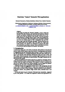
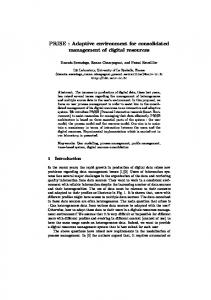
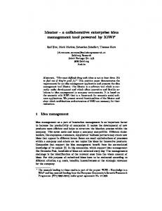
performances. The input unit, this unit used combination of (4x4 keypad) for the timing digits input to the system for the processing. Therefore, the output units are divided into three parts: First, the implementation of a 16x2 (LCD) module, which display timing digit pressed for the system operation and time received message display as shown in the figure 9. Secondly, the 7-segment display was programmed to respond to any input time digits for the count-down timer. Thirdly, the (LED) indicator and buzzer, this was designed and arranged serially using time delay to respond to changes in an input timing by shown green light when input timing is fresh, then changed the state when the count-down timer is left with 5 seconds to the end and activate yellow LED, and finally changed the state of LED to RED light when the input timing elapsed. At this stage, the buzzer will be activated immediately and raised alarm to show the accuracy of the system. With all features attached to this system and its performances make it an improved digital clock and alarm system over the existing one as reported in the literature review. This will assists presenters to strictly adhere with time specification and management in the conference arena or events. It will also help the physically challenged people to be fully involved about the present situation of the event and to manage their daily time activities. In achieving this system, it involves modular implementation of the different units separately before each of the module were linked together to function as a system unit. This give advantages of operating the system easily, and make the fault isolation and fault detection simple. The system was designed to be powered through 5V universal serial bus (USB) port; all components are connected to the common 5V line and grounded. The structural design of an improved digital seminar timer and alarm system is given in Fig. 1.
KEYPAD
MCU (PIC16F887)
LCD DISPLAY 7-SEGMENT DISPLAY
POWER SUPPLY UNIT
SYSTEM DESIGN AND METHODOLOGY
The Microcontroller based improved digital timer and alarm system was design and implemented with the use of both hardware and software approaches for the design, development and implementation in modular programming. In our design, the software used in the program coding was MikroC Pro for PIC using micro C language. The circuit development was simulated, programmed and demonstrated using Proteus Virtual System Modeling 8.0 (PVSM) and PICKit3 debugger was employed in the process for the real life scenario programming of the microchip. Therefore, the hardware implementation of the microcontroller based improved digital clock and alarm system was carried out and tested on the breadboard before finally soldering on the veroboard. The hardware design comprises of different module like the system controller unit where (PIC16F887) microcontroller was used for the system programming and
LED INDICATOR
ALARM (BUZZER)
Figure 1. Structural design of microcontroller-based digital timer and alarm system
A. System Controller Unit The PIC 16F887 Microcontroller was used as an intelligence device, which control and coordinate all the activities carried out by the system development. This chip belongs to a mid-range 8 bits architecture and 14 instructional word length of microchip, it consists of 40 pins (1-40) and 5 ports coded as Port (A-E). Port A to port D are 8 bits bidirectional digital input/output (I/O) ports with 185
International Conference on Information and Communication Technology and Its Applications (ICTA 2016)
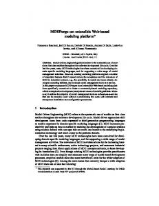
additional port bits as shown in the figure 3, while Port E is a 4-bit bidirectional input/output ports. Therefore, the other four pins like pin (11 and 12, 31 and 32) are for the controller power (Vss) and ground (GND) respectively, most of the pins of this chip are multifunctional pins and multipurpose. Details description of some selected pins number was given in the table 1. For instance, pin 1 (RE3/MCLR/VPP), pin 5 (RA3/AN3/VREF+/C1IN+), pin 13 (RA7/OSC1/CLKIN) and pin 39 (RB6/ICSPCLK ). PIC16F887 has high performance RISC CPU with features of high operating speed; it works on 4-20MHz oscillator/clock input and 200ns instruction cycle [11]. It also contains three timer modules; Timer0, Timer1 and Timer2, where timer0 module was used for the timing in this work. The OPTION register is a readable and writable register which contains various bits to configure the Timer0/WDT prescaler, External INT interrupt, Timer0 and Weak pull-ups resistor on PORTB.
to the microcontroller of the system. The four button pins along the column are configure to be inputs and grounded (GND), while all the four buttons across the rows are configure to be output as shown in the simulation circuit design in figure 9. The four input pins along the column are connected to the Port D (RD0-RD3) of the microcontroller and grounded, while the other output four pins across the row of the button are connected to the Port D (RD4-RD7) with 10k resistor for each connection pins. If one of the sixteen buttons is pressed, it connects a pair of pins together. This feature helps in detecting which button is pressed. The internal and external architecture of the keypad connection was shown in the figure 4 and figure 5 respectively.
A
B
TABLE I.
DETAILS OF SOME SELECTED PIN NUMBERS AND DESCRIPTION OF PIC16F887 MICROCONTROLLER CHIP.
Pin N0 1
Pin Name
Description
RE3/MCLR/VPP
RE3: Digital I/O Port E, Pin 3 MCLR: Low logic controller power reset or clear screen. VPP: Microcontroller programming voltage RA3: Digital I/O Port A, Pin 3 AN3: Analog to Digital channel 3 VREF+:Analog to Digital positive voltage reference input C1IN+: Positive input comparator 1 RA7: Digital I/O Port A, Pin 7 OSC1: First input crystal oscillator CLKIN: External clock input RB6:Digital I/O Port B, Pin 6 ICSPCLK: Serial clock programming
5
RA3/AN3/VREF+ /C1IN+
13
RA7/OSC1/CLKI N
39
RB6/ICSPCLK
C
D
1
2
3
4
Figure 3. Internal architecture of 4 x 4 matrix keypad connections
Figure 4. External architecture of 4 x 4 matrix keypad connection
C. Output Unit The first output device used in this system was 16x2 LCD (HD44780) parallel interface chipset, 16 pins connection, easy to configure and program which commonly used in the various simple and complex embedded systems to exhibit output information. LCD (Liquid Crystal Display) is an electronic module use to display alphanumeric data on the screen, a 16x2 LCD denotes 16 columns and 2 rows capable of displaying 16 characters per line/row and there are two (2) of such lines/rows. In this work, 4-bit data mode (D4-D7) was used instead of the 8-bit counterpart. The data line pin (D4-D7) of LCD was connected to the port C, pin (15-18) of microcontroller respectively. In the process of interfacing the LCD with microcontroller, the LCD pins was connected accordingly as shown in the figure 6a before embarking on the bread boarding and soldering.
Figure 2. Pin configuration of the PIC 16F887 microcontroller chip
B. The Input Unit (4x4 matrix keypad) In this work, 4x4 matrix keypad was used as a data input device for the system timing or logical configuration of the system operation. In the process of connection, the four button pins along the rows are connected with the four buttons pins across the column to reduce the input connection switches to 8 pins, which are directly connected 186
International Conference on Information and Communication Technology and Its Applications (ICTA 2016)
(a)
(b) Figure 5. Pin configuration and circuit implementation of 16 x 2 LCD module
D. Seven Segment Display Unit A seven segment display is the most common basic electronic display device capable to demonstrate digits from 0-9 and beyond in a clearly digital form. It can be used in many applications of electronics and embedded system devices to display numeric information like in the digital clocks, radio, microwave ovens, electronic meters etc. The arrangement are laid out as a squared-off shown in the in Figure 7, every LED is assigned a name from 'a' to 'h' and is identified by its name. Seven LEDs 'a' to 'g' are used to display the numerals while 'h' is used to display the dot/decimal [12]. Common cathode type of seven-segment display was used in this design, the pin 11 and 12 of the device was connected to the Port A, pin (2-5) of microcontroller using NPN 2n2222 transistor to improve the brightness of the display. Also, the pins connection of the each 2-digit seven segment display (a-g) and the decimal point (dp) was connected together and directly connected to the port B, pin (33-40) for the digit display. In CC configuration, the negative terminals of all LEDs are connected to the common pins (low voltage) and common pin is connected to ground to glow a particular LED when its corresponding pin is given high logic to display a number.
Figure 7. LED connection to microcontroller
From Figure 7, using voltage divider rule with Vcc where thus:
RD is the resistance of the green LED, R1 is obtained
VR1
Vcc R1 R1 RD
R1Vcc VR1 ( R1 RD ) R1 (Vcc VR1 ) VR1 RD R1 Figure 6. The cascaded four seven segment display and the pin configuration of each segment
9V ,
VR1 RD Vcc VR1
(1)
900 100 300 12 9
F. Audio Unit A buzzer is an audio signaling device, which may be mechanical, electro-mechanical, or piezoelectric. The wide areas of application of buzzers include: alarm devices like clock, timers and confirmation of user input such as a mouse click or keystroke [14]. The buzzer is connected with NPN transistor, wired with the third LED that indicating stop and connected to the port E, pin 10 of microcontroller. This device was configured and programmed to sounds whenever the preset time interval has elapsed or when red light is activated (STOP). Figure 8 depicts the wiring method of buzzer in our design.
E. Light Emitting Diode Unit The application of (LED) in this development system was divided into two functions. First, it serves as an indicator light, and also as control and monitoring timing system. Three different color of LED was used for the control and monitoring system (Green, Yellow and Red) which indicate time begins, ready to stop and stop respectively. The LED was connected to port E, pin (8-10) of microcontroller, the buzzer and then grounded [13]. 187
International Conference on Information and Communication Technology and Its Applications (ICTA 2016)
V.
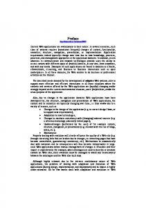
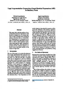
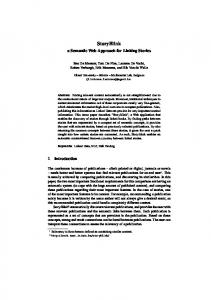
SYSTEM FLOWCHART
Start Input Time No
Is time valid?
Figure 8. Wiring method of buzzer with NPN transistor
Yes
From Figure 8, we have:
Count down on green LED
VB I B RB VBE 2 103 IB 10 A 200 VB 10V Ic
No
(2)
Has 90% of time elapsed?
VBE 0.7V Therefore,
RB which is the base resistor of the transistor is
Yes
obtained as:
RB
VB VBE 10 0.7 930 IB 10 106
Put ON Yellow LED and count down
(3)
No
Hence, a 1KΩ resistor value was used.
IV.
Time Up? Yes
DISCUSSION
The development and implementation of microcontrollerbased digital timer and alarm system was design and tested to ensure workability and reliability of its performance. The system can be programmed for timing purposes by connecting it to the laptop through a USB port for powerdriven, and simply press the ‘*’ key on the keypad to prepare the system for data input or timing code. Then press the ON/OFF key to enter the countdown time or event time. For the proper interaction, the digits pressed/entered are displayed on the LCD, when the user is done with timing range, the ‘#’ key is pressed and the system checks the time inputs. If it is a valid time, the message display on the LCD “TIME RECEIVED” or else display “INVALID TIME”. This required a user to enter a valid time. But if a valid time is entered, the time will be shown on the “7-Segment Display”, activating the green light and the time will start counting. When countdown time reaches 90% of the stipulated time, the Green LED goes off and activates yellow LED. Once the countdown time expired, the yellow LED goes off and activates Red LED as well as buzzer activated to sound in support of expiring time set.
Put ON Red LED, Sound Alarm Stop Figure 9. Flow chart of microcontroller based digital timer and alarm system
VI.
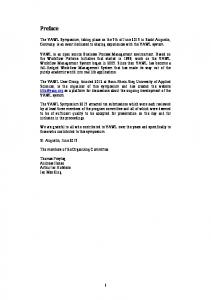
IMPLEMENTATION
The design is an embedded microcontroller-based system, with LCD, LED, seven segment display, keypad, buzzer and others electronic components. It is divided into hardware and software parts. In the software part, the MicroC program on the controller core can initialize the parameters, configure the simulation and communicate with the hardware model. If the time set for the system is 5 minutes in the clock, green light is activated and glow indicate the beginning of 188
International Conference on Information and Communication Technology and Its Applications (ICTA 2016)
time, and counter will count by decreasing timer till it gets to 1 minute to the end of timing, after which the yellow LED will come up to tell about the timing. Finally, when it counts to exactly 5 minutes of the total timing, the red lights will be
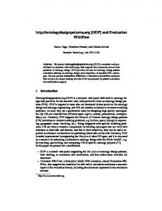
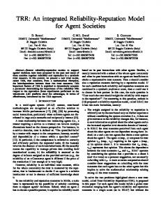
activate and turn ON, at the same time it triggers the alarm system; the buzzer immediately comes up and interrupts the presenter logically. Details implementation and testing of the digital timer and alarm system are shown in the figure 11. +5v
+5v
+5v +5v
RV1
+5v
LCD1
44%
LM016L
Q1
10k
2N2222
VSS VDD VEE
Q3
1 2 3
2N2222
D0 D1 D2 D3 D4 D5 D6 D7
2N2222
RS RW E
2N2222
7 8 9 10 11 12 13 14
Q2
4 5 6
Q4
R4 R5
2k
R2
R3
2k
2k
+5v
2k
R1
R9
20k
330
D1 LED-GREEN
U1 1 2 3 4 5 6 7 14 13 33 34 35 36 37 38 39 40
RE3/MCLR/VPP
RC0/T1OSO/T1CKI RC1/T1OSI/CCP2 RA0/AN0/ULPW U/C12IN0RC2/P1A/CCP1 RA1/AN1/C12IN1RC3/SCK/SCL RA2/AN2/VREF-/CVREF/C2IN+ RC4/SDI/SDA RA3/AN3/VREF+/C1IN+ RC5/SDO RA4/T0CKI/C1OUT RC6/TX/CK RA5/AN4/SS/C2OUT RC7/RX/DT RA6/OSC2/CLKOUT RA7/OSC1/CLKIN RD0 RD1 RB0/AN12/INT RD2 RB1/AN10/C12IN3RD3 RB2/AN8 RD4 RB3/AN9/PGM/C12IN2RD5/P1B RB4/AN11 RD6/P1C RB5/AN13/T1G RD7/P1D RB6/ICSPCLK RB7/ICSPDAT RE0/AN5 RE1/AN6 RE2/AN7
15 16 17 18 23 24 25 26 19 20 21 22 27 28 29 30 8 9 10
PIC16F887
330
9
5
6
C
1
2
3
ON
0
=
C 1
D
+ 4
R8
330
8
4
3
R7
330
7
B
2
R6
A
+5v
BUZ1
BUZZER
R10
R11
R12
R13
10k
10k
10k
10k
Q5 2N2222
Figure 10. Complete simulation circuit diagram of digital timer and alarm system
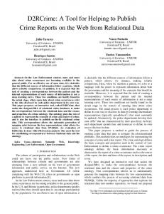
Figure 11. Implementation of digital timer and alarm system on the breadboard
Figure 13. Packaging of the digital timer and alarm system
VII. COMPARATIVE STUDY WITH SIMILAR WORK IN LITERATURE REVIEW
The development of microcontroller based improved digital timer and alarm system put forward in this paper was evaluate by comparing with the existing similar work in the literature from the perspective of the components used, performances and their area of applications.
Figure 12. Implementation of digital timer and alarm system on the Vero board
189
International Conference on Information and Communication Technology and Its Applications (ICTA 2016) TABLE II. S/N 1.
2.
3.
4.
COMPARATIVE STUDY WITH SIMILAR WORK IN THE REVIEW LITERATURE.
Author & Year Victor et al. (2012)
Diptarup and Sukalyan, (2012)
Mizanur et al. (2012)
Arushi & Sakshi (2016)
Project Title Design and development of microcontroller based digital bangle clock
Microcontroller based intelligent digital volume controller with timer
Microcontroller and LCD based digital Bangla Clock and calendar
Timer Electric Pad
based Heating
firmware technology like System-on-Chip (SoC), complex programmable logic device (CPLD) or field programmable gate array (FPGA), Arduino microcontroller etc to make the device efficient, portable compact, and more functions.
Parameter of Comparison The author employed ATmega 32 microcontroller and 7segment display in their design to show the digits in both English and Bangla languages, but no LCD and alarm system The system was designed to control music system and volume level using Atmel 8051 microcontroller, 7segment display and others. Based on their focus, alarm system, LCD is not considered. Atmel 8051 microcontroller, LCD, 7segment display was used in their design to display time and calendar in Banglar language. The system is not capable of alerting. The authors used Atmel 8051 microcontroller, 7segment display and heating element for their design as time totalizer for dependent heat therapy. No alarm system inclusive in the designed should in case of monitoring.
REFERENCES [1]
[2]
[3]
[4]
[5]
[6]
[7]
[8]
[9]
VIII. CONCLUSION [10]
This work presents the development and implementation of microcontroller-based improved digital timer and alarm system. It is applicable for monitoring time preset, avoid premature abortive time measures and enhance effective time usage by updating and alerting audience in the conference arena. The completed work was tested to ensure that the required task of timing, alerting and interrupting were all well done. This was established to improve on learning idea, enhanced research and technological improvement on embedded system design and development using microcontroller chip. The simulation, bread boarding, soldering and the final packaging of the device was also presented. Further research work may include using other
[11] [12]
V. K. Sarker, M. A. Rahman, and M. A. Matin “Design and Development of Microcontroller Based Digital Bangla Clock”, International Journal of Computer Theory and Engineering, Vol. 4, No. 6, December 2012. L. A. Ajao, J. Agajo, J. G. Kolo, M. A. Adegboye, Y. Yusuf, “Learning of Embedded System Design, Simulation and Implementation: A Technical Approach”, American Journal of Embedded Systems and Applications, Vol. 3, No. 3, pp. 35-42., May 2016. D. Paul and S. Som, “Microcontroller Based Intelligent Digital Volume Controller with Timer”, International Journal of Computer Applications, 38(1):19-26, January 2012. P. T. Tun, “Development and implementation of microcontroller-based digital clock,” World Academy of Science, Engineering and Technology Conference, Singapore. vol. 42, June 2008. M. S. Arefin, M. A. Dewan, M. I. Khan, and M. S. Islam, “Designing a 24 segment display for Bengali numerical digits and characters”, 3rd International Conference on Electrical and ComputerEngineering ICECE, pp. 549-552, 2004. S. Ahmed and S. Monira, “Designing a 10 segment display for Bangla and English numerals”, Proceedings of ICCIT, pp. 602 605, 2007. M. O. Rahman, M. A. Azim, M. S. Chowdhury, and M. N. Islam, “Defferent segment displays for Bangla, English and Arabic digits”, Proceeding of ICCIT, pp. 299-302, 2003. M. Rahman, A. Islam, R. S. Rajan, D. M. parvez, R. Islam, M. N. Islam, “Microcontroller and LCD based digital Bangla clock cum calendar”, International Journal of Engineering Research and Development, Volume 4, Issue 1 Pg.99-103, 2012. A.Vats, S. Sethi, “Timer Based Electric Heating Pad”, International Journal of Innovative Research in Science, Engineering and Technology, Vol. 5, Issue 5, May 2016. R. Lehmann, A. Dennert, M. Wollschlaeger, S. Trebing, “Diagnosis, Alarms and their Management in integrated Automation Systems”, IEEE, 2015. “Microchip PIC 16F887 datasheet”, retrieved from www.microchip technology.inc, Retrieved May, 2015. “7-Segment Display”, retrieve from http://www.engineersgarage.com/ electronic-components/7segment-display.
[13] A. Abubakar, T. Mantoro, S. Moedjiono, H. Chiroma, A. Waqas, “A Support Vector Machine Classification of Computational Capabilities of 3D Map on Mobile Device for Navigation Aid”, International Journal Of Interactive Mobile Technologies, 2016. [14] "Buzzer - definition of buzzer by The Free Dictionary".
Retrieved May 2015.
190