Available online at www.sciencedirect.com
Procedia CIRP 00 (2014) 000–000 www.elsevier.com/locate/procedia
6th CIRP International Conference on High Performance Cutting, HPC2014
Development of a chip pulling system for efficient turning Burak Sencera*, Tomoya Aokib, Eiji Shamotoa, Takumi Hasegawaa, Tomio Koidec a
Nagoya University, Graduate School of Engineering, Nagoya, 464-8623, Japan b Toyota Central R&D Labs. Inc., Nagakute, Aichi, Japan c Murata Machinery, Ltd., Inuyama, Aichi, Japan
* Corresponding author. Tel.: +81-52-789-4491; fax: +81-52-789-3107. E-mail address:
[email protected]
Abstract Combined with the chip guiding, this paper presents a new “assisted turning method” where the cut chip is pulled using an external pulling device to improve the performance of turning process. In the proposed method, straight unbroken chip is generated by utilizing special tool tips and guided through a guide tunnel for automated chip pulling. The first prototype of chip pulling device is designed that can pull the guided straight chip continuously as the turning operation is carried on. Design of the chip pulling system, proposed pulling device and its automatic control are presented in this research. A brief insight on the effect of chip pulling to the turning process is discussed by inspecting fundamental process parameters. Experimental results show that by pulling the chip in a controlled manner, process can be improved dramatically. Cutting forces and temperature are effectively reduced in actual “chip pulling turning”. © 2014 The Authors. Published by Elsevier B.V. Selection and peer-review under responsibility of the International Scientific Committee of the 6th CIRP International Conference on High Performance Cutting. Keywords: Turning; Process Control
1. Introduction Turning is an efficient machining process where high material removal rate can be obtained. The process is mainly controlled by a small set of parameters such as depth of cut, cutting feed and speed. Those cutting conditions are selected by the process planner where several factors such as toolworkpiece pair, cutting forces, vibrations and tool life [1] force a compromise to be made between high material removal rate and machining accuracy/stability. The challenge is to exceed the limits to improve efficiency and accuracy of conventional turning by introducing new principles. This paper presents a new turning system where, unlike conventional approaches, process is controlled externally by pulling the cut chip to attain high performance turning. The chip pulling force is introduced as a new parameter to control and improve the process. In practice, optimal cutting conditions are determined utilizing process models, through experience and finally by trial and error. In an attempt to deliver the highest productivity, cutting process may be tuned adaptively using
monitoring information from external or, in-machine sensors [2, 3]. However, these approaches base on adjusting the existing cutting conditions and provide only a limited amount of improvement within the known process limits.
Fig. 1. Chip-pulling turning process
Elliptical vibration cutting [4] was introduced as an enhancement to conventional turning process for low speed ultra-precision machining. The tool is vibrated elliptically in cutting and chip flow directions to control and reverse friction on the rake face, which in return reduces cutting forces,
2212-8271 © 2014 The Authors. Published by Elsevier B.V. Selection and peer-review under responsibility of the International Scientific Committee of the 6th CIRP International Conference on High Performance Cutting.
2
B.Sencer, et.al./ Procedia CIRP 00 (2014) 000–000
overall cutting energy and heat generation. In a similar way, it has been proposed that pulling the cut chip could reduce the friction and improve cutting process greatly [5]. Nevertheless, chip pulling cutting could not been realized so far due to lack of suitable chip control methods [6]. A chip guiding method has been proposed recently to generate straight continuous chip [7], which has given the opportunity to automatically pull the cut chip.
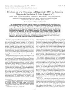
2. Development of the Pulling System 2.1. Electro-mechanical Design Once the cut chip is guided away from the cutting point, it is pulled by the designed chip-pulling device as shown in Fig. 2. The pulling device for controlled chip-pulling cutting consists of a pair of rollers driven by servo motor system. The front view of the pulling device is show in Fig. 2(b) and the top view is given in Fig. 2(c). Servo torque is controlled by a control system and transferred to the rollers via a gearbox with a total gear ratio of ½. Rollers are made of hardened steel and their width is 10[mm] with added flanges to restrict the chip escaping from pulling point. Rotational velocities of upper and lower rollers are synchronized mechanically as they are driven by the same shaft at the back of the gearbox. This shaft also serves as a hinge to adjust the gap between rollers. During pulling, an initial gap between the rollers (0.1~0.2[mm]) is set so that guided chip can be taken in easily. As the chip is caught and pulled in by rollers, its original flow speed is altered. Considering overall material removal rate, pulling the chip at a higher speed than its original flow speed reduces its thickness. To accommodate continuous chip thickness variation, gap between rollers is regulated where upper part of the pulling device, the upper roller and associated gears, moves slightly up and down rotating around the hinge shaft. Coil type spring is employed to generate clamping force between the rollers. Clamping force and gap are adjustable where the design can produce 314[N] at maximum between rollers. Considering steel-to-steel friction coefficient, the developed system can generate approximately 150[N] pulling force at speeds up to 200[m/min]. 2.2. Control System
Fig. 2. Electro-mechanical chip-pulling device
In this research, a novel process so-called the “chip pulling turning” is realized for the first time where an electromechanical device is developed to continuously pull the cut chip and control the process. Proposed chip pulling cutting strategy is presented in Fig. 1. The chip pulling force is introduced as an extra parameter to control the cutting process. In order to regulate the chip tension, a sensor-less approach is favoured where a Kalman Filter disturbance observer is designed to estimate chip tension from in-machine sensors. The effect of chip tension on the process is studied experimentally where the effect of chip pulling on the process forces as well as cutting energy is investigated. The paper is structured as follows. Firstly, the development of the chip pulling system is introduced. Mechanical design of the pulling device and its control system are presented in section 2. Automated chip pulling successfully applied on conventional turning is demonstrated in section 3.1. Next, the effect of chip tension on the process is discussed and experimental results are presented in section 3.2. Novel research outcomes are summarized in section 4.
Roller rotation needs to be controlled to smoothly pull the cut chip without breaking it. A practical approach is direct control of roller velocity to generate necessary pulling force, i.e. chip tension, and to control chip flow speed. A PI (Proportional Integral) speed controller is implemented to regulate the roller speed and apply chip tension. Applied tension, in return, generates reaction disturbance force on the pulling system. The chip tension is a vital parameter for the process control, and it can be observed from motor torque and roller position to achieve a sensor-less operation. A model based Kalman Filter [8] disturbance observer is applied to observe the generated chip tension from noisy roller position measurement and control command. Considering only rigid body motion, overall drive train dynamics from motor torque to roller position can be written as: 1 1 v(s) = (1) [ u(s)− Fd (s)], x(s) = v(s) J e s + Be s where u[V] is torque command to servo drive, v[mm/sec] is the roller velocity, x[mm] is linear position, i.e. pulled chip length, Je=3.13x10⁻⁴[V/(mm/sec2)] and Be=5.39x10⁴ [V/(mm/sec)] are equivalent drive train inertia and viscous friction parameters identified experimentally. Fd[V] is control
B.Sencer, et.al./ Procedia CIRP 00 (2014) 000–000
signal equivalent disturbances acting against roller rotation dominated by the chip tension Fpull and coulomb friction, Fc = 1.41[V]. Eq. (1) can be re-written in continuous state-space representation as ⎡ v(t) ⎤ ⎢ ⎥ = A ⎡⎢ x(t)⎤⎥ + ⎡B −B ⎤ ⎡⎢u(t) ⎤⎥ , ⎢ ⎥ c⎢ c ⎦⎥ ⎢ ⎥ ⎥ ⎣⎢ c ! ⎥ ⎢⎣ v(t) ⎢⎣ Fd (t)⎥⎦ ⎣ v(t) ⎦ ⎦ ⎡0 1 ⎤ ⎡ 0 ⎤ (2) ⎢ ⎥ ⎢ ⎥ ⎢ ⎥ ⎢ ⎥ A c = ⎢ −Be ⎥ ,B c = ⎢ 1 ⎥ ⎢0 J ⎥ ⎢ J ⎥ ⎢⎣ ⎢⎣ e ⎥⎦ e ⎥ ⎦ and discretized at sampling interval of the Kalman Filter (Ts=1[msec]) by A d = eA T
c s
Ts
3
the servo system Kt = 43[N/V] to compute chip tension in real time.
Aτ and B d = ∫ e dτ ⋅B c . The c
0
quantized augmented discrete state-space model can be written as: ⎡ x(k +1) ⎤ ⎡ x(k) ⎤ ⎢ ⎥ ⎢ ⎥ ⎡ ⎤ ⎢ ω(k +1) ⎥ = A ⎢ ω(k) ⎥ + B ⎡u(k −1)⎤ + W ⎢u!(k) ⎥ ⎢ ⎥ ⎢ ⎥ ⎣⎢ ⎦⎥ ⎢w ⎥ ⎢⎣ !d (k)⎥⎦ ⎢ F (k +1)⎥ ⎢ F (k)⎥ ⎢⎣ d ⎥⎦ ⎢⎣ d ⎥⎦ ⎡ x(k) ⎤ ⎢ ⎥ ⎡⎢ x (k)⎤⎥ = C ⎢ ω(k) ⎥ + V ⎡⎢ x!(k)⎤⎥ , where ⎢ ⎥ ⎣ m ⎦ ⎣ ⎦ ⎢ F (k)⎥ ⎢⎣ d ⎥⎦ (3) ⎡ A -B ⎤ ⎡B ⎤ ⎢ d ⎥ ⎢ ⎥ A=⎢ d ⎥ ,B = ⎢ d ⎥ , and ⎢ 01×2 1 ⎥ ⎢⎣ 0 ⎥⎦ ⎣ ⎦ ⎡1⎤ ⎡B 0 ⎤ ⎢ ⎥ C = ⎢⎢ 0 ⎥⎥ ,W = ⎢⎢ d 2×1 ⎥⎥ ,V = 1 ⎢⎣ 0 1 ⎥⎦ ⎢0⎥ ⎣ ⎦ In Eq. (3), slowly varying disturbances are considered as an extra state to the original system (Eq. (2)) by making use of the perturbation variable, wd. The amount of perturbation, i.e. variation, in disturbance state will be used as a tuning parameter to determine speed of the Kalman Filter in chip tension observation. Higher values give faster pulling force estimates, but more sensitivity to noise. Eq. (3) is utilized to observe all the states, namely position, velocity and disturbances as follows, ⎫ ⎡ x(k ⎤ ⎪ ⎡ x(k) ⎤ ˆ ⎪ ⎢ ˆ −1) ⎥ ⎢ ⎥ ⎪ ⎪ ⎢ ⎥ ⎢ ω(k) ⎥ ⎡ ⎤ ⎪ ˆ −1) ⎥ + ⎢ˆ ⎥ = ⎢⎣I −K obsC⎥⎦ A ⎢ ω(k ⎪ ⎪ ⎢ˆ ⎥ ⎢ˆ ⎥ ⎪ (k) ⎢⎣ Fp (k −1)⎥⎦ ⎢!⎣ F ⎬ (4) ##d"##$⎥⎦ ⎪ ⎪ state estimations ⎪ ⎡⎢I −K C⎤⎥ B ⎡⎢u(k −1)⎤⎥ + K ⎡⎢ x (k)⎤⎥ ⎪ ⎪ obs ⎦ obs ⎣ m ⎣ ⎣!###"###$⎦ ⎦ !##"##$ ⎪ ⎪ torque command measurements⎪ ⎭ where Kobs is the Kalman observer gain. It is determined from noise variances of position and control signals, and by tuning the disturbance perturbation variance. Further details on calculation of Kalman Filter gain can be found in [9]. Corresponding natural frequencies and damping ratios for the observer poles are found by p1.2.3 = eig(I −K obs )A
rad (5) ] sec Once the control signal equivalent disturbance signal is calculated from Eq. (3), identified coulomb friction is subtracted, Fpull≈Fd-Fc, and scaled by the force coefficient of ζ1,2,3 = 0.995 at f n,1 = 5 [rad/sec] and f n,2,3 = 119 [
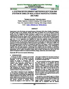
Fig. 3. Automated chip-pulling (Workpiece: low-carbon steel (JIS: S10C), Tool: cermet insert with guide grooves, nose radius of 0.4[mm] and rake angle of 0[deg], Feed: 0.16[mm/rev], Rotational speed: 215[rpm], Depth of cut: 0.3[mm])
3. Automated Chip Pulling 3.1. Realization of Automated Chip Pulling In order to demonstrate performance of the chip pulling system and effect of chip pulling in conventional turning, experiments are conducted at 2 different pulling speeds and presented in Fig. 3. Original chip flow speed is measured as 16[m/min] at the cutting speed of 76.7[m/min] for this process. Chip pulling cutting is performed by setting roller speed to 20[m/min] and 35[m/min], respectively. Once the chip is guided, it enters the pulling device within 1[sec] from the start of cutting (see Fig. 3) and pulled smoothly without breaking it. By forcing the chip flow speed 1.25 times higher than its original value, i.e. pulling at 20[m/min], cutting forces are influenced slightly. By increasing the chip flow speed around 2 times higher than the original process, forces are reduced greatly. The effective (resultant) friction force component, which is defined as original friction force subtracted by the pulling force, is reduced by half, and thus the friction angle is altered from 35[deg] down to 22[deg]. Figure 3 also shows dynamic response of the cutting process to pulling speed/force command. Due to gear mechanism and inertia of the pulling system, chip flow speed can be controlled rapidly at a bandwidth of 102[rad/sec]. It has
4
B.Sencer, et.al./ Procedia CIRP 00 (2014) 000–000
been observed that the process responds to pulling force quickly following the speed change at least at a similar bandwidth. Actual pulling force is also measured during experiments from a force sensor mounted under the pulling device. As shown in Fig. 3, designed Kalman Filter can observe slowly varying chip tension accurately from noisy signals allowing a sensor-less operation and chip tension control. Finally, the reliability of the chip pulling system in terms of successful chip guidance is also tested. In this case, the navigation by controlling the chip flow angle is critical at the cutting point so that the cut chip reliably enters the guide tunnel. In the proposed system, the cutting tool has grooves on the rake face to guide the cut chip to the guide tunnel and towards the rollers. It is experimentally concluded that the chip navigation succeeded at various chip guide angles at a depth of cut of 0.2 mm and a feed rate of 0.06 mm/rev, where the original chip flow angle is not very large from the controlled chip flow angle. As the depth of cut and the feed rate increase, the original chip flow angle increases and the chip navigation tends to fail. The navigation was difficult especially at a depth of cut of 0.8 mm and a feed rate of 0.24 mm/rev, because the chip thickness becomes large.
3.2. Evaluation of the Process with Chip-pulling The effect of “chip pulling” is demonstrated briefly in the previous section through automated chip pulling experiments. As compared to conventional turning, in chip pulling turning, process forces can be minimized by applying tension on the cut chip. It allows real-time control of friction and shear angles directly without changing any of the predetermined cutting conditions. This section presents the pulling effect on the process parameters in more detail. The process with the pulling can be modeled based on the orthogonal cutting theory [10] with a thin shear plane. It can be assumed that when the chip is pulled, it directly cancels the friction force, Ffriction on the rake face by the amount of the chip tension, Fpull. This would rotate the shear plane and create a larger shear angle. On the other hand, considering the material flow, when the chip is pulled at a higher speed than its original flow, the thickness is reduced as also shown in the previous section. The new shear plane should then have a smaller shear area due the increased chip thickness ratio leading to reduction in all the process forces, and hence the normal, friction and resultant forces are lowered. Here, one critical parameter is the friction angle. As a matter of fact, the original friction angle associated with the cutting process is a function of the tool-material pair. However, when the chip is pulled, the pulling force directly cancels the friction force and generates a so-called “effective friction” angle, which is defined here as: ⎛F − Fpull ⎞⎟ ⎟⎟ β ' = tan−1 ⎜⎜⎜ friction (6) ⎟⎟ ⎝⎜ Fnormal ⎠ Based on the above relationship, change in the process parameters due to pulling as a function of the effective friction, β ' is computed. Results of the chip pulling turning measurements are summarized in Fig. 4. As shown, introducing controlled tension on the chip, the effective friction angle is reduced, the shear angle is increased and the process forces are reduced almost by half without changing any of the actual cutting parameters. It introduces an opportunity to cut in higher material removal rate and efficiency with lower forces. As the pulling force is increased, friction energy consumed by cutting is reduced dramatically. As noted from Fig. 4, the advantage obtained in reduction of cutting energy is more than 5 times than that of inputted by pulling. This in return reduces overall energy, heat generation and helps to improve tool life. Change in the chip colour indicates reduction in the cutting energy, and it is presented in Fig. 5. As shown, when the chip is pulled, its colour also changes from dark blue to gold and silver in accordance with the reduction in the cutting energy.
Fig. 4. Experimental results of chip-pulling turning process. (Workpiece: low-carbon steel (JIS: S10C), Tool: sintered tungsten carbide insert with guide grooves, nose radius of 0.8[mm] and rake angle of 0[deg], Feed: 0.12[mm/rev], Rotational speed: 215[rpm], Cutting speed: 133 [m/min], Depth of cut: 0.4[mm]) Fig. 5. Change in the chip color by chip-pulling. (For experimental conditions refer to Fig. 3)
B.Sencer, et.al./ Procedia CIRP 00 (2014) 000–000
4. Conclusions Automated chip pulling turning is presented in this paper. A chip-pulling device with a sensor-less pulling force monitoring function is developed to steadily insert tension on the guided chip and to attain high performance turning. It has shown that the cutting process can be controlled with quick response, which allows real-time regulation of the cutting forces through chip pulling force. Developed system demonstrated high performance turning with lower cutting forces and overall energy. It is expected that the developed turning system assisted with chip guiding and pulling can be applied to attain high performance turning with higher efficiency (higher speed/larger cutting area), higher chatter stability and better machining accuracy. References [1] Altintas Y, Weck M., 2004, Chatter stability in metal cutting and grinding, Annals of CIRP, 53/2:619–642.
5
[2] Liang, S. Y., Hecker, R. L., Landers, R. G., 2004, Machining process monitoring and control: the state-of-the-art, Trans. of ASME, J. of Manufacturing Science and Engineering, 126/2:297-310. [3] Kakinuma, Y., Sudo, Y., Aoyama, T., 2011, Detection of chatter vibration in end milling applying disturbance observer, Annals of CIRP, 60/1: 109– 112. [4] Shamoto, E., Moriwaki, T., 1994, Study on elliptical vibration cutting, Annals of CIRP, 43/1: 35-38. [5] Nakayama, K., 1964, Effect of tension applied to chip during metal cutting, Bull. JSPE, 30/1: 46-51. [6] Jawahir, I.S., Van Luttervelt, C.A., 1993, Recent developments in chip control research and applications, Annals of CIRP, 42/2: 659-693. [7] Shamoto, E., Aoki, T., Sencer, B., Suzuki N., Hino R., Koide, T., 2011, Control of chip flow with guide grooves for continuous chip disposal and chip-pulling turning, Annals of CIRP, 60/1:125-128. [8] Kalman, R.E., 1960, A new approach to linear filtering and prediction problems, Journal of Basic Engineering, 82:35–44. [9] Erkorkmaz, K., Altintas, Y., 2001, High speed CNC system design: Part II, Int. J. of Machine Tools and Manufacture, 41/10:1487-1509. [10] Altintas, Y., 2000, Manufacturing automation: metal cutting mechanics, machine tool vibrations, and CNC design, Cambridge University Press.