The 28th Computational Fluid Dynamics Symposium C08-1
Development of an Effective Implicit Solver for General-Purpose Unstructured CFD Software o Yoshitaka Nakashima, Software Cradle Co., Ltd, Umeda Kita-ku, Osaka, E-mail:
[email protected] Norihiko Watanabe, Software Cradle Co., Ltd, Umeda Kita-ku, Osaka, E-mail:
[email protected] Hiroaki Nishikawa, National Institute of Aerospace, Hampton, VA, USA, E-mail:
[email protected] In this paper, we report the development of an effective implicit finite-volume solver for general-purpose turbulent flow computations on unstructured hybrid mesh system. For the inviscid and viscous fluxes, we employ the Rotated-Roe-HLL and alpha-damping fluxes, respectively. The implicit solver is constructed by a defect correction method, where the residual Jacobian is constructed based on a low-order compact scheme. It enables efficient time-dependent computations by an unconditionally-stable implicit time-integration scheme. Numerical results show that a significant speed-up is achieved over an explicit pseudo-time stepping scheme and the exact first-order inviscid Jacobian gives superior iterative convergence over a simplified inviscid Jacobian for both steady-state and transient analyses.
1. Introduction This paper reports further improvements made to the density-based solver recently added to our general-purpose unstructured-mesh CFD software, SC/Tetra. The density-based solver is constructed based on the second-order node-centered edge-based discretization with recently developed inviscid and viscous fluxes: Rotated-Roe-HLL (Rotated-RHLL) flux,(1) which is found robust for shock instabilities without compromising the accuracy, and the alpha-damping viscous flux,(2) which has been shown to be one of the most robust and accurate schemes among various viscous schemes tested for unstructured grids.(3) As reported previously, the density-based solver enables robust and accurate inviscid shock wave and viscous turbulent computations.(4) However, the explicit time-integration scheme employed in the solver, although it can still be used for some practical turbulent computations, is not efficient enough as a general-purpose solver, especially for steady-state analyses and for problems requiring a robust and efficient implicit time-integration scheme. Since the implicit time stepping scheme is built upon a steady-state (nonlinear) solver, which is used to solve the implicit residual equations over each physical-time step, a major enhancement is made in both aspects by the implementation of an implicit steady solver.
computations by an implicit time integration scheme. In either case, therefore, a robust and efficient nonlinear solver is required.
2. Discretization The discretization is performed by the second-order node-centered edge-based method, where the solution values are stored at nodes, the gradients are computed by a linear least-squares (LSQ) method, and the flux balance is approximated by the edge-based quadrature formula with the numerical flux evaluated at the edge-midpoint. For the inviscid and viscous fluxes, we employ the Rotated-RHLL and alpha-damping fluxes, respectively. These numerical fluxes are evaluated by the left and right states linearly extrapolated to the edge-midpoint from the two end nodes of the edge to achieve second-order accuracy. See the previous paper(4) for more details. The discretization defines the residual at each node, yielding a global system of nonlinear residual equations: 𝑅(𝑈) = 0, where 𝑈 is the global solution vector and 𝑅 is the global residual vector. It needs to be solved to obtain a steady-state solution or to advance the numerical solution to the next physical-time step in unsteady 1
3. Implicit Defect-Correction Solver 3.1 Basic Construction One of the most powerful nonlinear solvers is Newton’s method, 𝑈 𝑘+1 = 𝑈 𝑘 +△ 𝑈, 𝜕𝑅(𝑈 𝑘 ) △ 𝑈 = −𝑅(𝑈 𝑘 ), 𝜕𝑈𝑘 where 𝑘 is the iteration counter and △ 𝑈 is the correction. In principle, it is capable of solving the residual equations to ‘machine zero’ within 10 iterations (quadratic convergence) for any size of the grid. For the second-order edge-based discretization, however, it is not a practical option because it requires a large amount of memory for storing the Jacobian matrix due to the non-compact stencil. An approximate but practical nonlinear solver can be constructed by a defect-correction (DC) approach. Namely, we replace the impractical exact Jacobian by an approximate Jacobian based on a low-order compact edge-based scheme, 𝜕𝑅′(𝑈 𝑘 ) △ 𝑈 = −𝑅(𝑈 𝑘 ), 𝜕𝑈𝑘 where 𝑅′ is the residual of a low-order scheme. Consequently, the quadratic convergence is lost, but it still provides a far superior convergence rate over a naive explicit solver. To construct the approximate Jacobian, we ignore all the LSQ gradients to define a compact first-order inviscid scheme and a compact (inconsistent) viscous scheme, and then exactly differentiate the resulting low-order residual. For the Rotated-RHLL flux, which is a combination of the Roe and HLL fluxes, the Jacobian matrix is constructed by exactly differentiating the Roe flux and the HLL flux. As a simpler but practical option, we also consider the exact Jacobian of the Rusanov flux, which is a very dissipative flux based on a scalar dissipation term.(1) For the viscous flux, the Jacobian is constructed by exactly differentiating the alpha-damping flux. Since all the LSQ gradients are ignored, we construct the viscous Jacobian by differentiating only the damping term of the alpha-damping flux. The damping term by itself does not consistently approximate the viscous flux, and therefore it is an inconsistent scheme (but often used in unstructured solvers for the sake of robustness). Here, we employ the inconsistent scheme only for the Jacobian construction; we have the alpha-damping flux with all the LSQ gradients in the residual (i.e., the Copyright © 2014 by JSFM
The 28th Computational Fluid Dynamics Symposium C08-1 iterative solution difference.
right hand side) to guarantee the consistency and accuracy. Note that the damping term is critical to the construction of an implicit solver; the differentiation of the low-order viscous flux would yield nothing without the damping term. The flux Jacobians have been derived analytically and hand-coded. It is possible to employ a numerical differentiation technique such as the automatic differentiation. However, the hand-coded Jacobians are computationally much cheaper and therefore suitable for developing an efficient solver. As well known, the construction of Newton’s method is possible by a Jacobian-free Newton-Krylov method. But it can be a practical method only if an effective preconditioner is available. The implicit DC solver described here is expected to serve in future as an effective preconditioner for a practical Jacobian-free Newton-Krylov solver.(5)
4. Time Integration Scheme Time integration is performed by the second-order backward difference formula (BDF2): 𝜕𝑈 3𝑈 𝑛+1 − 4𝑈 𝑛 + 𝑈 𝑛−1 ≈ , 𝜕𝑡 2Δ𝑡 where Δ𝑡 is the physical-time step; the discretized time derivative is incorporated into the residual 𝑅 as a source term. This scheme is unconditionally-stable, and therefore the physical time step can be determined solely by physical requirements, not by numerical stability requirements. This is a very attractive property for general-purpose unstructured CFD software. In fact, BDF2 has been very widely employed in many practical CFD codes. The implicit time integration requires the solution of a nonlinear system of equations, 𝑅(𝑈 𝑛+1 ) = 0, at every physical-time step. The nonlinear problem is equivalent to a pseudo-steady problem, and can be solved by marching in the pseudo-time with an explicit time-stepping scheme. The resulting algorithm is often called the dual-time stepping method. But the explicit pseudo-time stepping towards the pseudo-steady state can be very expensive since it typically requires a large number of time steps and thus a large number of nonlinear residual evaluations. To solve the nonlinear system efficiently, we employ the implicit DC solver as described in the previous section. For the transient analysis considered in this study, the CFL number associated with the pseudo-time step is fixed to be 105. Note that the algorithm is not the dual-time stepping method since the implicit DC solver is not a pseudo-time stepping scheme.
3.2 Linear Relaxation The resulting linear system is not fully solved but relaxed to reduce the linear residual by two orders of magnitude. Currently, a sequential block Gauss-Seidel (GS) relaxation scheme is applied within each partition. Further improvements will be made in future by implementing a multi-color GS relaxation, which is expected to yield partition-independent convergence in a parallel environment. Although it is not used in this study, it is possible and often helpful to introduce an under-relaxation parameter in the linear relaxation. 3.3 Adaptive Strategies The implicit DC solver is an iterative nonlinear solver, and not a pseudo-time stepping scheme. However, it is often useful to incorporate pseudo-time derivative terms based on a local pseudo-time step, which is added in the diagonals of the Jacobian matrix, to improve the diagonal dominance: (
5. Results 5.1 RAE2822 Transonic Airfoil To demonstrate the effectiveness of the developed implicit solver, we
𝑉 𝜕𝑅′(𝑈 𝑘 ) + ) △ 𝑈 = −𝑅(𝑈 𝑘 ), △𝜏 𝜕𝑈𝑘
(a) Pressure
where 𝑉⁄Δ𝜏 is a diagonal matrix of the ratio of the local control volume to the local pseudo-time step. It is expected to stabilize the linear relaxation and the nonlinear iteration. The CFL number associated with the pseudo-time step is ramped from an initial value, typically 1, and to the maximum value of 105 with an increment of 20% in each iteration. To deal with unexpected instability during the iteration, an under-relaxation parameter is introduced; a maximum change on the order of 20% is allowed for the density and total energy in the each iteration.(5) The Rotated-RHLL flux involves a parameter that determines the weights assigned to the Roe and HLL fluxes. The parameter is updated at every iteration during the first 50 iterations, and then updated at every 20 iterations thereafter. The Rotated-RHLL Jacobian is truly exact when the parameter is frozen.
(b) Mach number
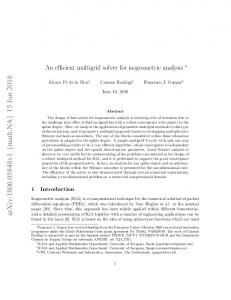
Fig. 1 Pressure and Mach number distributions around RAE2822 airfoil
3.4 Convergence Criteria Convergence is checked by the difference of two successive solutions (the iterative solution difference) of the primitive variable, such as density, pressure, and velocities, being less than a specified tolerance. In this study, the iterative solution difference is normalized by the difference between maximum and minimum values of the variable in the computational region, and the tolerance is set to be 10-6. For the problems considered in this paper, the above stopping criterion was found practical. However, to avoid possible false terminations by slow or stalled convergence, the residual should be monitored in general, instead or in addition to the 2
Fig. 2 Pressure coefficients on the RAE2822 airfoil Copyright © 2014 by JSFM
The 28th Computational Fluid Dynamics Symposium C08-1 the steady state is taken to be reached at the iterative pressure difference being less than 10-6 for convenience. As shown in the table and figure, the implicit solver achieves a rapid convergence and an order of magnitude speed-up in the calculation time over the explicit pseudo-time stepping scheme. Furthermore, the Rotated-RHLL Jacobian (the exact first-order inviscid Jacobian) gives superior iterative convergence and approximately 2.5 times faster in the calculation time than the Rusanov Jacobian.
consider a transonic turbulent flow over the RAE2822 airfoil. The Mach number is 0.729, the Reynolds number is 6.5 million, and the angle of attack is 2.31 degrees. The turbulence model is SST k-omega.(6) The grid is fully unstructured with 93,297 prismatic and hexahedral elements and 100,626 nodes, where 50,313 nodes exist on the two-dimensional plane and hexahedral elements are used only around the airfoil. We employ the Rotated-RHLL flux in the residual, and apply the three types of explicit/implicit solvers: the explicit pseudo-time stepping method, the implicit DC solver with either the Rusanov or Rotated-RHLL Jacobians. For the explicit method, the CFL number of pseudo-time step is fixed to be 0.8. The same steady state is expected for these three methods. As an example, the pressure and Mach number distributions around the airfoil obtained by the implicit DC solver with Rotated-RHLL Jacobian are shown in Fig. 1. Figure 2 shows the pressure coefficients on the airfoil in comparison with the experimental result.(7) As expected, the pressure coefficients are almost the same between the three methods. Furthermore, they are in good agreement with the experimental result. Table 1 shows the calculation time and the convergence cycle in each method. Note that one cycle corresponds to one pseudo-time step or one DC iteration. Here, the computations were performed with 24 CPU cores. Figure 3 shows histories of the iterative pressure difference. Note that, for this problem,
5.2 Flow around Cylinder We consider a time-dependent laminar flow over a cylinder to examine the efficiency of the implicit time stepping scheme built upon the implicit DC solver. The Mach number is 0.2 and the Reynolds number is 150. The grid is fully unstructured with 50,875 prismatic and hexahedral elements and 51,566 nodes, where 25,783 nodes exist on the two-dimensional plane. For this problem, we compare the performance of a two-stage second-order explicit Runge-Kutta time stepping method, and the BDF2 scheme with the explicit pseudo-time stepping method and the implicit DC method. Note that, in this problem, we employ the Roe flux in the residual. As for the Jacobian matrix in the implicit DC solver, we apply the Roe and Rusanov Jacobians. At every physical time step, the implicit residual equations are solved until the iterative differences of the
Table 1 Calculation time by 24 CPU cores parallel computation for RAE2822 airfoil Solver Explicit pseudo-time stepping Implicit DC with Rusanov Jacobian Implicit DC with Rotated-RHLL Jacobian
Calculation time [sec]
Total cycles
Total
1 cycle
29,649
3,386
0.11
442
302
0.68
109
125
1.15
Fig. 4 Vorticity distribution around a cylinder
Fig. 3 Histories of the iterative pressure difference for RAE2822 airfoil
Fig. 5 Time histories of lift coefficient acting on the cylinder, where t1 is the time of a peak value
Table 2 Calculation time by 24 CPU cores parallel computation for flow around a cylinder Solver Physical-time stepping
Calculation
Physical-time
Nonlinear Solver
cycles
step
418,569
0.0019
Explicit Runge-Kutta
None
Second-order backward
Explicit pseudo-time stepping
difference formula
Implicit DC with Rusanov Jacobian
(BDF2)
Implicit DC with Roe Jacobian
2,000
0.4000
3
Inner iterative CFL
loops at every time step
0.8 167.4
Calculation time [sec] Total
1 cycle
None
11,432
0.03
127.1
6,541
3.27
9.4
2,351
1.18
6.7
1,556
0.78
Copyright © 2014 by JSFM
The 28th Computational Fluid Dynamics Symposium C08-1 6. Conclusions An efficient implicit solver has been developed for the density-based compressible-flow solver for unstructured-mesh CFD software. The method is a DC method based on the exact first-order Jacobian for the inviscid terms and the exact Jacobian for the damping term of the alpha-damping scheme for the viscous terms. Significant speed-up has been demonstrated over an explicit pseudo-steady solver for simple but realistic steady turbulent flow and fundamental transient laminar flow cases on unstructured grids.
conservative variables drop below10-6. As an example, the vorticity distribution around the cylinder obtained by the BDF2 scheme using the implicit DC solver with the Roe Jacobian is shown in Fig. 4. Figure 5 shows the time histories of lift coefficient acting on the cylinder. The lift coefficients are almost the same among the four methods. Table 2 shows the calculation time and the number of inner iterative loops at every physical-time step in each method. Since all the methods solve the same physical-time length, the explicit Runge-Kutta method requires a huge number of cycles (physical-time steps) because of a tiny time step due to the CFL condition; therefore the computational cost is very high. On the other hand, a large time step is available in the BDF2 scheme. The number of inner iterative loops for the DC solver is significantly smaller than that of the explicit pseudo-time stepping. Furthermore, the Roe Jacobian, which is the exact first-order inviscid Jacobian, gives superior inner-iterative convergence over the Rusanov Jacobian; consequently, it achieves the shortest calculation time among the methods considered, which is nearly one order of magnitude faster than the explicit time stepping scheme.
Bibliography (1) Nishikawa, H. and Kitamura, K., “Very simple, carbuncle-free, boundary-layer-resolving, rotated-hybrid Riemann solvers,” J. Comp. Phys., 227: 2560-2581 (2008). (2) Nishikawa, H., “Two ways to extend diffusion schemes to Navier-Stokes schemes: gradient formula or upwind flux,” AIAA Paper, 2011-3044 (2011). (3) Jalali, A., Sharbatdar, M., and Ollivier-Gooch, C., “Accuracy analysis of unstructured finite volume discretization schemes for diffusive fluxes,” Comput. Fluids, 101: 220-232 (2014). (4) Nakashima, Y., Yoshida, H., Watanabe, N., and Nishikawa, H. “Development of a robust and accurate general-purpose compressible flow solver for unstructured meshes,” The 26th Computational Fluid Dynamics Symposium, Tokyo, Japan (2012). (5) Nishikawa, H., Diskin B., Thomas, J. L., and Hammond, D. P., “Recent advances in agglomerated multigrid,” AIAA Paper, 2013-863 (2013). (6) Menter, F. R., “Zonal two equation k-ω turbulence models for aerodynamic flows,” AIAA Paper, 93-2906 (1993). (7) Cook, P. H., McDonald, M. A., and Firmin, M. C. P., “Aerofoil RAE2822 - pressure distributions, and boundary layer and wake measurements,” AGARD Report AR 138 (1979). (8) http://aaac.larc.nasa.gov/tsab/cfdlarc/aiaa-dpw/ (9) Spalart, P. R. and Allmaras, S. R., “A one-equation turbulence model for aerodynamic flows,” AIAA Paper, 92-0439 (1992).
5.3 NASA CRM We consider a three-dimensional turbulent flow over NASA’s Common Research Model (CRM)(8) to investigate the parallel efficiency for realistic computations. The Mach number is 0.85, the Reynolds number is 5 million, and the angle of attack is 2 degrees. The turbulence model is Spalart-Allmaras.(9) The computational domain is half of the full three-dimensional domain. The grid is fully unstructured with 8,266,407 tetrahedral and prismatic elements and 1,737,014 nodes. We employ the Rotated-RHLL flux and its Jacobian to the residual and implicit DC solver, respectively. As shown in Fig. 6, the steady state can be obtained by the implicit approach even for the realistic three-dimensional geometry. Figure 7 shows a good parallel efficiency for this problem.
Fig. 6 Body surface pressure and iso-surfaces of Mach 1 for NASA CRM
Fig. 7 Measurement of parallel efficiency for NASA CRM 4
Copyright © 2014 by JSFM