EnviroInfo 2009 (Berlin) Environmental Informatics and Industrial Environmental Protection: Concepts, Methods and Tools Copyright © Shaker Verlag 2009. ISBN: 978-3-8322-8397-1
Development of simulation components for material flow simulation of production systems based on the plugin architecture framework EMPINIA P. Jahr, L. Schiemann, V. Wohlgemuth HTW Berlin, University of Applied Science, Department of Engineering II Industrial Environmental Informatics Unit Wilhelminenhofstr. 75A, D-12459 Berlin, Germany
[email protected] [email protected] [email protected] Abstract This paper gives an overview on the design and development of simulation components for production systems using the open-source software framework EMPINIA. These components (e.g. machines, transport devices, storages) are created in the course of the EMPORER project, which is funded by the German Ministry for Education and Research (BMBF). The goal of this project is to provide an open-source framework for a fast, easy and lightweight development of applications in the field of environmental management information systems (EMIS), including a detailed support for the solution of certain domain specific problems (e.g. material flow analysis, simulation, handling of hazardous materials etc.). As a part of the EMPORER project an EMPINIA-based material flow simulator called MILAN is developed. It incorporates a discrete event simulation infrastructure with material accounting and management functionality. The goal of this development lies on extensibility of existing simulation an material accounting functionality. Thus new simulation functions and components should easily be added, exchanged or recombined with minimal effort. The concept of material flow simulation combines the approach of production-oriented, order-related simulation and material flow analysis for the application field production systems. To use simulation components for material flow simulation purposes, these components must support both perspectives. This paper covers the structure of the developed production system components in detail as well as the EMPINIA architecture and the material flow simulator MILAN.
1. Motivation The rational use of goods, such as the production, consumption and distribution is widely known as economic activity. Its improvement is directly connected to the in- and output relations and consists of the attempt to get more returns while investing lesser resources. (cf. Wöhe et al. 2008). This process is also called optimization and it is target-oriented (e.g. optimizing the costs, quality, efficiency or effectiveness). Optimizations can be achieved using an operations research approach (cf. Domschke et al. 2008). The more complex and detailed a system is the less probable is the achievement of an optimized result within the boundaries of an average time frame using methods from operations research (e.g. the problem of “Traveling Sales Man”). In these cases, the usage of simulation methods can be an adequate approach. The result determined by simulations is possibly not the optimum. However approximated results can be deduced. Simulations can help to analyze and understand the behavior of a system and therefore allow the user to play with a model of a real world system to find a result that is relative close to the optimum. One field of interest which is not a common part of economical simulation efforts yet is the simulation and optimization of material flows (cf. Wohlgemuth 2005). In a production system there are raw materials converted to salable goods with the help of energy, auxiliary materials or other supplies. Furthermore some unintended products like waste and emissions are produced. These materials pass through different stages of the value chain. Raw materials are delivered, processed by machines or workers, combined to products, packed and finally shipped to customers. Working items are stored, transported, sold, used and sooner or later consumed or rather taken out of order and disposed. During
151
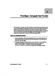
the moddeling phase of productioon systems thhese processses are modeeled using seeparated com mponents, which caan be labeledd as buildingg blocks. Thhese compon nents represennt the elemeents (e.g. maachines) a product has to pass within his production liffe cycle. Theese workstattions, the woorking items,, workers m become enttities of the correspondinng model (aas long as and any other constiituent part of the system y is focusing on). They aare designed to be pathey are relevant forr the goals a certain simuulation study rameterized by the modeler m in thhe course off simulation experimentss. Most of thhe currently used u methods to simulate prooduction systtems are disccrete event-b based and proocess-based simulations (cf. Page et al. 20005). Typiccal simulationn software in i the field of o optimizattion of produuctions doess not offer options o to considerr environmenntal and ecoonomical gooals togetherr based on one consisteent model (e.g. high adherencce to deliverry dates, shoort throughpuut time, high h workload, low l stocks). Energy and d material consumpptions per prroduction proocess are norrmally not reepresentable with low eff ffort (cf. Woh hlgemuth 2005). To T face thiss problem, the t concept of a discrette event-bassed material flow simullator was developeed, which inttegrates the material m flow w perspective with the joob-orientatedd simulation approach for prodduction system m. Thus a simulation ruun can comp pile results thhat are relevvant for the economic e behaviorr as well as results r that describe the im mpacts of th he productionn system undder examinatiion to the environm ment (cf. Woohlgemuth 20005, Wohlgeemuth et al. 2006). 2 This enables e the assistance of operative decisions with strateegic and tacctical consideerations for both econom mical and ennvironmentaal aspects (see Figuure 1). To seet the conceppt of MILAN N on a stabble and new basis and to use the addvantages off modern softwaree paradigms (e.g. reuse, platform p inddependence, modularity, individual pproduct desig gn by the user) the
Figuree 1: Environm mental and ecconomic goal system (cf. Košturiak K et aal. 1995)
described approach is i currently further deveeloped in thee course of thhe EMPORE ER4 project. The new developm ment of the material flow simulator MILAN is based on thhe open-sourrce plugin framework EMPINIIA5 (comparaable to the Java J framew work Eclipse6). EMPINIA A, which is aalso develop ped in the course of o the EMPO ORER project, is designed for the dev velopment of complex ddomain-specific applications especially e inn the field off environmenntal managem ment information system ms (EMIS) (ccf. Wohlgemuth et al. 2008).. It is a com mponent-orienntated extenssible applicaation framew work based on o Micro-
4
http://ww ww.emporer.nett http://ww ww.empinia.orgg 6 http://ww ww.eclipse.org 5
152
Copyright © Shaker Verlag 2009. ISBN: 978-3-8322-8397-1
softs.NET7 technology with the purpose to support and simplify the development of complex software systems.8 For MILAN it is necessary to provide libraries of simulation components (e.g. for production systems: machines, transporters, system boundaries) which enable the modeler to represent and simulate his system adequately. These components can be added to an application i.e. as building blocks via a plugin mechanism and thus can be used to build a user-specific model. This may lead to an easy development of user-specific components with low dependencies and an attachment to a modeling tool box for a certain application field, which is not possible with other simulation tools (cf. Page et al. 2000 & 2005). These components can either be generally applicable or might be used for very specialized purpose. Specialized entities are developed for a whole production sector (e.g. semi-conductor sector with coater, stepper and dispatcher) (cf. Wohlgemuth et al. 2004 & 2005) or they represent a production component of a certain company with its specific parameters. In contrast general components are highly abstracted and are applicable for many production systems (cf. Jahr et al. 2009). The goal of this project was the development and implementation of such general entities for MILAN. In this sense this paper describes the components, a.k.a. plugins, which build MILAN besides EMPINIA and explains the development and structure of general production system entities. It further presents how the discrete event simulation for material flows as well as the modeling within the MILAN software works.
2. MILAN The material flow simulator MILAN is build upon a set of highly specialized extensions for the plugin framework EMPINIA. Besides the components which come with EMPINIA there are many plugins taken from the EMIS toolbox and combined with MILAN. These are shown in Fehler! Verweisquelle konnte nicht gefunden werden.. Furthermore it is shortly explained how these plugins are sticked together. The simulation capabilities of the MILAN software consist of the following elements: • The simulation core consists of the central simulation service, interfaces and abstract base classes for models, experiments and model entities. These are used in each kind of simulation. The simulation service provides models and experiments in a way that other software parts can use them. The simulation core gives models and their entities access to the functionality of a domain model service. A domain model defines the domain of an EMPINIA-based application, its elements and their relations as well as rules that apply to this domain. MILAN consists of the domain 'simulation' with elements like 'model' and 'entity'. Among other important functionalities the domain service provides possibilities to persist its elements. That is the reason why this service is used in MILAN to save and load formerly created models. • A bundle for discrete event simulation extends the simulation core with classes specific to the discrete event simulation approach. These classes are using an EMPINIA extension that enables the development of logical graphs in order to combine entities of a model to a network diagram. The basic generic experiment component is extended with an event list and a scheduler, which are used to simulate time in discrete steps. • The simulation components have access to many stochastic distributions (e.g. Normal, Bernoulli). They are used to generate streams of random numbers, for example to schedule an event which follows a certain arrival probability. Additional to these existing distributions user-defined distributions can also be added via plugins.
7
http://msdn.microsoft.com/de-de/netframework/default.aspx More information about the design of applications with EMPINIA can be found in this book in the article: Conceptual Design and Implementation of a Tools Platform for the development of EMIS based on the open-source plugin-framework Empinia. 8
153
Copyright © Shaker Verlag 2009. ISBN: 978-3-8322-8397-1
Figure 2: 2 MILAN coomponents (ccf. Wohlgemu uth 2005)
N software co onsist of the following ellements: The matterial flow caapabilities off the MILAN • A maaterial manaagement com mponent alloows creating, deleting annd organizingg materials as a well as bill of o materials. A user interfface view forr this kind off data is addeed through w which the mo odeler can show w and manipuulate these iteems. • The material m acccounting syystem accesses the materrial managem ment to add or remove a custom amouunt of materials of a certaain type. By its i means it is i possible too show, save and managee material and energy e bookkkeeping resuulting from thhe simulation n. Accountinng rules definne these bookkeeping whichh can be addded by the user u to all kinnd of discrette events in combinationn with relevaant model compponents. Defi finition and structure s of rules r are defiined with help of the exttension mech hanism as extennsions. Afterw wards these rules can bee used and co onfigured. Foollowing thee observer deesign pattern which w is usedd by the mateerial accountting system the t simulatioon componennts do not 'kn now' anythingg about materrial flows andd the bookkeeeping of maaterial input and a output ddata. Thus a developer d of sim mulation moodel components does noot necessarily y have to coonsider these mechanisms. Indeed the siimulation opperates indeppendently of any materiaal bookkeepinng issues. Thhe material flow f system juust listens too the simulatiions progresss and reacts to t occurring events if onee of its rules applies. The com mmon featurees of the MIL LAN softwarre consist of the t followingg elements: • Graphhical manipuulation of buuilding blockks leads to a faster deveelopment of a model. Th he graph editoor can be used to manippulate and crreate modelss. The editorr itself can w work in diffferent domains. Domain sppecific functtionality and the graphicaal representaation have to be defined by b plugin devellopers enabliing the editoor to handle new n domains and their components, c which are also a using plugiin definitionss. • Maniipulating moodel parameteer for the sim mulation and d material floow perspectiive is done by b means of prroperty editoors enablingg a simple annd consistent way of settiing values foor all types of o properties. For F the prodduction systeem domain there t are staandard editorrs implemennted. These allow a the changge of component specificc parameters like setting distributionss, accountingg rules, queu ue lengths or cappacities etc.
154
Copyright © Shaker Verlag 2009. ISBN: 978-3-8322-8397-1
• No analysis can be done without results. These are shown in reports which can be designed with the help of the reporting system. The data for the reports is aggregated during simulation runs by a system of observers that listen to changes in the material accounting and simulation entities.
Figure 3: Screenshot of MILAN application based on EMPINIA
An example of the graphical interface that users will get with MILAN is shown in Figure . You can see the simulation explorer with all the model components on the left side, below an overview map of the current model; in the middle the model editor with all available model entities in the toolbar, below a list of events which are currently scheduled; the experiment control for setting experiment parameter on the right side above a property editor for parameter setting of a model component (currently a workstation is selected). The execution of a material flow simulation requires the development of a model that represents the system under investigation. Up to now this requires two models, one for the material flow analysis and another one for the simulation-related aspects. The material flow simulator MILAN however is able to integrate both specific views into one model. It retains the common model structures and adds the different sets of parameters. These parameters like sets for material accounting or probability distribution streams can be added subsequently to the build a model structure. The modeling is done using a graphical network consisting of nodes and edges. The nodes describe important model elements, where products are handled or stay for processing for a certain period of time. Edges work as logical connections between these elements and are also intended to show the process flow direction. Once the modeling is complete the parameterization of the particular stations can be started. Depending on a specific model element these parameters can be very different from each other. Workstations for example have a processing-time, conveyors a loading and transportation time. In cases where no suitable standard component to represent the actual system can be found, new components can be added using the extension mechanism. This enables developers to create their own components or to use component libraries from other parties. The modeling of material and energy flows is done with the help of appropriate rules. According to these rules a certain set of materials is accounted depending
155
Copyright © Shaker Verlag 2009. ISBN: 978-3-8322-8397-1
on the occurrence of previously assigned events. At the end of the modeling phase the duration of the simulation can be chosen. From material flow perspective this can be the same as a balancing period. As soon as the right model structure, parameters and times are configured the material flow simulation is ready for simulation experiments. Experimentation can be done by variation of parameters. This enables the user to experiment from the material flow perspective and the order-based simulation perspective at the same time using only one model and one application. Once a simulation ends its data can be visualized in a reporting view (e.g. balance sheets and simulation results). The user is now able to analyze if a simulation run is better than another.
3. Simulation components for production systems Based on the simulation infrastructure and the discrete event simulation approach the next step of the development of MILAN was the implementation of a component package (in EMPINIA terms, a 'bundle') for the simulation of production systems. The included components extend the existing infrastructure in different areas. It was necessary to introduce an extended type of model, which covers the specific requirements of the production system simulation. The production model structure is organized as a directed graph. The nodes of the graph represent stationary elements of the production system (e.g. workstations, conveyors, storages). The edges define the order of the elements and therefore define the way products can travel through the model. During a simulation the products are created inside the system and travel along the edges. Inside the stationary elements, products can be transformed, removed and new ones can be created. Processes represented through stationary elements are modeled using samples of stochastic distributions for the duration of each process. When a process is finished the processed products are send to the next available stationary element. The ability to send and receive products is common to all stationary elements. While the simulation is running the internal behavior of a stationary element can lead to a state where it is temporarily unable to accept incoming products. At the current development stage, there are several states available, which can be used in stationary elements, like 'Failure', 'Maintenance' and 'Setup'. The number of these states and the activities that change them depend on the implementation of the stationary element component. The activities themselves are implemented as extensions and attached to the component extensions, so that new activities can easily be added and used for the development of new or more complex simulation components. At the moment there is a basic set of stationary elements implemented, which are offering a very broad set of capabilities for modeling and simulating production systems. The selection of these elements has been influenced by the work of Kosturiak et al. 1995, Wohlgemuth et al 2004 & 2005 and Banks et al. 2005. The current set of available stationary elements contains: • Workstations represent all types of machines, which perform tasks on products using a certain amount of simulated time. They can be configured to transform a set of products into another set using specific rules that define the amount of incoming and outgoing products. Workstations can break down (so the will be unavailable for a certain amount of time), can be maintained or can have a setup duration after they were activated or out of order. • Conveyors are one way to model the transport of products between stationary elements. The transport duration is the same for each product as long as no disturbance (failure, maintenance, all successors unavailable) occurs. These break down durations are added to the processing time. There are two different conveyor implementations – one which accumulates products at its end and one which completely stops the movement of products when blocked (downstream elements are unavailable). • Transporter systems define the second way of moving products between stationary elements. They use a configurable set of transport units (e.g. trucks) to transport products. Each transport process can take a different duration to finish. The transporters are so called resources that are defined inside the model using a resource pool. The resources of such a pool can be shared by several transporter systems.
156
Copyright © Shaker Verlag 2009. ISBN: 978-3-8322-8397-1
• Buffers are stationary elements that store products until they are needed by downstream stationary elements. They have a configurable capacity and become unavailable if this capacity is attained. • Synchronization points are stationary elements that can be used to combine parallel production chains or divide one stream of products into different chains using the same transformation rules that the workstation component uses. They use an internal queue to store products until a transformation rule can be satisfied. • Entry points define one kind of system boundary of a model. Entry points are creating products according to stochastic distributions (arrival times) and are feeding these products into the model. • Exit points mark the other kind of system boundary where products are removed after they completed their way through the production model. Both system boundaries will later be extended to act as points of intersection to a super ordinate model, if the containing model is itself a submodel and therefore has to act like a model component itself. To use one of the mentioned classes according to EMPINIAs extension mechanism, the class is appended with a .NET Attribute ('Extension'). In this way the EMPINIA-runtime environment can perceive it as extension of the simulations components. An example of the usage of the attribute in the C# programming language is shown in Figure . The identifier (Id) of the extension is communicated to the attribute via a parameter. Thus the Ids of the incorporating bundles as well as the extension points and the type are given to it. 1
[Extension(“Id of the extension”, “Id of the containing bundle”, “Id of the extension point”, typeof (Workstation)]
3
public class Workstation: StationaryElement, Iworkstation
4 5 6
{ ... }
Figure 4: Extension configuration of a stationary element (workstation)
Another option for this kind of definition is the possibility to write the extensions in xml-code. This can be done within the configuration/definition file of the bundles (Bundle.xml). Each extension point has an XML-schemata to validate the descriptions of the extensions. To be properly integrated into the simulation infrastructure the class has to implement various interfaces. Using a component via the interfaces enables the framework to use the component in different layers of the simulation domain. To be used in the production system domain for example, the component needs to be a simulation entity and therefore needs to implement the specific entity functions. It also has to support its usage in a net model which can be assured by implementing functions of a net node interface. As stated above the components representing stationary elements use a base class that models their common basic behavior. For their respective special possibilities they use a set of support classes. For example, these support classes extend the stationary elements to be able to fail during processing, to be able to be maintained or similar behaviors. Each support class models a specific state in which a stationary element can change during a simulation. Supports handle the creation of their related events (in most cases a start and end event, that turn the represented state on and off). When a component turns into the supported and state how long it remains in this state has to be defined in the owning component. The intention behind the partition of the simulation components into these support classes is the reuse of frequently needed functionality whose usage only differs in the way it is activated and deactivated.
157
Copyright © Shaker Verlag 2009. ISBN: 978-3-8322-8397-1
4. Conclusions and visions During the EMPORER project the plugin architecture EMPINIA was already developed. As a further result of the EMPORER project the material flow simulator MILAN was developed which is based on the EMPINIA software framework. New components for specific application areas are still under development. Another important result of the EMPORER project is the implementation of very abstract simulation entities for the analysis of production systems. These entities enable users to model and simulate a broad set of production systems. Because of their modularity and the plugin mechanisms of EMPINIA it is very easy to add more specialized entities to the production system’s domain and to use them for a material flow simulation. At the moment the production components are verified by performing a simulation study in a company that produces solar panels. The problems, results and experiences of this validation will be used to improve and enhance the components, the simulation infrastructure and MILAN as a simulation tool, itself.
Acknowledgement This research project is funded by the German Federal Ministry of Education and Research (BMBF). The authors thank for the support.
References Banks, J.; Carson II, J.S.; Nelson, B.L.; Nicol, D.M. (2005): Discrete-Event System Simulation. 4th Edition. Upper Saddle River. Pearson Prentice Hall, Upper Saddle River. Domschke, W.; Drexl, A. (2007): Einführung in Operations Research. 7th edition. Springer, Berlin. Hennig, M., Seeberger, H. (2008): Einführung in den „Extension Point“ - Mechanismus von Eclipse. In: Java Spektrum, 1/2008, p. 19-24 Jahr, P.; Schiemann, L.; Mäusbacher, M.; Panic, D.; Schnackenbeck, T.; Wohlgemuth V. (2009): Entwicklung von Produktionssystem-Komponenten zur Stoffstromsimulation auf Basis des OpenSource-Frameworks EMPINIA. In: Wittmann, J.; Flechsig, M. (Eds.): Simulation in Umweltund Geowissenschaften. Shaker Verlag, Aachen, p. 57-69 König U., Denz N., Schnackenbeck T., Mäusbacher M. (2009): GUI-Entwicklung mit Empinia - Einführung in ein erweiterbares Framework. dot.net-Magazin 5/2009, p.28-32 Košturiak, J.; Gregor, M. (1995): Simulation von Produktionssystemen. Springer Verlag, Wien. Law, A.M., Kelton, W.D. (2000): Simulation Modelling and Analysis. 3rd edition. McGraw-Hill, Boston. Marquardt, M.; Völter, M. (2003): Plugins - Anwendungsspezifische Komponenten. In: Java Spektrum, 2/2003, p. 20-26 Page, B.; Lechler, T.; Claassen, S. (2000): Objektorientierte Simulation in Java mit dem Framework Desmo-J. Libri Books, Hamburg. Page, B.; Kreutzer, W. (2005): The Java Simulation Handbook: Simulating Discrete Event System with UML and Java. Shaker Verlag, Aachen. Panic, D.; Schnackenbeck T.; Wohlgemuth V. (2008): Erweiterung eines Open Source Rahmenwerkes um Simulationsfunktionalität für betriebliche Umweltinformationssysteme. In: Wittmann, J., Wohlgemuth, V. (Eds.): Simulation in den Umwelt- und Geowissenschaften. Shaker Verlag, Aachen, p. 127-137 Rautenstrauch, C. (1999): Betriebliche Umweltinformationssysteme, Springer, Berlin. Schnackenbeck, T.; Panic D.; Wohlgemuth V. (2007): Eine offene Anwendungsarchitektur als Fundament eines Methodenbaukastens für betriebliche Umweltinformationssysteme. In: Wittmann, J., Wohlgemuth, V. (Eds.): Simulation in den Umwelt- und Geowissenschaften. Shaker Verlag, Aachen, p. 49-59 Wöhe, G.; Döring, U. (2008): Einführung in die Betriebswirtschaftslehre. 23th edition. Vahlen, München.
158
Copyright © Shaker Verlag 2009. ISBN: 978-3-8322-8397-1
Wohlgemuth, V.; Page, B.; Mäusbacher, M.; Staudt-Fischbach, P. (2004): Component-Based Integration of Discrete Event Simulation and Material Flow Analysis for Industrial Environmental Protection: A Case Study in Wafer Production, in: Proceedings of the 18th International Conference for Environmental Protection, October 21-23, CERN, Geneva, p. 303-312 Wohlgemuth, V. (2005): Komponentenbasierte Unterstützung von Methoden der Modellbildung und Simulation im Einsatzkontext des Umweltschutzes. Shaker Verlag, Aachen. Wohlgemuth, V.; Kreutzer, W.; Page, B. (2006): Combining discrete event simulation and material flow analysis in a component-based approach to industrial environmental protection. In: Environmental Modelling & Software. Elsevier, New York, p. 1607-1617 Wohlgemuth, V.; Schnackenbeck, T.; Panic, D.; Barling, R.-L. (2008): Development of an Open Source Software Framework as a Basis for Implementing Plugin-Based Environmental Management Information Systems (EMIS) In: Möller, A.; Page, B.; Schreiber, M. (Eds.): EnviroInfo 2008 - Environmental Informatics for Environmental Protection. Proceedings of the 22nd International Conference Environmental Informatics - Informatics for Environmental Protection, Sustainable Development and Risk Management, September 10-12, 2008, Leuphana University Lüneburg. Shaker Verlag, Aachen, p.584-592 Wolfinger, R.; Ghungana, D.; Prähofer, H.; Mössenböck, H.P. (2006): A Component Plug-In Architecture for the .NET Platform. Proceedings of the Joint Modular Languages Conference 2006, Oxford, UK, September 2006, LNCS, Volume 4228, Springer-Verlag, p. 287-305 Züllighoven, H. et al. (1998): Das objektorientierte Konstruktionshandbuch nach dem Werkzeug & Material-Ansatz, d-punkt, Heidelberg.
159
Copyright © Shaker Verlag 2009. ISBN: 978-3-8322-8397-1