Emil Veg Department for Theory of Machines and Mechanisms, Faculty of Mechanical Engineering, University of Belgrade
Mladen Regodić Department for Theory of Machines and Mechanisms, Faculty of Mechanical Engineering, University of Belgrade
Aleksandra Joksimović Student, Faculty of Mechanical Engineering, University of Belgrade
Nenad Gubeljak Faculty of Mechanical Engineering, University of Maribor Slovenia
Development of the Transmission Tower Virtual 3D Model for Structural Analysis in ANSYS This paper describes a methodology for transmission tower 3D modelling. The task was to develop a virtual 3D model, corresponding to the real structure, which will be subjected to structural analysis in ANSYS software. The process of 3D modelling is crucial for this kind of computer analysis. It requires precise key point coordinates defining. Not only the important points of the structure, but also the points of interest for the future structural analysis have to be defined. This means that model developer should be familiar with the structural analysis so he could form adequate key points in advance. The main point of the experiment concept is to determine dynamic behaviour of the structure, exposed to a known load. Truly correlated 3D model, with verified geometric, static and dynamic properties offers the opportunity to predict the structure behaviour under loads that can hardly apply on a living structure (extreme overloads, complex loads, and harsh ambient condition). Keywords: ANSYS, 3D model, structural analysis
1.
INTRODUCTION
Making a 3D model is a complex process of transformation of real structure into virtual model with necessary idealization. The starting points are geometry, supports, loads, expected displacements and deformations [1-3]. The starting point for structural and modal analysis is adequate virtual 3D model. Scientific paper [4] presents methods for 3D modelling of a machine in Solid Works Motion. It provides a good model for conducting static and dynamic analysis of desired machine at the very beginning of development process. Those virtual analyses will show the potential behaviour of machine parts during exploitation [5-8]. Electric power transmission tower is a lattice steel structure. It is built out of, by size different, but standard shape `L` and `U` profiles. The first step in virtual model building is to form a matrix of key points. Key points are all spots of importance, like starting and ending point of every line, points of support, points where the load is applied, or points where two steel parts are bolted. The difficulty is that all key points must have distinguished address. It is formed by point coordinates in the Cartesian coordinate system. When all key points are defined, it is important to link them with lines. Every line presents one `U` or `L` profile on the real structure. When a line model is formed, an adequate cross section should be assigned to every line. That is how a virtual part is formed. Every virtual part must have material properties assigned (density, Young's modulus, Poisson's ratio...) [9]. After those Received: March 2016, Accepted: December 2016 Correspondence to: Dr Emil Veg Faculty of Mechanical Engineering, Kraljice Marije 16, 11120 Belgrade 35, Serbia E-mail:
[email protected] doi: 10.5937/fmet1702232V © Faculty of Mechanical Engineering, Belgrade. All rights reserved
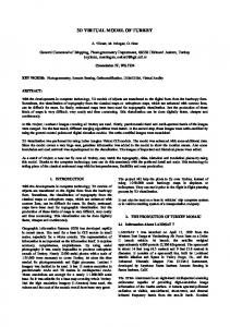
steps, a virtual model is ready for pre-processing. The tower consists of four main ‘L’ profiles, which start from the base plane, from the square vertices, and join, in a single point at the top of the tower. Between those main ‘L’ profiles, a side braces are bolted.
Figure 1. Real transmission tower structure
2.
KEYPOINTS DEFINITION
In order to form a correct key point matrix, it is necessary first to numerate all points. It has to be done, because, later, every line will be formed out of two key points (starting and ending keypoint), and every line that is formed will have its own number. In order to avoid confusion (more than three hundred and fifty points were made), and to be capable to meaningfully read analysis results, it is of extreme importance to do this numeration very carefully. FME Transactions (2017) 45, 232-235 232
It would be very hard to manually insert three coordinate values for every of 350 key points. That is why a small computer program was written, to automatically generate all needed key points. Idea was to use the theory of triangle similarity for generating key points. Eight base key points were defined manually. The base key points were defined through following command: K,1, 2.4, 0.3 , 2.4 K,2, 2.4, 0.3 , 0 K,3, 2.4, 0.3 ,-2.4 K,4, 0 , 0.3 ,-2.4 K,5,-2.4, 0.3 ,-2.4 K,6,-2.4, 0.3 ,0 K,7,-2.4, 0.3 , 2.4 K,8, 0 , 0.3 , 2.4
The letter `K` in at the beginning of the command line orders key point generation. The first number shows the key point address, and following three values represent key point coordinates in the Cartesian coordinate system. Graphically, the result is shown in Figure 2.
The following code was used to generate the keypoints on the four main ‘L’ profiles. It is a kind of ‘FOR’ loop, where the counter ‘j’ goes from 1 to 41. The letter ‘K’ defines key point generation. Then, there is a short code for key point address generation (J*BR+1). Then, three short codes that follow make the desired key point coordinates. BR=8 *DO,J,1,41 K,J*BR+1, Xj-((2.175*H(J))/36.7) , H(J) , Zj((2.175*H(J))/36.7) K,J*BR+2, Xj-((2.175*H(J))/36.7) , H(J) , 0 K,J*BR+3, Xj-((2.175*H(J))/36.7) , H(J) , (Zj((2.175*H(J))/36.7))*(-1) K,J*BR+4, 0 , H(J) , (Zj-((2.175*H(J))/36.7))*(-1) K,J*BR+5, (Xj-((2.175*H(J))/36.7))*(-1), H(J) , (Zj((2.175*H(J))/36.7))*(-1) K,J*BR+6, (Xj-((2.175*H(J))/36.7))*(-1), H(J) , 0 K,J*BR+7, (Xj-((2.175*H(J))/36.7))*(-1), H(J) , Zj((2.175*H(J))/36.7) K,J*BR+8, 0 , H(J) , Zj-((2.175*H(J))/36.7) *ENDDO
The result of this sub-program is shown in Figure 3.
Figure 2. Base key points
Next, a set of forty one variables that represent the height of future key points was defined. It was done by the following code:
Figure 3. Key points of four main ‘L’ profiles
In the same manner, all other key points were defi– ned. Final key point matrix is shown in Figure 4.
H(1) = 1.6 , 2.9 , 4.15 , 5.4 , 6.6 , 7.8 , 8.95 , 10.1 , 11.2 , 12.3 H(11) = 13.35, 14.4 , 15.4 , 16.4 , 17.35, 18.3 , 19.2 , 20.1 , 20.95, 21.8 H(21) = 22.6 , 23.4 , 24.15, 24.9 , 25.65, 26.4 , 27.15, 27.9 , 28.65, 29.4 H(31) = 30.05, 30.7 , 31.6 , 32.4 , 33.15, 33.85, 34.5 , 35.1 , 35.65, 36.15 H(41) = 36.7
Also, three variables, considering distances in the base plain, were defined. Xj=2.4 Yj=0 Zj=2.4 FME Transactions
Figure 4. Key points of four main ‘L’ profiles
VOL. 45, No 2, 2017 ▪ 233
Between those key points, both main lines and side braces were generated. 2.1 ASSIGNMENT OF CROSS-SECTION
In this process, a BEAM188 element was used. The BEAM188 element is suitable for analysing slender to moderately stubby/thick beam structures. This element is based on the Timoshenko beam theory. Shear defor– mation effects are included. BEAM188 is a linear (2-node) beam element in 3-D with six degrees of freedom at each node. The degrees of freedom at each node include translations in x, y, and z directions, and rotations about the x, y, and z directions. Warping of cross sections is assumed to be unrestrained. The beam elements are well-suited for linear, large rotation, and/or large strain nonlinear applications. BEAM188 includes stress stiffness terms, by default, in any analysis. The provided stress stiffness terms enable the elements to analyse flexural, lateral and torsional stability problems (using eigenvalue buckling or collapse studies with arc length methods). BEAM188 can be used with any cross section defined. Elasticity and isotropic hardening plasticity models are supported for calculations (irrespective of cross section subtype) [10]. With the following commands, used standard `L` profiles were configured in ANSYS: SECT,40,BEAM,L SECD,0.040,0.040,0.004,0.004
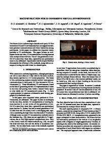
`SECT 40` is a code name for that kind of profile. It is of `L` shape (predefined in Ansys) and its dimen– sions are 40mm x 40mm, with wall thickness of 4mm. Similar code was written for the `U` shape cross section. After completion of the cross section assignment, a final result of a defined 3D model is shown in Figure 5.
definition of key points. Standard `L` and `U` profiles are modelled, and implemented in the line model. Everything described in text is also shown on corresponding figures. Finally, a fully defined 3D model of transmission tower, that is ready for static and dynamic analysis, is presented. ACKNOWLEDGMENT
Authors gratefully acknowledge the financial support from the Ministry of Education, Science and Technological Development of the Republic of Serbia under the projects ON174004 and TR35002. REFERENCES
[1] Maneski, T.: Computer modeling and structure calculations (in Serbian), University of Belgrade, Faculty of Mechanical engineering, Belgrade, 1998. [2] Petrović B., Petrović A., Ignjatović D., Grozdanović I., Kozak D., Katinić M.: Assessment of the maximum possible extension of bucket wheel SchRs740 boom based on static and dynamic calculation, Technical Gazette, Vol. 23, No 4 (2016), pp. 1233-1238. [3] Tatić U., Čolić K., Sedmak A., Mišković Ž., Petrović A.: Procedures and evaluation of the stress strain fields on the Locking Compression Plates, Proceedings of TEAM 2016, 8th International Scientific and Expert Conference of the International TEAM Society, pp. 345-348, Trnava, 2016. [4] Veg, E., Veg, A., Šiniković, G., Andrejević, R., Gubeljak, N.: Design of coupled slider crank mechanism for orbiting motion, International Journal of Simulation Modelling, Vol. 14, No. 2, pp. 189-200, 2015. [5] Kastratović, G., Vidanović, N.: Some Aspects of 3D Finite Element Modeling of Independent Wire Rope Core, FME Transactions, Vol. 39 No. 1, pp. 37-40, 2011. [6] Veg, E., Sedmak, A., Gubeljak, N.: Experimental and numerical cross-correlated modal analysis of the floor structure dynamics in a thermal power plant, - Structural integrity and life, Vol. 15, No.1, 2015, pp. 31-37 [7] Smiljanić P., Sedmak A., Emina D., Veg E.: Experimental and Numerical Stress-Strain Analysis of Composite Beams, - Proceedings of the 2nd International Conference on manufacturing engineering & management - ICMEM 2012, Prešov 2012, pp. 167-169.
Figure 5. Completed 3D model
3.
CONCLUSION
In this scientific paper it is shown how a 3D model of an electric transmission tower was made in Ansys software. Definition of key points is described, and also a originally written program code is shown. That program code provides high level of automatic 234 ▪ VOL. 45, No 2, 2017
[8] Kastratović, G., Vidanović, N., Bakić, V., Rašuo, B.: On finite element analysis of sling wire rope subjected to axial loading, Ocean Engineering, Volume 88, pp. 480–487, 2014. [9] Rašuo, B.: Aircraft Production Technology (in Serbian), University of Belgrade, Faculty of Mechanical Engineering, Belgrade, 1995. [10] ANSYS help.: http://www.ansys.stuba.sk/html/ guide_55/g-mod/GMOD7.htm FME Transactions
РАЗВОЈ 3Д МОДЕЛА СТУБА ДАЛЕКОВОДА ЗА АНАЛИЗУ У СОФТВЕРСКОМ ПАКЕТУ ANSYS Е. Вег, М. Регодић, А. Јоксимовић, Н. Губељак У овом раду је описана методологија 3Д моделирања стуба далековода. Задатак је био да се развије виртуални 3Д модел, у потпуности одговарајући реалној структури, који ће бити подвргнут структуралној анализи у ANSYS програмском пакету. Процес 3Д моделирања је од суштинског значаја за овај поступак компијутерске анализе. Метода захтева прецизно дефинисање
FME Transactions
координата чворних тачака. И то не само кључних чворних тачака структуре, него и тачака које ће бити важне за будућу анализу напона и деформација. Ово значи да особа која ради на креирању модела треба да буде добро упозната са методом структурне анализе како би унапред предодредила све тачке које су од значаја за конструкцију и за анализу. Тежиште експеримента је одређивање динамичког понашања структуре изложене познатом оптерећењу. 3Д модел који је у корелацији са стварном констукцијом, са потврђеном геометријом, статичким и динамичким карактеристикама пружа прилику да се предвиди понашање структуре под оптерећењима која не могу да се примене на стварне конструкције (екстремна преоптерећења, комп– лексна оптерећења и оштри временски услови).
VOL. 45, No 2, 2017 ▪ 235