Case studies review. 1. Ashish Saxena. 2. Somnath Nirali,. 3. Pranay Nimje .... International Journal of Applied Engineering Research, ISSN 0973-4562 Vol. 10 No.57 (2015). © Research India Publications; httpwww.ripublication.comijaer.htm. 154 ... and engineers have suggested various solutions for effective use. HWAT ...
International Journal of Applied Engineering Research, ISSN 0973-4562 Vol. 10 No.57 (2015) © Research India Publications; httpwww.ripublication.comijaer.htm
Development of Vertical Axis Wind Turbine: Case studies review 1
2
Ashish Saxena
3
Somnath Nirali, Pranay Nimje
Mechanical Department Birla Institute of Technology and Science-Pilani Hyderabad, India
Mechanical Department Birla Institute of Technology and Science-Pilani Hyderabad, India 17ashu20092gmail.com
any of the country in the world. Trend of economy is slowly and steadily diverging towards the emission level impact on international businesses [5] and hence, it is an important part of an economy, which facilitates a control measure on using conventional source of energy for a country. This can be seen in Fig.2, where CO2 equivalent of every source of energy is being listed out. It can be clearly observed that wind energy is the most efficient and promising alternative among all the other conventional or non-conventional source of energy.
Abstract— In the present work, a review on the research and development on the vertical axis wind turbine is done. A state of art work is done in showing the importance and need of Vertical axis wind turbine (VAWT) and its further research. According to the present scenario, it is accepted that Horizontal axis wind turbine (HAWT) is covering a majority of the market, but there are issues like cost, manufacturing and installation, which led to the researches look for an alternative in terms of VAWT in order to make them feasible for use in urban areas with improved power to cost ratio. For this purpose, some case studies are summarized as a part of this review work and it has been concluded that trend of research is going towards combination of drag and lift type of VAWT. Moreover, use of alternative materials is also suggested as a part of conclusion through the present review study.
Keywords—Vertical Axis Wind Turbine (VAWT), Savonius rotor, Darrieus rotor.
I. INTRODUCTION Energy is the basic requirement of human life. Broadly classified, there are two kinds of energy sources: Conventional and nonconventional. While conventional sources includes fossil fuels, non-conventional sources includes solar, wind, water, etc. As can be seen in Fig. 1, a report from International Energy Agency (IEA) [1], the dependency of power on coal and other conventional sources of energy in 2009 is around 15,000 TWh out of the total requirement of 20,000 TWh. It is expected that the total power requirement will increase to around 45,000 TWh by 2050. With the depletion of conventional sources of power, it is expected that requirement of relying on the non-conventional or renewable sources of energy will be 57% if the average 0 temperature of the earth will rise by 2 C, while it will rose to 0 71%, if the average temperature of earth will rise more than 2 C. It can be observed from the Fig. 1 that wind energy will play an important role in fulfilling our overall requirement of power. Therefore, a significant research is required in order to reach and meet the future power needs.
Fig. 1: Power requirement versus power sources [1]
Fig. 2: Energy Sources versus Co2 Equivalent [1]
A. Energy as CO2 Equivalent
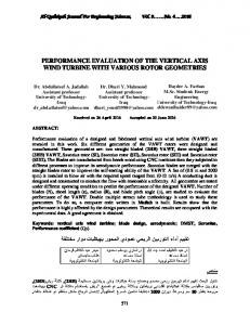
II. CLASSIFICATION OF WIND TURBINES
It is well known that CO2 emission is the major cause of global warming [2]. Daily life activities can be directly or indirectly corelated to the CO2 equivalent emission [3]. There is no source of power available that is free from CO2 emission. For example, in the case of electricity from a thermal power plant, the coal burning is the cause [4]. However, while using a renewable source of energy like Solar PV panel, wind turbine, hydel power plant, etc, the CO2 equivalent comes in to the picture, in terms of the emission caused during manufacturing processes, for which electricity or fuel burning would be the primary source of energy. Since the CO2 emission is the major cause of global warming, the world economies are driven to formulate and follow some guidelines with respect to the total CO2 created by
Since the beginning, two types of windmills and turbines have been built to use this renewable source: some machines with horizontal axis of rotation (HAWT) and some other with vertical axis (VAWT) [6] [7]. The first type is the most common today, but it is not convenient to use for all the required applications. VAWT design has always been criticized in an inferior context than HAWT, but with some new or improved technologies and decreasing prices for valuable materials, this turbine can have a very important advantage in the actual market [8]. The first aerodynamic VAWT was developed by Georges Darrieus in France and first patented in 1927 [9]. Its principle of operation (Fig. 4) depends on the fact that its blade speed is multiple of the wind speed, resulting in an apparent wind throughout the whole
154
International Journal of Applied Engineering Research, ISSN 0973-4562 Vol. 10 No.57 (2015) © Research India Publications; httpwww.ripublication.comijaer.htm
revolution coming as a head wind with only a limited variation in angle.
technology, we can easily make such big structures, but obviously with a greater price and complexity involve in the construction. Moreover, with HWAT, the gear and dynamo has to install at the axis of rotation, which again a very complex and difficult task and leads to misbalancing and related issues to be addressed [12]. Apart from all this, the direction of wind flow will also a factor in harnessing energy from the wind turbine. For this purpose Yawmechanism is used, which not only adds cost but also complexity to the structure [13]. Owing to the discussed issues, researches and engineers have suggested various solutions for effective use HWAT, but their use in the urban areas is still a concern. For that purpose, concept of VAWT has been introduced, which is a promising alternative for low power generation in urban and low wind speed regions.
Wind Turbines
Vertical Axis Wind Turbine
Darrieus type VAWT
Horizontal Axis Wind Turbine
Savonius type VAWT
Fig. 3: Classification of wind turbines
On the other hand, Savonius VAWT [10] was introduced by Finnish engineer S.J. Savonius in 1922 [9]. In its simplest form, it is essentially two cups or half drums fixed to a central shaft in opposing directions. Each cup or drum catches the wind and so turns the shaft, bringing the opposing cup or drum into the flow of the wind.
(a)
(a)
(b) Fig. 5: (a) Velocity Profile of Wind; (b) Tower height versus Power output
IV. VARIOUS DESIGN STUDIES
(b) Fig. 4: Working principle: (a) Darrius rotor; (b) Savonious rotor
Owing to the potential of VAWT in the commercial field and applicability, studies have been done for the analysis and development of its design. Various researchers are intended to make the VAWT design more efficient and easy to use. For this purpose various designing techniques have been used. Gorelov et al., [14] worked on the efficiency analogy between a flapping wing and Darrieus rotor. They have observed that thrust force is the cause of torque produced in VAWT as compared to lift force in HAWT. Kopeika et al., [15] presented an impulsive method of calculating drag coefficient, power coefficient and lift coefficient. Pope et al., [16] worked out a correlation using Buckingham Pi theorem to calculate power coefficient for a given TRS. Howell et al., [17]developed a computational model for the prediction of power coefficient, provided the fluid flow model should be made with all the cautions taken. Hansen et al., [18] proposed a blade element theory, which is easy to use in
III. NEED FOR VAWT As it is well known that horizontal axis wind turbines are the most popular and efficient way to harness wind energy at offshore and big ground locations, but at the same time in order to harness wind energy in urban areas with buildings or obstructions, the speed of wind is not readily available as in the case of HWAT [11]. As can be seen in Fig. 5(a), the velocity profile of wind blowing at a particular location varies in a parabola shape. This is because of the boundary layer formation in the blowing air. Also, with various obstructions this velocity keeps on decreasing further at low heights. Therefore, HWAT are made very high so as to harness maximum power available in the wind. This can be shown through Fig. 4(b), where power varies with height. No doubt that with the present available
155
International Journal of Applied Engineering Research, ISSN 0973-4562 Vol. 10 No.57 (2015) © Research India Publications; httpwww.ripublication.comijaer.htm
calculating the aerodynamic loading of the blades. It helps in designing and manufacturing of the correct blades according to the condition of operation. Following the same, Biswas et al., [19] and Carne et al., [20] used the dynamic analysis in order to predict the vibratory stresses on the blades. They have suggested the algorithms for calculating the fatigue and probable failure period of the turbine. Koepika et al., [15] represented a vortex method to calculate aerodynamic load and coefficient. It is also applied to calculate the efficiency of the turbine. Li et al., [21] analyzed the fluid mass attachment on the blade using wind tunnel testing. The authors have concluded that mass attachment can reduce the power coefficient, which is in proportion to the wind speed and the mass attached. In past one decade, with the advancement in computational and experimental facilities, several design studies are done, which are discussed in the next sections.
transition from laminar to turbulent takes place much earlier than smooth surface, which helps in getting the flow attached and hence, results into lower drag on the airfoil. It is also observed by the authors that the performance of the turbine has dropped after a tip speed ratio of 2.2, considering the wind speed to be 4.3 m/s. As shown in Fig. 6, the 2-D and 3-D CFD models developed by the authors are deviating in predicting the performance coefficient. On the one hand, 2-D model is over predicting, while on the other hand 3-D model is effective enough to predict the performance of the turbine operation.
B. CFD versus PIV analysis of Savonius VAWT In this study, Dobrev et al., [22] used a rotor of height equivalent to its diameter of 3 m is taken for experimental analysis in a wind tunnel. For numerical study, a 3-D CFD tool was developed, using 3 different approaches, out of which k-ω and Detached Eddy Simulation (DES) model is considered to be the best one in predicting the good agreement results with respect to experiments. For the experimental test, wind turbine is allowed to rotate in the range of 800 rpm to 1000 rpm. The wind flow velocity was taken in the range of 9 m/s to 15 m/s, corresponding to which, the value Re number comes out to be 1,40,000 to 1,70,000. With the numerical approach applied for analysis, it has been observed that the ultimate stress plays a defective role on the blade tip when the rotation speed reaches to a value of 1200 rpm. At these conditions, coefficient of performance is calculated for experimental and numerical models. As summarized in Table-1, value of Cp has first increased from TRS of 0.6 to 0.8 and a further increase in TSR has reduced the value of Cp. While comparing the experimental and numerical results, it is found that DES/k-ω SST model is helpful in capturing the results equivalent to the experimental performance.
A. CFD versus Wind tunnel analysis of Darrieus VAWT Howell et al., [17] studied a combined experimental and computational approach for evaluating the performance of a small scale vertical axis wind turbine (VAWT), while considering the aerodynamics principles. The authors have carried out several wind tunnel tests in order to calculate the overall performance of the turbine. A two- and three-dimensional unsteady computational fluid dynamics (CFD) models are also developed to study the aerodynamics of turbine operation. Wind tunnel performance results are presented for cases of different wind velocity, tip-speed ratio and solidity as well as rotor blade surface finish. It is observed that the performance of the turbine is affected by the surface roughness of its rotor blades. It is shown that the performance of either two or three rotor blades turbine decreases with surface finish for lower wind velocities of 4.3 m/s (Reynolds number below 30,000). It is concluded from this study that for a rough surface,
Table. 1: Cp at different TSR values for different modes of study [22] Cp for TRS=0.6 TRS=0.8 TRS=1.05 Experiment
0.176
0.180
0.167
Simulation, unsteady 2D, k-ω
0.182
0.208
0.207
0.141
0.147
0.139
0.172
0.176
0.149
SST Simulation, unsteady 3D, k-ω SST Simulation, unsteady 3D, DES/kω SST (a)
C. CFD analysis of a Novel VAWT Rotor In this work, McTavish et al., [23] presented a novel method of arranging the cups in a stacked manner as given in Fig. 7(a). The cups are designed in such a way that the torque experienced by them can be increased. It uses a combined effect of both drag and o thrust forces. The stacked rotors are given offset of 60 about the vertical axis. A steady state 2-D and rotating 3-D simulation model was developed, in order to capture the performance of the design using aerodynamics principle. The turbulence models used for the simulations are k-ε and RNG. (b) Fig. 6: Cp V/s tip speed ratio for (a) V = 4.31 m/s and (b) V = 5.07 m/s [17]
156
International Journal of Applied Engineering Research, ISSN 0973-4562 Vol. 10 No.57 (2015) © Research India Publications; httpwww.ripublication.comijaer.htm
(a)
Fig. 8: 1/3 scale prototype [24] Table.2: Results Comparison [24]
(b) Fig. 7: (a) Rotar arrangement and geometry; (b) effect of multiple stages on torque coefficient [23]
It is observed from the results obtained that the total torque coefficient over one full revolution is 0.155. Variation in static torque coefficient can be minimized with the increase of number of stages, as seen in Fig. 7(b). It is also observed that the average dynamic torque produced decays rapidly with the increase in tip speed ratio. Hence, for future development of this kind of rotor, a significant work is required to enhance the design of inner and outer wall of the rotor, which causes the stagnation of flow with increase in tip speed ratio.
University Research
Type of Transmission
Wind Velocity (m/s)
Power (W)
Cost (US$)
Wollogong
Gear
25
700
820
Griffith
Gear
20
550
673
Present
Belt and Pulley
6
167
253
E. Three-Bladed Combined Darrieus-Savonius Rotor In this study, Sharma et al., [25] presented a combination of Savonius and Darrieus rotor. As can be seen in Fig. 9(a), Darrieus rotor is on the top, while Savonius is on the bottom, with each of vertical length 10 cm. The number of blades used for both kind of rotors is 3. For Savoniuos type rotor, an overlap arrangement is made. Overlap is the distance of the inner edge of the blade from the axis of rotation assuming the arc is carried to the full semicircle as shown in Fig. 9(b). This overlapping is applied using washers and knurled surface, which helps in changing the overlap from a minimum value of 9.3% to 18.3%. Changing the value of overlap, coefficient of power is calculated, which is shown in the form of a plot in Fig. 10. It is found that value of C p is more for an overlap value of either 16.8% or 18.3%. It is found for the combination of rotors, the performance is better than any of the individual rotors.
rd
D. 1/3 Scale VAWT This research by Hossain et al., [24] explains the electrical power production in Malaysia by the measurement of wind velocity flowing over the wind turbine. In order to predict the performance of an H-type rotor, a 1/3 scale model was developed and performance tests were carried out on this prototype. This prototype is a combination of drag and lift type of rotors as shown in Fig. 8. It is well known that the power produced by the turbine is dependent on the wind power and the transmission system. The transmission system can be of two types: Gear type and RopeBelt type. In this study both wind power and belt power transmission system has been considered. A set of blade and drag devices have been designed for the 1/3 scaled wind turbine at the Thermal Laboratory of Faculty of Engineering, University Industry Selangor (UNISEL). Test has been carried out on the wind turbine with the different wind velocities of 5.89 m/s, 6.08 m/s and 7.02 m/s. From the experiment, the maximum wind power has been calculated as 132.19 W, 145.40 W and 223.80 W as summarized in Table-2. It is also stated that the system is capable to produce 567.33 W, when the wind velocity increases to 20 m/s and 709 W, when the wind velocity increases to 25 m/s.
(a) (b) Fig. 9: (a) Three bladed combined VAWT; (b) Geomery details [25]
157
International Journal of Applied Engineering Research, ISSN 0973-4562 Vol. 10 No.57 (2015) © Research India Publications; httpwww.ripublication.comijaer.htm
V. MATERIAL SELECTION Utilizing the wind power is a costlier affair in terms of fabrication of wind turbines. But with the recent development in research on performance of wind turbines, material selection attracts the concentration of the researchers. Efforts are being made through various studies and a proper material selection criteria has been suggested for different application scenarios [27]. Babu et al., [28] suggested a Multiple Attribute Decision Making (MADM) approach for the section of suitable material for the turbine blades fabrication. Through this work, the authors have analyzed the various design parameter like distortion, stress, etc. for different blade angles, using a numerical study. Based on the results so observed, they have concluded to use carbon fibers as the best material for the operational conditions taken under consideration. P.S. Veers [29] presented a model for estimation of fatigue life of the material used in the turbine. This model depends upon the accurate assessment of the loading and material fatigue durability. It has been concluded through this work that using this design equation, designers can efficiently predicts the probability of failure which can prevent the further loss. Chinchilla et al., [30] suggested the need of research in the field of new advance material for the development of low cost and light weighted VAWT. Various materials that can be used in the basis of their mechanical properties is listed in Table. 3. It can be seen in the table that the use of fibers and their reinforcement with other materials are of good mechanical and physical properties with low density, which makes them a suitable choice for fabrication of VAWT.
Fig. 10: Cp V/s TSR for different values of Overlap [25]
F. Resistance type VAWT for Buildings Generation of wind power in the urban areas is a field of interest of the time, but due to installation problem and technical barriers, there is a need of modification in the use of inherited methods. It can be achieved by deploying some modification to the existing and oldest known form of wind energy convertor, the Sistan type wind mill [ref]. Muller et al., [26] suggested some modifications through this work in Sistan wind mill. The authors have analyzed and tested the turbine with a top disc and increased number of blades. They have concluded that there is an increase of more than 30% in the turbine efficiency with the addition of the top plate, which in turns helps in its installation over the building as shown in Fig. 11(a). With the increase of number of blades from 4 to 6, there can be further increment of 6-7% in the efficiency. For the optimal conditions of testing, the characteristic curves are shown in Fig. 12.
Table. 3: Various material used for rotor design Material Properties Wood
Low density
Steel
Higher inertia; corrosion and oxidation resistance
Aluminum
Lightweight and low tensile strength Fibers and Matrix High strength with materials moderate stiffness and (polyesters, vinyl density esters, epoxies, glass fibers etc.) Carbon fibers High stiffness, high strength, lightweight and low density Aramid fibers High specific tensile strength, excellent environmental and thermal stability, static and dynamic fatigue resistance, and impact resistance
Fig. 11: (a) Geometrical details of Sistan tubine; (b) application in building [26]
Remarks Low stiffness limits elasticity Abandoned because if high weight and low fatigue level Weaker and less stiffer than steel Used as glass reinforced products
Useful for large rotor blades Can be used as Aramid-reinforced thermoplastic composites with excellent wear resistance
VI. CONCLUSIONS In this study a review of various experimental and simulation research is done. From the literature review, it can be concluded that VAWTs are an important area of future research in order to meet the energy requirements. Present trend of studies is leaned towards the combination of Darrieus-Savonius rotor, instead of
Fig. 12: Characteristic curves for the proposed model (a) Power output; (b) Efficiancy [26]
158
International Journal of Applied Engineering Research, ISSN 0973-4562 Vol. 10 No.57 (2015) © Research India Publications; httpwww.ripublication.comijaer.htm [12] B. C. O’Kelly and M. Arshad, “Offshore wind-turbine structures: a using them individually. Use of canted blade geometry is also a review,” Proc. ICE - Energy, vol. 166, pp. 139–152, 2013. promising and emerging area of research, though much work is [13] R. Mittal, K. S. Sandhu, and D. K. Jain, “An Overview of Some
not done in this field till now. The main problem with the use of VAWT is that they are not economical as compared to the power delivered by them. Moreover, they cannot be used for commercial purpose. But for small scale power requirement, they are the best alternatives available. Another problem which is of major concern is the self-starting of the turbine. Mostly, cup type VAWT are not self-starting, so they need an initial impulse to get started. For the same H-rotor and its combination with the drum type VAWT is the solution available.
Important Issues Related to Wind Energy Conversion System (WECS),” Int. J. Environ. Sci. Dev., vol. 1, no. 4, pp. 351–363, 2010.
[14] [15] [16]
[17]
For future course of action, the expected area of research is the concern of making VAWT more efficient and economical. For this purpose, major work is required to be done in terms of material selection of the turbine. In many of the cases, Al is the most widely used material, but there are problem with its machining and manufacturing, which makes the whole process a bit expensive. Some researchers are working in this field and came up with alternative materials like Wood with plastic covering or Fiberglass composites or fiber reinforced plastics instead of Al. Although this field is quite immature, therefore a significant amount of work is expected in order to increase the efficiency and acceptability of VAWT.
[18]
[19]
[20]
[21]
[22]
REFERENCES: [1] [2]
[3] [4]
[5] [6] [7] [8] [9]
[10] [11]
International Energy Agency, “Technology roadmap - Wind energy,” p. 58, 2013. K. Gurney, D. Mendoza, Y. Zhou, M. Fisher, C. Miller, S. Geethakumar, and S. De La Rue Dy Can, “High Resolution fossil fuel combustion emission fluxes for the United States,” Enviromental Sci. Technolofy, vol. Accepted, 2009. R. Lal, “carbon emission from farm operations,” Environ. Int., vol. 30, pp. 981–990, 2004. K. Caldeira, A. K. Jain, and M. I. Hoffert, “Climate sensitivity uncertinity and the Need for Energy Without CO2 Emission,” Science (80-. )., vol. 299, no. March, pp. 2052–2054, 2003. T. Conference, “The Kyoto Protocol: Co2, Ch4 and climate implications,” vol. 25, no. 13, pp. 2285–2288, 2010. “Trends, prspects and R&D directions of the global wind energy sector,” Lab soft energy Appl. Environ. Prot., pp. 1–9, 2013. D. G. Shepherd, “Historical development of the windmill.” 1990. P. N. Shankar, “Development of vertical axis wind turbines,” Sadhana, vol. 2, no. March, pp. 49–66, 1979. M. M. Aslam Bhutta, N. Hayat, A. U. Farooq, Z. Ali, S. R. Jamil, and Z. Hussain, “Vertical axis wind turbine - A review of various configurations and design techniques,” Renew. Sustain. Energy Rev., vol. 16, no. 4, pp. 1926–1939, 2012. I. Ross and A. Altman, “Wind tunnel blockage corrections: Review and application to Savonius vertical-axis wind turbines,” J. Wind Eng. Ind. Aerodyn., vol. 99, pp. 523–538, 2011. E. Sanderson, A. Morrison, E. Taylor, E. Paramasivam, and R. Cme,
[23]
[24]
[25]
[26]
[27]
[28]
[29] [30]
“Study and Development of a Methodology for the Estimation of the
Risk and Harm to Persons from Wind turbines,” pp. 1–86, 2013.
159
D. N. Gorelov, “Analogy between a flapping wing and a wind turbine with a vertical axis of revolution,” J. Appl. Mech. Tech. Phys., vol. 50, pp. 297–299, 2009. T. A. OV Kopeika, “Wind power transforming systems,” J. Math. Sci., vol. 4, p. 104:1631, 2001. T. E. Pope K, Naterer GF, Dincer I, “Power correlation for vertical axis wind turbines with varying geometries,” Int. J. Energy Res., p. 1703, 2010. R. Howell, N. Qin, J. Edwards, and N. Durrani, “Wind tunnel and numerical study of a small vertical axis wind turbine,” Renew. Energy, vol. 35, pp. 412–422, 2010. M. O. L. Hansen, J. N. Sørensen, S. Voutsinas, N. Sørensen, and H. A. Madsen, “State of the art in wind turbine aerodynamics and aeroelasticity,” Prog. Aerosp. Sci., vol. 42, pp. 285–330, 2006. S. Biswas, B. N. Sreedhard, and Y. P. Singh, “Dynamic analysis of a vertical axis wind turbine using a new windload estimation technique,” Comput. Struct., vol. 65, no. 6, pp. 903–916, 1997. T. G. Carne and G. H. James, “The inception of OMA in the development of modal testing technology for wind turbines,” Mech. Syst. Signal Process., vol. 24, pp. 1213–1226, 2010. Y. Li, F. Feng, W. Tain, and Q. He, “Simulation and Wind Tunnel Test on a Straight - Bladed Vertical Axis Wind Turbine,” Res. J. Appl. Sci. Eng. echnology, vol. 5, pp. 2892–2896, 2013. I. Dobrev and F. Massouh, “CFD and PIV investigation of unsteady flow through Savonius wind turbine,” Energy Procedia, vol. 6, pp. 711–720, 2011. S. McTavish, D. Feszty, and T. Sankar, “Steady and rotating computational fluid dynamics simulations of a novel vertical axis wind turbine for small-scale power generation,” Renew. Energy, vol. 41, pp. 171–179, 2012. A. Hossain, a. K. M. P. Iqbal, A. Rahman, M. Arifin, and M. Mazian,
“Design and development of A 1/3 scale vertical axis wind turbine for electrical power generation,” J. Urban Environ. Eng., vol. 1, pp. 53–60, 2007. K. K. Sharma, a Biswas, and R. Gupta, “Performance Measurement of a Three-Bladed Combined Darrieus-Savonius Rotor,” vol. 3, no. 4, 2013. G. Müller, M. F. Jentsch, and E. Stoddart, “Vertical axis resistance type wind turbines for use in buildings,” Renew. Energy, vol. 34, pp. 1407–1412, 2009. A. Chehouri, R. Younes, A. Ilinca, and J. Perron, “Review of performance optimization techniques applied to wind turbines,” Appl. Energy, vol. 142, pp. 361–388, 2015. K. S. Babu, M. S. Reddy, N. V. S. Raju, and N. D. Rao, “The Material Selection for Typical Wind Turbine Blades Using a MADM
Approach & Analysis of Blades,” 18th Int. Conf. Mult. Criteria Decis. Mak., pp. 1–12, 2006. P. S. VEERS, Fatigue loadiong of wind turines. Woodhead Publishing Limited, 2011, pp. 130–158. B. R. Chinchilla, S. Guccione, and J. Tillman, “Wind Power Technologies : A Need for Research and Development in Improving A Need for Research Characteristics,” J. Ind. Technol., vol. 27, no. 1, pp. 1–6, 2011.