It seems that apart from the re-arrangement discussed so far, it is necessary to ..... input: the user may double-click on it to start playing the movie, or click on it to ...
Dialogue modelling in the framework of an interactor model Panos Markopoulos, Jon Rowson and Peter Johnson Dpt. of Computer Science Queen Mary and Westfield College University of London Abstract This paper discusses a formal interactor model called ADC as an architectural construct for modelling human computer interface software. Some intuitions related to the model introduced in [1] are approached more formally. The present exposition focuses upon the specification of one component of the model, called the controller unit, which provides the scope for the dialogue representation. The decomposition of interactors is discussed and exemplified through some extracts from a case study. Decomposition and its opposite the synthesis of interactors [2] are specification transformations that are essential for the use of interactors in the design and development of user interface software.
Keywords Interactors, formal specification, graphical interaction, interactive dialogue, LOTOS, correctness preserving transformation, decomposition, refinement.
Introduction Interactor models are increasingly popular abstractions for modelling interactive systems. Duke et. al. [3] define interactors as ‘components in the description of an interactive system that encapsulate a state, the events that manipulate the state, and the means by which the state is made perceivable to the users of the system...’. They can be used analytically for modelling properties of interactive systems but also as building blocks in the specification of interface software. The ADC interactor model discussed hereby was introduced in [1] as a variation of the interactor model of [4]. It is named after its main components the abstraction, the display and the controller. ADC is characterised by the specification in distinct modules of the data operations and the temporal ordering of the behaviour of the interactor. The advantages sought with this modularity pertain to the derived engineering properties. In [1] a scrolling list was modelled as the composition of the specifications of a scrollable list of elements and a scroll-bar interactor. It was observed that the composition expression could itself be written in the form of the ADC model. It was suggested that this was a general property for compositions of ADC interactors that was built into the model. This rewriting is more rigorously discussed as a transformation of interactor specifications called synthesis in [2]. Synthesis serves the bottom up construction of higher level components from simpler constituents. Top down development requires the refinement of interactor specifications. One form of refinement is the decomposition of interactor specifications discussed below. The concept of the abstract view of an ADC interactor is introduced. An abstract view of an ADC interactor specification concerns mostly compound expressions where some of the internal organisation of the composition is abstracted away from. The presentation in later sections aims to discuss the meaning of abstract views, their decompositions and to exemplify their use. Examples are taken from a case study in the specification of a graphical interface to a multimedia application, using the ADC model, albeit with an imaginary sequence of design steps. The focus of this paper is the issue of dialogue representation in the context of the ADC model. Dialogue modelling and notations for the specification of the dialogue structure supported by an interface are traditional concerns of research in human computer interaction [5]. An architectural model like the ADC interactor provides a framework that defines the scope of the dialogue representation. Further it facilitates the verification of dialogue properties in a modular fashion. The first section introduces the ADC model briefly. The full definition of the model found in [1] is not repeated as this presentation focuses upon the specification in LOTOS of the controller unit, that contains the dialogue specification. Some of the properties of the ADC model, the concept of abstract views and their manipulations are discussed in
Dialogue modelling in the framework of an interactor models
section 2. Section 3 discusses the scope of dialogue modelling in the ADC model. In section 4, these ideas are exemplified in the context of the specification of a simple interactive application.
1. A brief introduction to the ADC model
abstraction side aInpData
aInp
aOutData
aOut start suspend
Abstraction and Display Unit
Controller Unit
resume restart abort
dOut
dInp
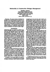
Similar to Paternó [4], d dOutData dInpData interactors are seen as basic communication entities that cooperate with each other in display side order to manage the dialogue between a user and Figure 1. The internal structure of an interactor. an application. Interactors are modelled as LOTOS processes which can communicate with each other and possibly with the user or the application. Interactions take place over the gates of the process, they have no duration but may have a structure that models the transfer of data into or out of the interactor. The interface can be modelled as a graph whose nodes are the interactors and whose edges correspond to connections between them over a pair of gates. Interactors may also be connected to agents representing the application and the user. Unlike LOTOS processes the communication of information is directed. When both the display state and the abstraction state are used to interpret received input, this is considered to be arriving at the display side. Intuitively, this corresponds to user input that the interactor needs to de-reference with respect to the current display. In practice this is the only difference between input arriving to one side or the other. Choosing which side an interactor gate belongs to does not depend on what it connects to but on how the information received should be interpreted. Note that the interpretation of input based on the display contents characterises graphical interaction. The ADC model distinguishes three aspects of the interactor description which are described in distinct modules: (a) the data held by the interactor and the operations it applies to the data described in the AD (abstraction - display) data type. (b) a process holding as its local parameters (information hiding) the abstraction and the display states of the interactor. This process called the Abstraction and Display Unit (ADU) links the data operations to the events that cause them. (c) the temporal ordering of its behaviour described in the Controller Unit (CU). The ADC interactor is defined as a LOTOS process that is formed by the parallel composition the ADU and the CU. ADC[G c ∪Gio ](State) = ADU[Gio ](State) |[Gio ]| CU[Gc ∪Gio ] where State stands for the state parameters of the ADU, pertaining to the abstraction and the display state of the interactor. The set of input and output gates G io contains all the gates of the ADU. An event occurrence on such a gate may update the abstraction and display states of the ADU and may output their values. G io is partitioned into subsets, distinguished by the direction of communication (input or output) and the side of the interactor (abstraction or display). Event occurrences over a gate invoke different operations for each of these subsets. The operations applied by the ADU are defined by the data type AD. For a particular type of interactor a corresponding data type AD has to be defined. The signature of these data types follows the general form introduced in [1]. This is not repeated as the present discussion focuses on the specification of the CU. However it is worth noting that the gates in the set Gio are typed, according to their purpose. In figure 1, it can be seen that on the display side input gates may receive data of sort dInpData and output gates will offer data of sort dOutData. On the application side input gates may receive data of sort aInpData and output gates may offer data of sort aOutData. Finally, events on the gates in G c do not have any effect on the abstraction and display state and carry no data. They are used only in the specification of the controller behaviour and are indicated in figure 1 as single lines to gates of the controller unit. Characteristically, the ADU is neutral with respect to the temporal ordering of its interactions: at all times it offers events on all its gates. The temporal ordering of these events is determined by the CU with which the ADU synchronises over all of its gates (figure 1). The CU maintains no state, in terms of values of state parameters, but
DSV-IS’96 Informal Proceeding
simply encodes an ordering of events on its gates. It also encodes some standard behaviours built in the ADC interactor structure. The interactor is defined with gate sets that have the effect of starting, suspending, resuming, restarting and aborting the operation of the interactor. For short these standard behaviours and the corresponding gates are referred to as SSRRA behaviours (res. gates). They are offered to the specifier-user of the model in a parameterised form, that requires only instantiation of the gate identifiers and appropriately connecting the gates to other interactors. Interactors are represented in diagrams as barrel shaped nodes with the top and bottom arches dedicated to connections to the abstraction and display side respectively. The vertical sides are dedicated to controller connections, i.e. gates of the controller process that do not belong to the ADU. A LOTOS process definition below shows the overall structure of the CU component. For simplicity, assume that gate sets are atomic, thus there is only one start event, only one resume event etc. which are named accordingly. Similarly let Gio = {dInp, dOut, aInp, aOut} whose purpose is respectively: to receive input at the display side, to output the display state and to receive input and output data at the abstraction side. It has already been mentioned that events on these are typed, in accordance to the typing of the ADU. However, the CU does not impose any selection predicate on the values offered and does not record this information in some local state component. Other than the typing information on its gates, which is necessary for the synchronisation with the ADU, the CU ignores the data values associated with events. The standard structure of the CU aims to support the standard SSRRA behaviours, while dialogue particular to the interactor is encoded in the constraints component (CC). The CC specifies separately the temporal ordering of events on the input and output gates that are common with the ADU and gates dedicated for dialogue control. The latter have no effect on the values of the data held by the ADU, so they do not belong in the alphabet of this process, but may easily alter the ‘dialogue state’. Let Gdialogue ={d} in the following discussion; in practice there could be zero or more such events. CU[start, restart, suspend, resume, abort, d, dInp, dOut, aInp, aOut] := start; RUN [restart, suspend, resume, abort, d, dInp, dOut, aInp, aOut] RUN[restart, suspend, resume, abort, d, dInp, dOut, aInp, aOut] := (CC[d, dInp, dOut, aInp, aOut] |[d, dInp, dOut, aInp, aOut]| SUSP_RESUM [suspend, resume, d, dInp, dOut, aInp, aOut]) [> INTERRUPT[restart, suspend, resume, abort, d, dInp, dOut, aInp, aOut] SUSP_RESUM [suspend, resume, d, dInp, dOut, aInp, aOut] := ANYORDER [d, dInp, dOut, aInp, aOut] [> suspend; resume; SUSP_RESUM [suspend, resume, d, dInp, dOut, aInp, aOut] ANYORDER [d, dInp, dOut, aInp, aOut] := d; ANYORDER [d, dInp, dOut, aInp, aOut] [] dInp?X:dInpData; ANYORDER [d, dInp, dOut, aInp, aOut] [] dOut?X:dOutData; ANYORDER [d, dInp, dOut, aInp, aOut] [] aInp?X:aInpData; ANYORDER [d, dInp, dOut, aInp, aOut] [] aOut?X:aOutData; ANYORDER [d, dInp, dOut, aInp, aOut] CC[d, dInp, dOut, aInp, aOut] := d; dInp?X:dInpData; dOut?X:dOutData;aInp?X:aInpData; aOut?X:aOutData; CC[d, dInp, dOut, aInp, aOut] INTERRUPT[restart, suspend, resume, abort, d, dInp, dOut, aInp, aOut] := restart; RUN[restart, suspend, resume, abort, d, dInp, dOut, aInp, aOut] [] abort; EXIT Process SUSP_RESUM describes the suspension behaviour of the interactor: it halts with the suspend event and resumes where it was with a resume; the rest of the time it allows events in Gdialogue ∪ G io to happen in any order. Event abort terminates the operation of the interactor and the process exits. In the contrived case above process CC imposes a strict sequence of events on its gates, that corresponds to the clockwise direction on figure 1. A restart event has the effect of restarting the constraints process, so that the local dialogue returns to its initial state i.e. the one that follows a start event. It takes a complex process definition to support the standard control behaviours. Here, they are supported by syntactic extensions only. The same result could be achieved by simple extensions to the semantics of LOTOS, but then existing
Dialogue modelling in the framework of an interactor models
tool support would not be usable. The parameterised description of standard behaviours is an attractive feature of the model, as their definition becomes a simple task for the specifier-user of the model. There is a similarity in the naming and the purpose of the components of the ADC model and the informal conceptual software architecture PAC[14] which also constructs the interface software as a composition of elementary units. However the two are quite distinct. In the PAC model the presentation and the abstraction are held by distinct agents as opposed to been managed by a single ADU. In the ADC scheme, a formal specification template has been defined for the AD data type that outlines the relationship between abstraction and display. In PAC it is the responsibility of the controller component to maintain a correspondence between the two; the CU of the ADC model specifies only the temporal structure of interactions with the environment. The ADU can be thought of as a passive transducer of information converting the information from a user perceivable represetnation to an internal application oriented representation and vice versa. This is the designated role of the communication component in the model proposed by Kovacevic [15]. Kovacevic also introduces a control component similar to the CU which specifies the dialogue structure. The model of Kovacevic adopts a macroscopic view of the interface software. The two components already mentioned plus a buffering component are put together to form the interface software in its totality. In terms of the ADC interactor model this would amount to modelling the whole interface as a single interactor.
Example Consider the resize box for a simple window based application like for example the one indicated in figure 5. It is always displayed as an icon, which is standard for Macintosh applications. Its position on the screen may be modified if the user drags it. The other elements of the display in figure 5 are resized or repositioned when the user stops dragging the resize box. If this resize box is modelled as an ADC interactor, then its abstraction will be some screen coordinate that is passed on to the other interactors comprising the interface and is interpreted by them accordingly. Its display state is simply its position on the screen, and possibly some default value denoting the resize box icon. However, when this icon is dragged it provides some feedback which is the outline of the window. Operation echoMove represents this intermediate output. The ADU component for this resize box will have the form below (data type specifications are omitted for brevity): RESIZE_ADU[press, move, release, dOut, aOut](a:rct, dc,ds:icon) : noexit := dOut!dc; RESIZE_ADU [...] (a, dc, dc) [] press?x:pnt; RESIZE_ADU [...] (inpPr(ds,a,x), echoPr(ds,a,x), ds) [] move?x:pnt; RESIZE_ADU [...] (inpMov(ds,a,x),echoMove(ds,a,x), ds) [] release?x:pnt; RESIZE_ADU [...] (inpRel(ds,a,x), echoRel(ds,a,x), ds) [] aOut!result(a); RESIZE_ADU [...] (a, dc, ds) The dialogue structure described in the CC follows easily from the description above. After a press or a move the intermediate feedback is shown, while the other interactors receive the new position information only after a release event, through gate aOut. A constraint is added, described in process INP_CONTROL, that a press is followed by a sequence of zero or more moves and finally terminated with a release. RESIZE_CC [press, move, release, dOut, aOut]:= SEQ[press, move, release, dOut, aOut] |[press, move, release]| INP_CONTROL[press, move, release] where SEQ [press, move, release, dOut, aOut a]:= press?x:pnt; dOut?x:icon; SEQ [...] [] move?x:pnt; dOut?x:icon; SEQ [...] [] release?x:pnt; dOut?x:icon; aOut?x:rct; SEQ [...] [] dOut?x:rct; SEQ [...] INP_CONTROL[press, move, release]:= press?x:pnt; (REPEAT[move] [> release?x:pnt; INP_CONTROL[...])
2. Design transformations of ADC interactor specifications This section is a brief account of some of the engineering properties of the ADC model. The presentation consists in a set of propositions without their proofs. The focus of this section is not on establishing the truth of these properties but to outline some essential manipulations of ADC specifications that correspond to intuitive design steps. In particular
DSV-IS’96 Informal Proceeding
ADU ADU
A
CU A
|[G]|
ADU B B
CU B
CU
A
G1
B
G
ADU A
CU B
Figure 2. The synthesis of two interactors into one the propositions try to provide a theoretical underpinning of user interface dialogue design in the context of the ADC model.
2.1 Compositionality and the synthesis transformation Compositionality is an important attribute of ADC interactors. It pertains to the synthesis of higher level interactors from lower level ones. Compositionality is discussed extensively in [2] where the proposition below is proven, in a more general form, as the correctness preservation requirement in a rewriting transformation of specifications of ADC interactors called the synthesis transformation. Synthesis rewrites a LOTOS composition expression that involves two ADC interactors into a strongly equivalent ADC interactor specification. In the remaining of this paper only the synchronous composition of interactors is discussed. Proposition 1. A composition of two ADC interactor specifications over a gate set G can be rewritten as a strongly equivalent ADC interactor, called the compound form. The CU of the compound form is the parallel composition of the two component CUs over the gate set G and its ADU is formed by the parallel composition of the two component ADUs over a gate set G1 = G io A ∩ G io B ∩ G - ((G io A ∩ G c B) ∪ (Gio B ∩ G c A)) where the gate sets for interactors ADC A and ADCB are indicated accordingly (figure 2). The transformation termed synthesis, preserves strong observational equivalence, denoted by ~. A B A (ADUA | [ Gio ] | CUA ) | [G] | (ADUB | [ Gio ] | CUB ) ~ (ADUA | [G1 ] | ADUB ) | [ Gio ∪ GBio ] | (CUA | [G] | CUB )
The right hand side of the above equivalence is a behaviour expression that can be itself considered to be an ADC interactor. The parallel composition of the two ADUs can be shown to be itself an ADU [2]. This transformation is a form of a distribution of the synchronisation operator with the proviso that the ADUs synchronise not on the gate set G itself but to its subset G 1 that excludes gates that might reflect cross synchronisation of the ADU with the CU of the other interactors.
2.2 Abstract Views of Interactors Hiding may be applied to an interactor, or to a group of interactors to abstract from internal detail. In the discussion that follows, the term abstract view refers to an interactor some of whose gates are hidden. Abstract views are illustrated as black boxes enclosing the interactors-barrels. In specifying interface architectures abstract views are as interesting as interactors themselves. Composite interactors need to be examined without reference to their internal organisation and abstract views are useful so as to hide gates connecting their components. The synthesis transformation applies to abstract views, as well as simple interactors. It might involve an abstract view and an interactor, or two abstract views. Proposition 2. A synchronous composition of the abstract views of two ADC interactors, can be rewritten in an observationally equivalent form, as the abstract view of the synthesis of the two interactors (figure 3). The only condition for this is that the gate labels hidden by each abstract view do not overlap with the gate labels of the other. A ∀ gA , gB | gA ∉ (GBio ∪ GBc ) ∪ G ∧ gB ∉ (GA io ∪ Gc ) ∪ G • A (hide gA in (ADUA | [ Gio ] | CUA )) | [G] | (hide gA in(ADUB | [ GBio ] | CUB )) ~ A hide [gA , gB ] in ((ADUA | [G1 ] | ADUB ) | [ Gio ∪ GBio ] | (CUA | [G] | CUB ))
Proof. By application of the graphical composition theorem with hiding [6].
Dialogue modelling in the framework of an interactor models
In the special case where g B∩(Gc B∪Gio B ) = ∅, the above describes the composition of an abstract view with an interactor. If the same holds for gA then the above reduces to the equivalence of proposition 1.
2.3 Decomposition The synthesis transformation and its variation for abstract views illustrated in figure 3 may be considered in the reverse direction, in which case they describe the decomposition of a compound interactor. A LOTOS behaviour expression describing a compound interactor or its abstract view is rewritten as a composition expression involving smaller scale components. This could serve a process of stepwise refinement of a higher level abstract specification to a detailed architectural model of the interface. Just as the synthesis transformation it involves a rearrangement of the components of a synchronous composition expression. This rearrangement of the component processes is only possible if the behaviour expression has the structure of the compound form: a pair-wise composition of two ADU and two CU components. In general an ADC specification will not have this form. It seems that apart from the re-arrangement discussed so far, it is necessary to consider the decomposition of an interactor specification that involves the decomposition of its components as well. A special case is examined below where the interactor is written in the constraint oriented style. This refers to the specification of the CC, the only component process with a variable specification style. The constraint oriented style fits better the initial stages of the design, where requirements are specified without reference to the architecture of the software designed [7]. It should be possible to extend this transformation to other structures of the CC, but algorithms to do so are quite complicated and restricted (cf. [9] for the decomposition of finite basic LOTOS processes). As mentioned previously the CC component describes the custom dialogue properties of the interactor modelled. In the constraint oriented style of specification, each logical constraint on the dialogue of the interactor is expressed as a behaviour expression. These expressions are composed by means of parallel operators. Unsynchronised composition (interleaving) combines the logical constraints in a disjunction. Synchronised composition produces a conjunction of the logical constraints expressed. Proposition 3. Consider an interactor whose CU has the standard structure of section 2: CU := start; RUN RUN := (CC|[G dialogue ∪ Gio ]|SUSP_RESUME) [> INTERRUPT Let CC be written in the constraint oriented style, as the parallel composition of constraints CCA , CC B, CC AB, respectively describing temporal ordering constraints on gate sets A, B and AB⊆A∪B. CC := CCA[A] |[G]| CCB[B] |[AB]| CCAB[AB] where AB⊆A∪B= Gdialogue ∪ Gio and G ⊆ G dialogue ∪ Gio Then the CU can be rewritten in the strongly equivalent form CU A[SSRRA∪A] |[ SSRRA∪G]| CU B[SSRRA∪B] |[SSRRA∪AB ]| CUAB[SSRRA∪AB] where CU x := start; RUNx RUNx := (CCx|[x]|SUSP_RESUMEx)[> INTERRUPT x, x∈{A, B, AB} where processes RUN x, SUSP_RESUMx and INTERRUPTx are defined as in section 1. Corollary. Provided that the CU is written in the constraint based style it is always possible to rewrite an ADC interactor as a synchronous composition of simpler interactors, that synchronise at least on the SSRRA gates. The composition expression relating the ADC interactors is isomorphic to the parallel composition expression of the original CC component.
ADUA CUA ADU A CUA
|[G]| ADU B CUB
G
G
ADUB CUB
ADUA CUA ADU A CU A
|[G]|
ADU B CUB
G
G
ADUB CUB
Figure 3. Synthesis of an abstract view from two abstract views, or an abstract view and an interactor.
DSV-IS’96 Informal Proceeding
Consider an ADC interactor whose CC is written in the constraint based style: CC[A ∪B] = CC A[A] |[G]| CC B[B] |[A ∪B]| CCAB[AB] This can be rewritten as the composition of three interactors ADCx= ADU x[G io x]|CUx, x∈{A,B} and ADC AB= CUAB, where CU X is defined as in proposition 3 and the ADU is rewritten as ADU[Gio ] = ADU A[G io A] |[G1]| ADUB[G io B], where Gio x= x ∩G io By application of proposition 1, the ADC can be decomposed as: ADC = ADC A[SSRRA∪GA] |[ SSRRA ∪G]| ADCB[SSRRA∪GB] |[ SSRRA ∪GA∪GB]| CU AB[SSRRA∪GA∪GB] Individual constraints that are composed in the CC concern subsets of its gates. The most modular decompositions result when there are no constraints across the two subsets of gates as in CC AB above. This also holds in the more extreme case where there are no constraints established on the temporal ordering of events on the interactor considered, e.g. because it is still an early stage of the design activity. In both these cases the third component CU AB may be omitted, and the interactor is decomposed into components ADC A and ADC B only. Several types of decomposition have been discussed. They can be used in a stepwise design process that starts from a high level view of the designed interface as a single interactor, or a single abstract view, and proceeds to create an architectural model that implements it and that also defines the architecture of the designed system. An imaginary such design trajectory is presented in section 4.
3. Dialogue modelling and the ADC model In the context of human computer interaction the term dialogue is conventionally interpreted as the syntactic structure of the interaction between user and computer that determines the temporal ordering of input and output that the interface software supports. The notion of syntax is rooted in linguistic models [5] of interaction that distinguish the lexical, syntactic and semantic levels of abstraction. The barrier between these levels of abstraction is not at all clear cut. Where it is set is affected by the notation used for the specification of the dialogue, the implementation architecture and the personalised specification style adopted by the designer. The distinction of these levels, is not an inherent characteristic of the modelled interaction but a characteristic of the representation scheme chosen and the intended use of the model. In the framework of the ADC interactor the semantics of the interface are modelled as operations on data handled by interactors. The temporal ordering of such interactions is nominally the dialogue. In a specification of an interface based on the ADC model the dialogue will be distributed among the CU components of the interactors involved. However, it is stressed that what is modelled as dialogue in the ADC model is not inherently a property of either the specificand, i.e. the modelled interface or the ADC model itself. What one specifier may choose to encode as dialogue ordering, may be encoded in the semantics of data operations by another. The choice is in fact identical to the choice between specification notations for representing interaction dialogues. For example Palanque and Bastide [8] compare the specification of a small interaction dialogue in three different notations. Their comparison shows how the same elements of dialogue may be encoded in either of an event based formalism, a state oriented formalism or a Petri Net. The barrier with the lexical level interaction is also fuzzy. In the case of the ADC model there is no distinct lexical level. It is defined implicitly by the lowest level of abstraction events considered. For example if mouse input is considered as the lowest level input event, then this is where the barrier is put, and similarly for output events. Within the framework of the ADC model, dialogue design consists partly in the instantiation of the standard (SSRRA) behaviours and partly in designing the temporal ordering for the remaining of interactions. This latter set of behaviours is defined entirely in the constraints component of the CU. These intuitions are formalised in the following paragraph.
A formal treatment of dialogue modelling From the understanding of what is dialogue it follows that the data values associated with events may be ignored when discussing dialogue properties. This may be achieved in practice by a transformation from Full LOTOS to Basic LOTOS. One such transformation, the naive transformation, creates a basic LOTOS specification that offers an event defined by a gate identifier only for each event modelled by the full LOTOS specification. A rigorous definition of the relationship between the two specifications can be found in [9]. The intuition of what is dialogue can now be rephrased as below.
Dialogue modelling in the framework of an interactor models
Definition. The dialogue of an ADC specification is described by P(ADC) where P is the naive transformation from full LOTOS to basic LOTOS that simply ignores the whole of the data component of a LOTOS action specification. The following proposition can be shown on the basis of properties of the naive transformation and of the ADC structure. Proposition 4. P(ADC), which represents the specification of the interaction dialogue in an ADC interactor, is strongly observationally equivalent to P(CU). P(ADC) ~ P(CU) Clearly, to verify dialogue properties of the specification it will be enough that they are verified for the basic LOTOS transformation of the CU. This is useful to overcome the practical difficulty in verifying properties of full LOTOS specifications and also of managing complex behaviour expressions.
4. Exposition of a specification in a top down fashion Simple Player™ is an application program for the Macintosh computer that provides access to play back and editing facilities of the QuickTime™ system software extension. This section presents some aspects of a reverse engineered specification that was developed as part of a case study [10]. The case study aimed to test the feasibility and practicality of basing the specification of a realistic graphical interface on the ADC interactor model. This section examines how the decomposition of interactors or their abstract views corresponds to simple design steps that lead to an architectural model of the interface software. Only the dialogue specification is discussed below. By proposition 4 this limits the discussion to the formal specification of the controller unit component. An architectural model of the Simple Player™ graphical interface was constructed. It is stressed that this architecture is fictional in the sense that the actual software is not at all structured according to the ADC model. The scope of the specification includes only the graphical interaction, since this is the intended domain of application of the ADC interactor model. Only the application functionality accessed through graphical interaction is relevant, and the only physical input device modelled is the mouse with the addition of the keyboard modifiers to mouse input. The subset of functionality modelled is referred to as the functional core. The exposition of the case study is top down: it follows an imaginary trajectory from the most abstract as a single abstract view, to its decomposition to a network of interactors that implement the abstract specification. In this case all interactors start, restart, suspend and abort as one, so the design of the dialogue for each interactor need only be concerned with the constraints component while all the interactors are assumed to synchronise over their SSRRA gates. By specifying the dialogue in the constraints components for each of the interactors identified in this process a refinement of the specification results. Further refinement results with the specification of the associated data types. The data type specifications are not in the scope of this exposition; the reader is referred to [10] for a full description of the specification. A QuickTime™ movie is modelled as a sequence of frames which can be output as video with sound or stills, and which are indexed according to an integer time coordinate. Selections may be defined on this sequence and attributes of the movie like its display area, and the current volume may be modified. The decision of what to model as the behaviour of the functional core and what as behaviour of the interface is an arbitrary decision that defines the scope of the specification exercise [10]. Below the borderline between the two is described by a list of functions invoked by the interface. It was attempted to follow as much as possible the definitions of the Movie Controller and Movie Toolbox function libraries documented in [11]. The invocation of an application function is modelled as an event on a gate of the top level ADC interactor. The gates and their purpose are the following:
display area
resize box volume control
player bar
play/pause button
selection step backwards and forwards band
thumb showing the current position
Figure 4. Simple Player™ and its components
getVolume video
setVolume
setAllFrames
setMovieBox
gotoEnd
setSelection
gotoStart
gotoTime
start suspend resume restart abort
getTime
pause
out_ok
play
DSV-IS’96 Informal Proceeding
Simple Player Graphical Interaction
display
keyboardModifiers
mouseInput
Figure 5. The level 0 abstract view getMovieVolume, setMovieVolume. The interface reads/modifies the current setting of the volume. getTime/gotoTime . The interface reads/modifies the time coordinate of the current frame. gotoEnd/gotoStart. The current time is set respectively to 0 or to the duration of the movie. out_ok. Models the synchronisation of the functional core with the display. video. Events on this gate represent the output of movie data. play. An action on this gate is associated with an integer value as a parameter which indicates the rate of play. It plays forward for a positive value, backwards for a negative value and pauses for a value zero. pause. The interface makes the application to stop playing the movie. setAllFrames. It sets a Boolean value associated with the movie, that indicates whether all frames should be played or not. If true, all frames will be played even if this means that the required rate of play is not achieved. setSelection. The interface sets the current selection of the movie. This is defined by two integers in between 0 and the duration of the movie. setMovieBox. This action models the invocation of the movie controller function setMovieBox by which the application handles changes to the display region. Consider the whole of the graphical interface modelled as an ADC interactor. On its abstraction side it interacts directly with the functional core and on the display side directly with the user. Neither the user nor the functional core are described below, although in [10] a process modelling the behaviour of the functional core was specified as a boot strapping activity. The interface is assumed to have several hidden internal communications, so it is represented as an abstract view (level 0) where all possible mouse input is grouped under the heading mouseInput and all keyboard modification input under the heading keyboardModifiers. In an initial design stage where the interactors have not yet been decided, these headings are place holders for the gate names that will be filled-in later. Arrows indicate gates where data values are associated with events and simple lines where they do not.
keyboard modifiers
level 1
SSRRA
outVol display mouseInput
getVolume
setMovieBox
setVolume
video
setSelection out_ok setAllFrames
gotoStart gotoEnd
getTime
pause gotoTime
play
Lets assume that the first step in the imaginary design trajectory is the separate description of volume control. Gates specific to volume control are ‘assigned’ to a separate interactor. This is connected to level 1 abstract view (what remains from level 0) by the SSRRA gates and the gate setMovieBox, from where it receives display coordinates. In
volume control
press move release
Figure 6. Decomposition into an interactor and the level 1 abstract view
mouseInput
outSB outTHMB
player bar interactors
mouseInput
setSelection
gotoTime
outPLR iaTHMB
thumb
selection band enable erase send
inpSB
SSRRA
setMovieBox
oaSB
display gates
level 2
iaSB
playerBar
outSB
kyeboard modifiers
getTime
setMovieBox
gotoTime
setSelection
setMovieBox
getTime
gotoTime gotoEnd gotoStart setAllFrames
getTime
play
pause out_ok video
Dialogue modelling in the framework of an interactor models
outTHMB
pressPLR relTHMB moveTHMB
Figure 7. Decomposition to level 2 and player_bar abstract views and the player bar components accordance to proposition 4 the dialogue is sufficiently described by P(CU). Since all interactors will have synchronised SSRRA behaviours, dialogue design need only be concerned with P(CC). The volume control is a slider that pops up with a mouse press and its output informs the user about the current volume setting and allows the user to modify it. It pops down when the user releases the mouse button. The CC is the composition of process SEQ that handles end to end constraints and an input control process identical to the one for the resize box. CC_VOLUME[press, move, release, outVol, setMovieBox, getVolume, setVolume]:= SEQ[press, move, release, outVol, setMovieBox, getVolume, setVolume] |[ press, move, release]| INP_CONTROL[press, move, release] SEQ[press, move, release, outVol, setMovieBox, getVolume, setVolume]:= press; getVolume; outVol; SEQ[...] [] move; outVol; setVolume; SEQ[...] [] release; outVol; SEQ[...] [] setMovieBox; SEQ[...] [] outVol; SEQ[...] The Caesar/Aldebaran [12] model checking tool was used to verify some properties that could be of interest to the designer. For example, it might be required that an instant syntactic feedback, i.e. an event on gate outVol, is offered for all user input. This property was found not to be true for the above specification: the volume interactor asks the application about the current volume, with an event getVolume after each mouse press, and before showing the current volume setting in the form of a pop up slider, with an event outVol . On the contrary it was shown that feedback is always given before new input is given by the user, and that movement of the mouse will instantly trigger a setVolume event etc. In each of these cases, the required property is directly modelled in LOTOS and the observational equivalence between the property and the specification may be shown. This equivalence is shown up to a renaming that maps all user input to a single event in the property specification and a hiding of the events which are irrelevant to the property modelled. Level 1 is decomposed further to an abstract view that represents all interactions with the player bar (figure 7). This could be modelled as a single interactor, but as it turns out it was easier to model as a complex of three interactors and two connectives. This is simply the approach chosen for the specification and does not suggest that this is how the player bar is in fact implemented or that it should necessarily be specified with this configuration. The interactors are the playerBar, the selectionBand and the thumb. Their specification can be found in [10], and their composition to a higher level interactor describing all player bar interactions is discussed extensively in [2]. The dialogue of this compound component is described by a CC which is formed by the composition of the CCs of the parts. CC[...]:= ((CC_PLAYERBAR[inpPLR, oaSB, outPLR, setMovieBox, getTime, gotoTime, setSelection] |[ outPLR]| CC_AND1[outPLR, iaTHMB, iaSB]) |[iaTHMB, inpPLR]| (CC_THUMB[pressPLR, moveTHMB, relTHMB, outTHMB, iaTHMB, oaTHMB] |[oaTHMB]| CC_AND2[oaTHMB, inpPLR, inpSB])) |[inpSB, oaSB, iaSB]|
keyboard modifiers
level 3
iaDSP playDSP pauseDSP RRSSA
setAllFrames
gotoStart
gotoEnd
getTime
level 4
keyboard modifiers
display
click doubleClick
display display
video
gotoTime
out_ok
pause
setMovieBox play
setAllFrames
gotoEnd
gotoStart
gotoTime
getTime
pause
play
DSV-IS’96 Informal Proceeding
display
setMovieBox
resize box
SSRRA
mouseInput
mouse input
outBox
pressBox moveBox releaseBox
Figure 8. Two more decomposition steps that factor out the display and the resize box interactors CC_SB[inpSB, outSB, iaSB, oaSB, erase, enable, send] The model checking tool was used to verify some properties that a designer might wish to verify for this group of interactors. For example, it was verified that mouse input on the thumb effects a gotoTime command, or that an output from the application of a current time value via the gate getTime will result in an update of the display of the thumb on gate outTHMB. The properties that may be inferred by model checking mentioned so far serve to establish the correctness of the interface software. For example, in each occasion it is asked whether an input event on the display side will cause an output event on the application side, whether it has echo etc. There is generally no ‘correct’ answer to these questions nor has there been a fixed set of such questions predefined. It is left upon the interface designer to choose how the interactor should behave. The designer may encode design constraints that could, to her judgement, improve usability. Thus returning to the example discussed the designer might wish to add extra constraints across components e.g. that the output for the selection band and the thumb should be in step, and with the selection band always trailing the thumb. This could be written as a process synchronising with the above expression over gates outSB and outTHMB, and which would be: INSTEP[outTHMB, outSB] := outTHMB; outSB; INSTEP[outTHMB, outSB] The revised constraint component would be defined by CC’[...] := CC|[outTHMB, outSB]| INSTEP[...] By the application of the corollary of proposition 3, the graph on the right side of figure 7 would be amended with an interactor consisting only in a controller unit that could connect to gates outTHMB of thumb and outSB of selectionBand. The output of video and still images is achieved through the display area of the Simple Player which also serves for input: the user may double-click on it to start playing the movie, or click on it to stop playing. It does not maintain an abstraction state so it is illustrated in figure 8 as a half barrel directed towards the display side (downwards). Its specification can also be found in [10].
level 0 volume
level 1 playerBar
selection band
level 2
thumb
display
level 3 resize box
level 4
Figure 9. The levels of decomposition so far, and the resulting interactor nodes.
Dialogue modelling in the framework of an interactor models
The resize box of Simple Player indicated in figure 4 can also be separately modelled by an ADC interactor. It synchronises with level 4 over a gate setMovie box, over which it sends its screen coordinates to the rest of the interactors that appear on the display. The specification for this interactor was outlined as an example in section 2. The decomposition proceeds in this fashion, until a composition expression involving only elementary interactors results. Figure 9 shows the levels of the de-composition considered so far, and the nodes of the resulting composition graph. The example demonstrates the use of the ADC model for the modular decomposition of a specification problem. The actual design of the architecture of the specification accomplished for the purposes of the case study, resembles closely this idealised view, possibly due to the reverse engineering character of the case study. Deviations reflect problems found on the way, e.g. unforeseen dependencies between interactors, or the introduction of logical connectives, as in figure 8. The most interesting aspect of the decomposition is that it results in manageable units whose dialogue and data handling are modelled individually. The decomposition of interactors is most useful when the design introduces dialogue constraints at the higher level of specification. According to proposition 3, constraints are preserved during decomposition in the architectural model produced. Unfortunately the gate sets involved in the specification of the constraints at the top level have to be identified in advance of the architecture design. This is consistent with a top down design method but not necessarily consistent with actual design practice. In the exposition shown previously this issue was concealed by using sets of gate identifiers, e.g. mouse input etc. Such categorisation of gates is also useful in the analytical evaluation of interface properties, that will relate such classes of gates: e.g. input and feedback etc. This observation highlights a limitation of LOTOS as a formal framework for the specification of interactors in that it cannot support the refinement of gate identifiers.
Conclusion Interactor models serve two complementary purposes. One is analytic, for the study of phenomena of interaction and the other is an engineering role for the description of the structure of a designed system. The two roles are not exclusive; an engineering model ought to be an analytic tool for the design, while an analytical model that is used to capture high level requirements, in practice has to be refined to a system design. In [3] two interactor models are compared with respect to these uses. It is concluded that the interactor model of [4] is better geared for engineering the interface and that of [13] for analytical use. Most remaining differences can be traced back to the notations used for their specification. In terms of the engineering use of interactors, research related to [13] is concerned with the refinement of interactor specifications towards implementations, while [4] approaches the problem in terms of the combination of interactors to capture the behaviour of a complete system. Not surprisingly, these two approaches are symmetrical. The ADC model discussed throughout the paper, and which as mentioned is a variation of that of [4], combines the two approaches. It is equipped by its construction with the property of compositionality [2]. This allows compositions of interactors to be rewritten themselves as interactor structures. This rewriting was explored both as a synthesis transformation and in the opposite direction as a decomposition of an abstract specification. The present paper focused on the documenting properties and exemplifying the decomposition transformation. A more theoretical handling of the synthesis transformation is documented in [2]. The notion of an abstract view of an interactor was introduced. It specifies the externally observable behaviour of an interactor with some of its internal detail hidden. Abstract views can be composed or decomposed in a way similar to interactors. Some forms of decompositions of interactors and their abstract views that preserve the specified behaviour were described. An imaginary design process that proceeds step by step refining an abstract specification of an interface demonstrated the envisaged use of the ADC interactors in a top down development process which complements the traditional use of behaviour expressions that compose pre-defined interactors, which is essentially a bottom-up activity. In such a process, the analytical use of interactors is assisted, as at each occasion where some property is built in the system or is verified, the scope of the problem is restricted to a small component of the interactor specification. This facilitates the use of tool support for model checking which is otherwise hindered by the size of the interpretations produced. Decomposition also serves as a conceptual framework for the designer that localises dialogue design to the most appropriate component. As a design step it is essential in any modular software development. This paper provides the formal basis of this elementary design activity in the terms of the ADC interactor model. Further it has shown how the dialogue encoded as high level constraints in the initial description of a system as a single interactor becomes distributed across its constituent interactors. The decomposition of process specifications that will preserve the behaviour specified is usually achieved with algorithms that apply to small and restricted subsets of the language (finite basic LOTOS in [9]). The approach shown here only works for ADC interactors written in the constraint oriented specification style, but it has the advantage that it applies to ADC specifications that include specifications of data and of course are recursive (Full LOTOS).
DSV-IS’96 Informal Proceeding
The research presented here, as well as in [1] and [2], is targeted towards an engineering model that can be used within realistic projects. Several requirements follow this ambition. Visual representations of specifications and powerful tool support are one aim. These need to be complemented with the development of a theoretical understanding of the formal manipulations of the specifications. The arguments presented serve this goal. It is planned that the model be tested through case studies such as [10] before developing a visual language out of the conventions currently employed for the visualisation of the specifications. Further, the identification of recurring components of the specification and the creation of a library of such components should pave the way for a the tool support appropriate for the specification of interactive systems.
Acknowledgements This research is presently funded by EPSRC grant number GR/K79796. Acknowledgement is also due to INRIA for providing the Caesar/Aldebaran and the MiniLite toolsets.
References [1]
Markopoulos P (1995) On the Expression of Interaction Properties within an Interactor Model. In Palanque P, Bastide R (eds.) Design, Specification, Verification of Interactive Systems ‘95, Springer Wien, pp 294-311.
[2]
Markopoulos P, Rowson J & Johnson P (1996) On the composition of interactor specifications. In Roast C & Siddiqi J (eds.) Formal Aspects of the Human Computer Interface. BCS-FACS workshop. Springer eWiC series (on print).
[3]
Duke D, Faconti F, Harrison M & Paternó F (1993). Unifying Views of Interactors, AVI'94 proceedings, June 1994, Bari.
[4]
Paternó F & Faconti G (1992) On the use of LOTOS to describe graphical interaction. Monk A, Diaper D & Harrison M, People and Computers VII, Proc. HCI'92 Conference, Cambridge Univ. Press, pp 155-173.
[5]
Green M (1986) A Survey of Three Dialogue Models. ACM Transactions on Graphics, Vol 5, No 3, pp 244275.
[6]
Bolognesi T, Frutos-Escrig D & Ortega-Mallen Y (1991) Graphical Composition Theorems for Parallel and Hiding Operators, in Quemada J, Manas J & Vazquez E, (eds.), Formal Description Techniques III, (NorthHolland), pp 459-470.
[7]
Vissers C A, Scollo G, van Sinderen M & Brinksma E (1991) Specification styles in distributed systems design and verification. Theoretical Computer Science, 89, pp 179-206.
[8]
Palanque P & Bastide R (1995). Petri net based design of user-driven interfaces using the interactive cooperative objects formalism. In Paternó F (ed.) Interactive Systems: Design Specification and Verification, Springer 1995, pp 383-400.
[9]
LOTOSPHERE (1991) Catalogue of LOTOS Correctness Preserving Transformation. In Bolognesi T (ed.) Final Deliverable Lo/WP1/T1.2/N0045/Vo3.
[10]
Markopoulos P (1996). Case study in the formal specification of the SimplePlayer™ graphical interface for playing QuickTime™ movies, using the ADC interactor model. Technical Report 712, Dept. of Computer Science, QMW College.
[11]
Apple Computer Inc. (1993). Inside Macintosh. QuickTime™. Addison Wesley.
[12]
Fernadez J C, Caravel H, Mounier L, Rasse A, Rodriguez C & Sifakis J (1992) A toolbox for the verification of LOTOS Programs. 14th International Conference on Software Engineering, Melbourne, May '92.
[13]
Duke DJ & Harisson MD (1993) Abstract Interaction Objects, in Hubbold RJ., Juan R (eds.) EUROGRAPHICS'93, Computer Graphics Forum, Vol. 12, No.3, pp 26 - 36.
[14]
Coutaz J (1987) PAC, an Object Oriented Model for Dialog Design. In Bullinger H J & Shakiel B (eds.) Proc. INTERACT-'87, Elsevier (North-Holland), pp 431-436.
Dialogue modelling in the framework of an interactor models
[15]
Kovacevic, S., (1992). A compositional model of Human Computer Dialogues, in Blattner M., Dannenberg R., (eds), Multimedia Interface Design, ACM Press, Addison-Wesley,pp373-404..
[16]
Bolognesi T & Brinksma E (1989) Introduction to the ISO specification language LOTOS. In van Eijk P, Vissers C & Diaz M (eds.) The Formal Description Technique LOTOS, North-Holland, 1989.
Appendix. A few elements of LOTOS This appendix is a brief introduction to some of the elements of the LOTOS language used in the paper. It explains some of the syntactic conventions adopted in the presentation above instead of the standard LOTOS syntax. The reader is referred to [17] for a proper tutorial to the language. A system is described in LOTOS as a set of interacting processes. This paper has not discussed the specification of data types and is only concerned with extracts of process definitions. The deviation from the standard syntax of [16] was adopted for economy of the presentation. A simple process definition is formulated, rather elliptically, as follows: < process identifier> [] (parameter list) : = where The gate list is the set of gates, i.e. the interaction points through which the process may communicate values with the occurrences of events. Sequencing information about events is found in behaviour expressions. The simplest behaviour expression is just a process instantiation. Two built-in processes are the stop and exit processes. Stop implies that no further events are offered; exit implies successful termination. More complex behaviour expressions are built up by the composition of process instantiations with the LOTOS operators shown in Table 1. ; B perform then perform process B (action prefix) [b] -> B if the Boolean expression b is true then perform B (guard) A [] B perform A or B (choice) A ||| B processes A and B are independent of one another, but can be performed simultaneously: they are multi threaded (interleave) A >> B completing the performance of A enables performance of process B (enable) A [> B perform A until its termination, unless at some point B has to be performed interrupting A (disable) A|[a,b,...]|B processes A and B communicate synchronously through the gates a, b,... in the brackets. Table 1. A summary of some of the elements of the LOTOS language. A LOTOS action declaration may sometimes be of the form g?x:t ,where x is a name of a variable and t is a sort identifier indicating the domain of values over which x ranges. This corresponds to a set of possible actions for the behaviour expression. For example an action with a variable declaration might be g?x:integer. This specifies a set of actions g where is in the domain of the integers. Suppose processes A and B are composed in parallel over a gate g as in A|[g]|B. If A offers a value over that gate e.g. g!true and B offers any event a?g: bool, then a value is passed from A to B. Where data communication may take place the process definition should specify the type of the data that is passed through a gate. Data types are defined separately in the type definition component of the specification with the ACT-ONE language, which is not used in this paper. Finally, the schema for a process definition shows how a process is defined with parameters. The value taken by the parameters upon process instantiation, in combination with the set of events that the process is ready to offer characterise the state of the process at any point.