example, possible to optimize compilation from the C language into the assembler of TMS320C6414 (Texas Instruments) digital signal processor for type GSM ...
Digital Signal Processing Algorithm Optimization for VLIW Digital Signal Processors Zdenek Smékal, Member IEEE, Petr Sysel
Abstract—Digital signal processors with Harvard architecture are being gradually replaced by digital signal processors with VLIW (Very Long Instruction Word) architecture for high-end applications. Owing to exploiting the principles of parallel instruction processing and parallel data processing, the new architecture provides the calculation power to implement complex algorithms of digital signal processing. On the other hand, it is very difficult to write programs such that they make optimum use of architecture properties. The paper summarizes the present authors’ experience obtained in optimum design of algorithms for digital signal processors with VLIW architecture. Using this new approach it was, for example, possible to optimize compilation from the C language into the assembler of TMS320C6414 (Texas Instruments) digital signal processor for type GSM encoder [7] and to speed up the processing about 25 times. The method consists in a closer linkage between the theory of digital signal processing, software tools and hardware.
I. INTRODUCTION In a single clock cycle the digital signal processor with Harvard architecture will read a single instruction, which is then decoded and executed. Although a single instruction may be processed simultaneously by several partial units (arithmetic-logic unit, data address unit, etc.) of digital signal processor working in parallel, the operations of partial units cannot be grouped arbitrarily. The instruction set contains simple instructions for each partial unit (e.g. addition instructions or register-to-memory move instructions) and a limited number of complex instructions, where available combinations of parallel activity of several units are encoded (e.g. multiply and accumulate instruction with parallel register-to-memory moves) [1, 2]. In the case of VLIW digital signal processors the instruction set contains a group of simple instructions for each partial unit of the processor. The source codes are most often written in the C language and the optimization is performed by the compiler. However, for the compilation to be efficient, the source code must, with a view to parallel processing, be written using compiler functions (intrinsics), compiler keywords and compiler directives. Several typical examples will be given to show a principal procedure of Z. Smékal is with the Department of Telecommunications, Brno University of Technology, 612 00 Czech Republic (corresponding author to provide phone: +420-541-149-171; fax: +420-541-149-192; e-mail: smekal@ feec.vutbr.cz). P. Sysel is with the Department of Telecommunications, Brno University of Technology, 612 00 Czech Republic.
algorithm optimization. II. ALGORITHM OPTIMIZATION USING DIGITAL SIGNAL PROCESSING THEORY A. State-Space Equation Optimization for IIR digital filters The state-space representation of a discrete system defines the relation between the input discrete signal, the state-space discrete variables and the output discrete signal. As with continuous systems it is of greater advantage to write one sth-order difference equation as 1st-order difference equations for the state-space variables [3]: v[n + 1] = A v[n] + B x[n ] , y[n + 1] = C v[n ] + D x[n] ,
(1)
where y[n] is the output discrete signal and x[n] is the input signal. The vector of state-space variables is defined as
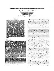
v[n] = [ v1 [n] v2 [n] L vs [n] ]T . Matrices A, B, C and D determine the properties of the discrete system. The IIR (Infinite Impulse Response) digital filter is one of the possible realizations of a linear time-invariant discrete system. It is obtained by quantizing the system parameters, the input and the output signal and the partial results of arithmetic operations when calculating the complete solution. Two basic types of decomposition into state-space difference equations are known : the first canonic form (direct form transposed) and the second canonic form (direct form). Digital filters are used very often and their realization takes up considerable computation time. It is therefore important to find an optimum form of realizing them. It is characteristic of robust structure realizations that the response to initial conditions does not affect the total complete response very much. In the literature the implementation of the 2nd canonic form is mostly given here, which is however absolutely unsuitable for implementation of the IIR digital filters in fixed-point digital signal processors. The difference equations must be prepared in homogeneous form, i.e. such that the basic instruction-the multiply and accumulate instruction is made the best possible use of. It is exactly the 1st canonic form that meets this condition far better. Fig.1 gives the structure of the 1st canonic form for a discrete system of the 2nd-order.
1/b 2
a2
x[n]
v1[n] a1
v1[0]δ [n]
z− 1
x[n]
y[n]
β
− b1
z
− b0
w 1(n−1)
c(1) c(2)
Fig.1. Signal-flow graph of a 2nd-order discrete system in the 1st canonic form.
w 1(n−2)
The state-space difference equations for the system in Fig.1 are: v1 [n + 1] = a1 x[n] − b1 y[n] + v 2 [n ] , (2) v2 [n + 1] = a0 x[n ] − b0 y[n] ,
w 1(n−3)
1 { a2 x[n] + v1 [n] } . b2 For a number of common applications it can be seen that it is of advantage to use the 1st canonic form (Fig.1) in the realization of a 1st- or 2nd-order section of IIR digital filter in a fixed-point digital signal processor. Then it no longer matters whether these partial sections will be connected in cascade (series) or in parallel. This choice, however, need not be of general validity and it is necessary, from case to case, to analyse the difference equations of the respective algorithm and to rewrite them such that they are optimum from the viewpoint of the architecture used in the digital signal processor.
w 1(n− N0+1)
y[n] =
B. Zero-pole TTS Vocal Tract Model Modelling the vocal tract in TTS synthesis is an example of when it is preferable to use the 2nd canonic form [4]. A new state-space cepstral vocal-tract model has been designed, which approximates both the formants and the antiformants of the frequency response for voiced and unvoiced speech sounds. It thus differs from the currently used LPC model, which approximates the formants alone. Unlike methods of the type of PSOLA, this method provides for modelling the prosody and requires less memory capacity. The synthesis starts from the cepstral coefficients obtained by analysing the speech signal. A structure of parametric vocal-tract model is proposed, which is formed by combining type IIR and type FIR digital filters. Experiments have shown [5] that employing a type IIR digital filter of maximally 5th-order guarantees sufficient approximation accuracy for both the sampling frequency fs = 8 kHz (N0 = 26 cepstral coefficients) and the frequency fs =16 kHz (N0 = 52 cepstral coefficients). Fig. 2 gives the signal-flow graph of a vocal tract model of the 5th-order realized by a digital filter of the type of IIR, which is expressed in the 2nd canonic form.
z−1
w3(n)
w2(n)
w1(n)
−1
−1
−1
v2[0]δ [n]
v2[n] a0
y[n]
4 9
v1(n)
z−1
c(1) c(2)
c(3)
c(3)
c(N0−3)
c(N0−2)
z
−1
v2(n)
w4(n)
w5(n)
w6(n)
1 7
1 4
1
c(1) 15 v5(n)
v3(n) v4(n) z−1 c(1) z−1 c(2) c(2) c(2) w (n−2)
z−1 c(1)
5
z−1
c(3)
c(3)
c(N0−3)
c(N0−3)
c(N0−3)
c(N0−2)
c(N0−2)
z−1 c(3)
w 5(n−2)
c(N0−3)
z−1 c(N0−2)
c(N0−2)
z−1
c(N0−1) w 5(n−N0+1) c(N0−1) c(N0−1) c(N0−1) c(N0−1) Fig. 2. Cepstral vocal-tract model of 5th-order for N0 cepstral coefficients, realized by an IIR digital filter in 2nd canonic form. FIR digital filters are also realized in 2nd canonic form [4].
The 5th-order vocal tract model for N0 cepstral coefficients c[n] in Fig.2 can be represented using a set of state-space canonic equations in the optimal form: v1 [n] = c[n ]∗ w1 [n − 1], w2 [n] = α 51 v1 [n], α 51 = 1 ,
α 52 α 52 4 v2 [n], = , α 51 α 51 9 α α 53 1 v3 [n] = c[n]∗ w3 [n − 1], w4 [n] = 53 v3 [n], = , α 52 α 52 4 α α 54 1 v4 [n] = c[n]∗ w4 [n − 1], w5 [n] = 54 v4 [n], = , α 53 α 53 7 α α 55 1 v5 [n] = c[n]∗ w5 [n − 1], w6 [n] = 55 v5 [n], = , α 54 α 54 15 w1 [n] = β x[n] + w2 [n] − w3 [n] + w4 [n] − w5 [n] + w6 [n] . (3) v2 [n] = c[n]∗ w2 [n − 1], w3 [n] =
Convolution for N0 cepstral coefficients is then defined as follows: vi [n] = c[n]∗ wi [n] =
N 0 −1
∑ c[n] w (n − m) , i
m =1
for i = 1, 2, 3, ... , s , s = 5 .
(4)
By the signal-flow graph in Fig.2, output signal y[n] equals: y[n] = w1 [n] + w2 [n] + w3 [n] + w4 [n] + w5 [n] + w6 [n] .
If in this equation we now substitute the state-space variable w1[n], we obtain the following simplification:
y[n] = w1 [n] + w2 [n] + w3 [n] + w4 [n] + w5 [n] + w6 [n] = β x[n] + w2 [n] − w3 [n] + w4 [n] − w5 [n] + w6 [n] + w2 [n] + w3 [n] + w4 [n] + w5 [n] + w6 [n]
(5)
= β x[n] + 2 [ w2 [n] + w4 [n] + w6 [n] ] .
The algorithm is now optimally adapted for implementation on a fixed-point digital signal processor. It is likewise possible to choose between two types of butterfly when realizing the FFT algorithm. There are two large groups of FFT algorithms, namely DIT (Decimation in Time) and DIF (Decimation in Frequency) algorithms. From the viewpoint of algorithm homogeneity the DIF butterfly is absolutely unsuitable. Also when implementing other types of algorithm (e.g. speech synthesis via LPC in the case of GSM, type text-to-speech synthesis, etc.) it is appropriate to respect this condition of homogeneity [6]. III. PROCEDURE OF COMPILING OPTIMIZATION In parallel processing the algorithm can be realized for several input signal samples at the same time or different parts of the algorithm are processed in parallel. Using parallel processing the computation speed of algorithm processing increases substantially. The condition is that the algorithm is written by an experienced programmer directly in the assembly of the digital signal processor or that the source code written in a high-level program language (such as the ANSI-C or C++ languages), is compiled by first-rate compiler. In the optimization procedure it is not sufficient to use only hardware or software but the difference equations that describe the algorithm must be arranged and optimized beforehand in order to obtain the highest computational throughput of the digital signal processor architecture. Using the knowledge of digital signal processing, the program can be optimized and this has much influence on its size and the data processing speed. If the algorithm is theoretically well composed, both more channels and more communication protocols can be served by one VLIW digital signal processor. Compilers designed for digital signal processors are part of the IDE (Integrated Design Environment). Texas Instruments’ Code Composer Studio or Motorola’s Code Warrior can be quoted as examples. These compilers differ from the ANSI-C or C++ standard in a few details, which in the ultimate result have a considerable effect on the speed and stability of algorithm implementation. The basic difference lies in that the defined data types are fully adapted to the architecture of digital signal processor. The number of data bits and the format of storing numbers in a given code (mostly the two’s complement) correspond to the actual storage of numbers in digital signal processor registers. Another difference as regards the above standards
is the definition of macro instructions and compiler directives by means of which the programmer defines in the source code additional information. The data in question concern, for example, mutual relations between variables, rounding of values in memories, etc. This set-up information is used by the compiler in the optimization process and if used properly, this information can greatly increase the compilation effectiveness as measured by the computation demanding of the compiled binary code. Conversely, incorrect application leads to the creation of a binary machine code, which is potentially dangerous and can cause run-time errors. Two independent variables, X and Y, for example, stored in different parts of data memory can be stored in the memory or loaded from the memory in parallel. If the variables shared a common memory space, then writing a value in variable X would entail a change also in the value of variable Y. In that case the value read from Y depends on whether the reading operation is executed before or after the operation of writing into X. In the case that variables X and Y are the arguments of a function passed on by a reference, it is not possible at the time of compilation to find out whether or not the two variables share the memory space. The compiler assumes they do and creates a more secure binary machine code, which, however, requires longer and more computation demanding. IV. EXAMPLE OF GSM VOICE CODING OPTIMIZATION The source code of the GSM Half Rate codec by ETSI (European Telecommunications Standards Institute) organisation was optimized [7]. The optimization proceeded in the Code Composer Studio for digital signal processor of the C64xx series. The source code includes several functions that implement an IIR digital filter. These are functions lpcIir, lpcZsIir, lpcIrZsIir, lpcZsIirP, lpcZiIir. These functions were optimized first in the C language using intrinsic functions and compiler keywords, similar to the optimization of function iir. Second they were also optimized in the linear assembly. Average computation demand in clock cycles of these functions is shown in Table I. In the case of optimizing in the C language, computation demand decreased approximately more than 6 times, in the case of optimizing in the linear assembly the computation demand decreased as much as 7.5 times. TABLE I COMPUTATION DEMAND OF THE FUNCTIONS OF ORIGINAL SOURCE CODE, THE FUNCTIONS OPTIMIZED IN THE C LANGUAGE AND THE FUNCTIONS OPTIMIZED IN THE LINEAR ASSEMBLY.
function lpcIir lpcZsIir lpcIrZsIir lpcZsIirP lpcZiIir
original 2 735 2 248 2 048 2 229 2 744
clock cycles C language 416 360 366 379 345
assembly 348 322 294 321 298
After optimizing the above functions the other functions of source code were optimized. Average computation demand in clock cycles of the encode and decode processes is shown in Table II. In the case of optimizing in the C language the computation demand decreased approximately 5 times. In the case of optimizing in the linear assembly the computation demand decreased approximately 9 times. Thus it is possible to serve 9 times more speech channels in comparison with the original source code. TABLE II COMPUTATION DEMAND OF THE ENCODE AND DECODE PROCESSES OF THE ORIGINAL SOURCE CODE, THE SOURCE CODE OPTIMIZED IN THE C LANGUAGE AND THE SOURCE CODE OPTIMIZED IN THE LINEAR ASSEMBLY.
function Encode Decode
original 3 209 855 108 562
clock cycles C language 644 018 46 349
parts of the code written in the C language are analysed. If the total computation requirement of the algorithm is too high, the source code in the C language is modified and optimized using the directives and other tools of the compiler. When using the parallelism of instructions and data to the maximum extent there is a danger the arithmetic may be saturated. If even this measure does not help, the only thing that can be done is to optimize the critical code parts directly in the assembly of digital signal processor. This step, however, requires a very good knowledge of the architecture of digital signal processor and experience of digital signal processors that make use of pipelining and parallel processing.
assembly 327 682 44 829
V. CONCLUSION Writing algorithms in the assembly of fixed-point digital signal processors of the type of VLIW is very demanding. Several instructions are being processed in every clock cycle, their number being given by the number of active parallel units. Executing any instruction takes a different number of clock cycles. This is due to the high degree of pipelining. The program thus contains several parallel computation paths, which the programmer must follow incessantly. Under these conditions it is very easy to make a mistake. Moreover, grouping instructions into parallel paths is subject to many constraints, which are given by the architecture of the given digital signal processor. For example, if only two address buses are available, then only two values can be read from the memory in one clock cycle. All this strongly depends on the particular type of digital signal processor. By contrast, the development of programs for processors with superscalar architecture (Pentium from Intel, etc.) is simpler from this viewpoint since parallel instruction grouping is performed by the hardware unit in the processor structure (Schedule Unit). In spite of the above difficulties we often cannot avoid writing the algorithm directly in the assembly of digital signal processor since this is the only way how to achieve the maximum speed of calculating the critical parts of the source code. The proposed procedure of implementing algorithm in the VLIW digital signal processors might be as follows: • In the proposed method the difference equations or other mathematical equations are modified in order to be as homogeneous as possible. In arithmetic operations, type VLIW digital signal processors use similar principles as digital signal processors with Harvard architecture. • The algorithm is first written in the C or C++ language and its functionality and stability are tested. • When testing the digital signal processor in the IDE the computation requirements of individual functions or
ACKNOWLEDGMENT The paper was prepared within the framework of N° 102/04/1097 project of the Grant Agency of the Czech Republic. REFERENCES [1] [2] [3]
[4]
[5] [6]
[7]
S.K. Mitra and J.F. Kaiser, ed., Handbook for Digital Signal Processing John Wiley & Sons, New York, 1993 Kuo, S.M., Gan, W./S., Digital Signal Processors (Architectures, Implementations, and Applications). New Jersey: Prentice Hall, 2004. Z. Smékal, Generalized Canonic Models of the Digital Filter for Digital Signal Processing. in Proc. of the IASTED International Conf. "Applied Informatics AI-96", February 1996, Innsbruck, Austria, pp.380-383. Z. Smékal, R. Vích, Cepstral Speech Synthesis Optimised for Dual Harvard Architecture of DSP. in Proceedings of the International Conference on Telecommunications (ICT 2000), May 2000, Acapulco, Mexico, pp.244-248. R. Vích, J. Pribil, Z. Smékal, New Cepstral Zero-Pole Vocal Tract Models for TTS. in Proceedings of the International Conference EUROCON '2001, July 7-9, 2001, Bratislava, Slovakia, pp.459-462. Z. Smékal, M. Vondra Optimized Speech Synthesis in Digital Signal Processor using the Cepstral Model of Vocal Tract in 48th International Scientific Colloquium Technical University of Ilmenau, September 22-25, 2003. ETSI EN 300 969 V8.0.0: 2000-07. Digital cellular telecommunications system (Phase 2+); Half rate speech; Half rate speech transcoding (GSM 06.20 version 8.0.0 Release 1999).