Proceedings of TMCE 2008 Symposium, April 21–25, 2008, Izmir, Turkey, edited by I. Horv´ath and Z. Rus´ak c Organizing Committee of TMCE 2008, ISBN 978-90-5155-044-3
DIRECT MERGING OF TRIANGLE MESHES PRESERVING SIMULATION SEMANTICS FOR FAST MODIFICATION OF NUMERICAL MODELS Ruding Lou LSIS Laboratory - UMR CNRS 6168 CER ENSAM France
[email protected]
Alexei Mikchevitch Research and Development Direction EDF Group France
[email protected]
Jean-Philippe Pernot ´ Philippe Veron LSIS Laboratory - UMR CNRS 6168 CER ENSAM France {jean-philippe.pernot, philippe.veron}@aix.ensam.fr
ABSTRACT
1. INTRODUCTION
Nowadays, most of the numerical product behavior analyses are carried out following four steps: Computer Aided Design (CAD) modeling, mesh definition, Finite Element (FE) simulation and results analysis. This process can be completed by optimization loops. In the context of current maintenance and lifecycle problems, the product is already designed, and its behavior has to be studied and improved during its exploitation. For the maintenance of the EDF power plants, it is critical to identify the problem source and to provide the adopted solution in a short time. In this paper, we propose a method to enable the direct modification of 2D FE models for fast and accurate FE simulation. This approach enables to avoid both multiple iterative updatings of the CAD model and the remeshing problems of complex shapes while reusing the exiting meshes together with the semantic data useful for FE simulation. Starting from existing triangle meshes to be merged, the algorithm removes the intersected faces and fills in the created holes while ensuring that the semantics initially associated to the meshes is preserved. The holes filling algorithm is driven by an aspect ratio factor which ensures that the produced triangulation fits well the FE requirements.
One of the missions of the engineering and research departments of the EDF Group, leader of the European energy market, consists in both analyzing the difficulties encountered on EDF production sites and proposing/evaluating adapted answers while satisfying the triple: Time, Quality and Cost. These expertises often correspond to analyses of the EDF production installations in the contexts of maintenance, lifecycle assessment or behaviors improvement. The aspects of time and quality of the analyses are crucial in the context of the EDF operational studies whose duration do not exceed two months. The optimized solution has to be provided quickly while ensuring its effectiveness as well as the satisfaction of power production safety criteria. As a reference, the total cost of one day of stop of a nuclear power station represents several hundreds of thousands of euros.
KEYWORDS Finite element analysis, maintenance, mesh modification, mesh quality, semantics
In this context, it seems quite clear that the reduction of the time of the projects (operational study and/or solution optimization) carried out by the EDF engineering departments may lead to important research perspectives in terms of rapid numerical prototyping and solution assessment methods. This reduction concerns the time spent notably for the various numerical simulations (e.g. mechanical resistance evaluation, vibration analysis, contra-expertise). In certain cases, the model preparation step, including the
119
CAD modeling, the development of complex meshes adapted to specific FE simulations, the accurate identification of the unknown parameters (e.g. geometrical and mechanical), the prototyping and assessment of the proposed solution can exceed 50% of the operational study full time. The automatization of the numerical analysis various steps (e.g. CAD, particular meshing, complex FE simulation) as well as the reduction of their number (less design/optimization loops, efficient exploitation of existing numerical prototypes, etc.) can both help reducing the time of study. These are the two main research directions currently followed by the EDF research departments and presented in this paper. In a first time, we propose a new prototyping method which does not necessarily go back to the CAD models during the optimization phases. Actually, the idea is to enable direct modification of the FE meshes while taking care of the semantic information (e.g. boundary conditions, groups of nodes/faces). Thus, many underlying problems are circumvented and the time of study is reduced. Secondly, we further amplify the positive repercussions while proposing a set of methods, models and tools for the efficient manipulation of both complex meshes and associated semantic data. More precisely, this paper addresses the way two meshes can be merged together while maintaining the notion of group affected to the mesh entities. The proposed approach is particularly efficient in the case of numerical prototyping of local structural modification of a given production installation. The paper is organized as follows. First, the constraints characterizing the particularities of the EDF engineering projects are presented (section 2). A digital prototype example is detailed together with its associated problems and solutions. The new prototyping approach is also proposed. Section 3 depicts a state-of-the-art of the methods enabling local mesh modifications. Based on this analysis, we introduce our triangle meshes merging approach together with the associated algorithms (sections 4 and 5). The overall process and algorithms are finally tested on an industrial example coming from an EDF project (section 6). The last section concludes this paper while coming back on the achieved results and potential future developments.
2. EDF ENGINEERING PROJECTS 2.1. Industrial study context The expertise of problems taking place on EDF production centers corresponds to the analysis of normal
120
functioning of power production equipment. Such expertises are generally performed in the context of planned preventative and/or occasional maintenance of machinery, lifecycle assessment or improvement of the production equipment behaviors (e.g. mechanical, acoustic or hydraulic behaviors). They have to satisfy various constraints like: • to answer the power production safety criteria; • to guarantee the continuity of production and to avoid the stop of production cells, • to improve the equipments’ functioning, to propose the optimal exploitation regime, etc. The taking into account of all these constraints is particularly important during operational studies where it is critical to provide quickly the optimized solution and to ensure its effectiveness. In the case of behavior improvement studies applied to maintenance/lifecycle context, solely some local modifications are possible. Actually, it is not allowed to propose global modifications on the power product installations submitted to specific exploitation constraints and provided by the specialized equipment certified designer. Moreover, each structural change, even a small local modification, requires product cycle stops and validation expertises accomplished by competent safety authorities. Hence, the solutions requiring significant modifications needing long stops of production centers and complete review of a new production cycle are not realized.
2.2. Current industrial prototyping methods and underlying problems The preparing of digital prototypes for FE analysis is generally carried out following two stages: the CAD mockup development and the generation of mesh model adapted to a given FE code. Classically, the evaluation of alternate solutions improving the structure behavior requires several returns to the CAD model describing the structure’s initial geometry. Today, such returns are generally translated by updating the given CAD models. This method is largely widespread in industrial design companies. However, its use is not always obvious during the fast studies applied to maintenance/life cycle problems. Such an approach requires the access to the design history, also called the construction tree, of all the components forming the CAD model. This is not always possible, particularly, when the geometries are translated using neutral formats (e.g. iges files) or when the CAD model is reloaded with different versions or releases
Ruding Lou, Alexei Mikchevitch, Jean-Philippe Pernot, Philippe V´eron
of a given CAD system. Moreover, some complex meshes of large size can contain many different entities difficultly modeled in the CAD mockup: double mesh elements, specific groups to model a complex phenomenon (e.g. crack, contact), semantic data to apply specific relations or boundary conditions (BCs), free/mapped and/or adaptive mesh partitions linked, etc. If the designer has to go back to the CAD model, he/she loses the information that will have to be redefined later on.
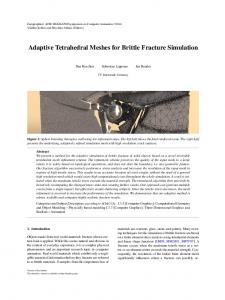
Figure 1 Local structural modifications of a caisson (a) realized on the CAD model (b) before the remeshing (c) and the redefinition of the semantic data (courtesy EDF R&D)
To illustrate these limits, we consider the example of Figure 1 that presents complex models the EDF engineers have to face. Figure 1a shows the CAD model of a caisson which a structural modification has to be performed. It corresponds to a local caisson model developed for fast structural behavior analysis with prototyping of an envisaged solution. According to the traditional prototyping method, this study would include the following steps: • development of the complex CAD model which does not exist (Figure 1.a); • development of an adapted mesh taking into account different aspects such as mesh quality criteria, mechanical modeling hypotheses and semantic data definition (30 mesh groups in this example). The example of Figure 1.c shows a complex FE model, containing 1D- and - 3D elements and adapted for particular FE analysis; • tuning/validation of the FE model through experimental results; • FE analysis taking into account the mesh, the
modeling hypotheses and the semantics useful for FE simulation (mesh groups describing the links between the 1D and 3D model partitions, mesh groups characterizing several materials, differenced by color on Figure 1.c, or mesh groups defining BCs); • prototyping of the envisaged solution (incision of the stiffener in the present case, Figure 1.b) by updating the initial CAD model; • return back to the second step in order to evaluate this solution. Here, it seems quite clear that the return to the CAD geometry is not the most pertinent method to implement a structural modification. This is especially true when the model contains a huge amount of semantic data like mesh groups. For example, some EDF models can contain up to 500 mesh groups dedicated to the FE analysis (BCs, link relations, different behavior laws or geometrical parameters, mechanical modeling of specific phenomena, etc.) as well as particular post-processing. Unfortunately, current commercial CAD systems do not make it possible to automatize the process of complex mesh creation and modification. As a result, the prototyping/evaluation of structural modifications representing even a small local change necessitates expensive complete updating of numerical model that is critical for fast studies.
2.3. A new digital prototyping method The previous subsection has demonstrated the need for developing a new digital prototyping method. The main idea lies in the reduction of the number of steps necessary to the model preparation during an operational study. In this paper, we envisage the direct treatment/manipulation of complex meshes (e.g. particular non-conform models, meshes containing a large number of semantic data necessary for EF simulation). This is to avoid the time consuming iterations that have been presented in section 2.2. Such an improvement of the design process is illustrated on the Figure 2. Today, the product behavior analyses are classically carried out following four steps: CAD modeling, mesh model preparation, boundary conditions and behavior law specification, FE simulation and results analysis (dot lines of the Figure 2). These steps are often executed several times in loop until the results are satisfactory. This is time consuming. In the proposed approach, the numerical simulation chain applied to maintenance and lifecycle problems differs from the previous one. It takes into account the fact that the product is al-
DIRECT MERGING OF TRIANGLE MESHES PRESERVING SIMULATION
121
tion of a mesh and so on. In other words, at least all the operators that are available on the CAD models should be extended to the manipulation of meshes potentially made of a set of triangles, tetrahedra, or any combination of meshes, possibly non manifold. Unfortunately, current commercial CAD software do not favor such a direct approach. Some CAD systems R R R such as IDEAS , LMS Virtual.Lab , SALOME propose limited functions enabling solely the assembling of particular 2D meshes. Consequently, structural local modification based on the method of direct mesh manipulation (section 2.3) seems an interesting alternative to the classical digital prototyping technique (section 2.2).
2.4. Merging of triangle meshes
Figure 2 Classical design process (dot lines) vs. our design process adapted to the maintenance and lifecycle problems (continuous lines)
ready designed and the product behavior has to be optimized while evaluating quickly several solutions. The proposed method is particularly interesting in the case of so-called “dead” meshes, i.e. numerical models whose associated CAD data are unavailable (e.g. inexistence of the CAD data, CAD model coming from an external software, tuned and validated mesh/FE model). The idea is to remove the hard steps of CAD modification, remeshing and complex model preparation in order to bring local modifications directly onto the initial mesh while keeping and potentially transferring the semantic data. Figure 1 shows how the CAD modifications are replaced by equivalent operations achieved directly onto the mesh (continuous lines). This process is particularly efficient when prototyping local structural modifications of a given production installation (e.g. addition or incision of stiffeners) as it has been illustrated with the example of Figure 1. To be efficient and to enable a real reduction of the time of study, the set of mesh manipulation operators has to answer all the needs the designers may one day have. One can quote the merging of two meshes, the definition of blending radii directly onto the mesh, the deletion of features having a low influence on the simulation results, the global deforma-
122
In this paper, we do not pretend to answer all the needs in term of mesh manipulations. Actually, we have been interested in the definition of a set of models, methods and tools to directly merge two triangle meshes while keeping intact the potentially associated semantic data. Such configurations are recurrent in the EDF projects. More precisely, two different merging modes are here distinguished: the face/edge and face/face modes (Figure 3). Two triangle meshes will intersect according to the face/edge mode when the intersection interface is constituted of triangles that intersect significantly, i.e. while forming angles superior to a given threshold. At the opposite, two meshes will be in contact according to the face/face mode when the angles between the triangles involved in the contact are smaller than the threshold. The algorithms developed in this paper aim at enabling the merging of two triangle meshes, in both modes, in order to produce a single mesh supporting the semantic information of the two initial meshes. Obviously, these algorithms take into account the accuracy considerations in the detection of the contact interfaces.
Figure 3 The face/edge (a) and face/face (b) merging modes
Ruding Lou, Alexei Mikchevitch, Jean-Philippe Pernot, Philippe V´eron
3. RELATED WORKS The semantic aspects have been widely detailed and exemplified in the (Aim@Shape, 2004-08) European Network of Excellence. In industrial design, the semantic data correspond to all the information that are used to design and manufacture a product: its colors, its material, its decomposition into meaningful areas (neck, door, handle). In the context of FE simulation, they may correspond to all the data that are required before running the simulation properly saying: the boundary conditions, the thickness of a group of faces and so on. Actually, the semantic aspects can be encountered in all the steps of the product lifecycle. To the best of our knowledge, the preservation of the simulation semantics during the merging of two triangle meshes has not been addressed yet. Most of the existing methods treat the problem on a geometric point of view while forgetting that the geometry is often used as a support used to convey semantic information all along the design process. Hence, a specific effort has to be done in this direction. Concerning the geometric aspects, (Chouadria & V´eron, 2006) present an approach to simplify polyhedral assemblies. The contact faces between interacting objects are identified and specific operators are applied to merge the two parts. The approach allows checking and maintaining a global consistency of the assembly model to ensure the reliability of the future processes. In their work, the notion of contact is restricted to configurations where the faces in contact are more or less parallel. In addition, the constraints relative to the shape of their triangles are different from our needs in term of equilaterality. This is due to the fact that their models are dedicated to the simulation of assembly/disassembly steps. (Jin et al., 2006) have developed a functional blending based mesh fusion method to join two or even more objects. Such an approach can be interesting in configuration where two meshes that are not in contact have to be merged. In this case, a socalled blending surface is computed so that it satisfies specific continuity conditions at the boundaries of the meshes. The cubic Hermite surface is then tessellated. This approach gives good results according to visualization criteria. Unfortunately, the fact that the transition surface is hardly controllable reduces its interest in the industrial context. (Liu et al., 2005) bring us a method enabling the blending of triangle meshes with arbitrary connectivity. The
proposed method is based on a rolling ball whose radius is user-defined. This method is interesting in our context. It could enable the direct specifications of blends over a mesh or between two meshes. The method suffers from mesh parameterization problem. (Smith & Dodgson, 2006) have been working on a topologically robust algorithm for Boolean operations on polyhedral boundary models. The algorithm is based on a series of interdependent operations thus ensuring a consistency in the intermediate results that guarantees correct connectivity in the final result. The efficiency of their algorithm still has to be demonstrated on real test cases. (Graysmith & Shaw, 1997) have proposed a method to join two meshes or to impose a new surface mesh on a volume mesh. The algorithm consists in 4 steps: contact detection, shell construction, element creation within the shell and mesh assembly. However, the quality of the elements in the contact area does not fit the FE requirements. Such a method is not adapted to the treatment of meshes of heterogeneous sizes. The approach of (Lira et al., 2002) is certainly the one which best fits the EDF requirements. Starting from two intersecting meshes, the algorithm computes the potentially multiple intersections. The modifications solely affect the elements that are directly involved in the intersection. Thus, degenerated triangles, i.e. triangles defined by one or two small angles, may be created. This is not acceptable. To circumvent this problem, not only the elements intersecting have to be treated but all the elements in a close bandwidth. This could enable the smoothing of the transition between the two meshes that are potentially of heterogeneous sizes.
4. TRIANGLE MESHES MERGING APPROACH In order to be able to treat the previously introduced two merging modes while enabling an adaptive remeshing of the contact interfaces, a generic three steps approach is proposed and illustrated on the basic example of Figure 4: • interfaces detection and intersections computation; • contact interfaces cleaning; • contact interfaces remeshing. Depending on the merging mode, this generic approach slightly differs. When treating the face/edge merging mode, the first step corresponds to the iden-
DIRECT MERGING OF TRIANGLE MESHES PRESERVING SIMULATION
123
the two while projecting the involved nodes on each other parts. The semantics relative to the FE models is directly treated within the three previously introduced steps such that no information is lost. To this aim, two first operators are defined: • the maintenance operator ensures that the unmodified entities preserve their initial group assignment. It also updates the groups during the cleaning operations; • the inheritance operator ensures that the entities newly inserted in a mesh (nodes and/or triangles insertion during the filling of holes) inherit of the groups affected to the entities they are replacing. For example, if a set of faces own the same group assignment, the faces that are newly created during the remeshing step inherit of this assignment.
Figure 4 Various steps to merge two meshes in the face/edge mode
tification of the triangles that are intersecting and to the computation of their intersections (Figure 4.a to 4.d). It returns a set of polylines. In the face/face merging mode, the computation of the intersections differs since the objective is to define the boundaries of the contact interfaces. The second step is common to the two modes. It suppresses the triangles that are involved in the contact interface and in its close neighborhood (Figure 4.e). At the end of these two steps, a set of hole contours and, potentially, a set of polylines are obtained. In the third step, the holes are filled in while satisfying the constraints relative to the polylines (Figure 4.f). The algorithm is driven by an aspect ratio criterion to ensure that the quality of the produced meshes matches the FE requirements. On the basic example of Figure 4, four holes have been filled in. New nodes are potentially inserted to enable smooth transitions between triangles of heterogeneous sizes. In some specific cases encountered by the EDF engineers, it can also be interesting to preserve the interfaces between two meshes that have to be connected in the face/face mode. In this case, the cleaning step is modified to enable either a deletion of solely one of the two parts in contact, or a merging between
124
Of course, these two operators do not pretend to cover all the needs relative to the transfer of semantic information when merging two FE meshes. In the future, we would like to investigate on the definition of an exhaustive set of operators enabling not only the maintenance and inheritance of the simulation semantics but also their propagation (Figure 5).
Figure 5
Example of semantic propagation
5. DETAILS OF THE ALGORITHMS In this section, Mesh1 and Mesh2 are the two meshes that have to be merged.
5.1. Contact interfaces detection This step aims at finding the faces that are potentially in contact, either in the face/edge or face/face modes. The algorithm is based on the work of (Chouadria & V´eron, 2006). It consists in the detection of the intersections between scaled bounding boxes built on each face of the two meshes. The bounding box of a face is computed along the parametric directions and scaled with an empiric factor of 1.05 to avoid inaccuracy problems. It results that the number of
Ruding Lou, Alexei Mikchevitch, Jean-Philippe Pernot, Philippe V´eron
detected intersections can be greater than the number of real couples of faces in contact. The outputs of this step are two arrays F1 and F2 containing respectively some faces of Mesh1 and Mesh2. The ith face of F1 is potentially in contact with the ith face of F2 . The Figure 4.b shows the result of this algorithm applied to the basic example of Figure 4.a.
5.2. Triangles intersection computation and intersection lines definition Once the two arrays of faces are obtained, the triangle/triangle intersection algorithm starts. For each couple of faces (f1, f2), the intersections between the edges of f1 and the face f2 as well as the intersections between the edges of f2 and the face f1, are computed. This algorithm is run over the entire sets F1 and F2 . It results in two arrays of intersection nodes N and intersection edges E. Since the bounding boxes used to build F1 and F2 are along the parametric directions and since the bounding boxes are slightly scaled, some couples of faces contained in F1 and F2 may not be intersecting.
5.3. Intersection line optimization As shown on the result of Figure 4.c, the intersection between two meshes may lead to an intersection polyline defined by a non uniformly distributed set of nodes. This situation is even more amplified when the mesh densities are significantly different around the contact interface. Since this polyline is used as a basis for the remeshing of the contact interface (see section 5.5), it is mandatory to improve the distribution of nodes such that the inserted triangles will be as little degenerated as possible. This is an important constraint for the forthcoming FE simulation. To do this, a distance criterion is adopted and ensures that the distances between the successive intersection nodes are more or less equal. An angle criterion is also used to identify the important nodes that should be kept in the optimized version. The optimization of the number of nodes as well as their positions depends on the edge average length criterion which is initialized while computing the average length ℓa of the edges of the triangles that have been identified in the array F1 and F2 (section 5.2).
In this case, these two arrays are updated so that they solely contain the faces that are really intersecting. The Figure 6 shows the several cases that may be encountered when computing the intersections between two triangles. Given the two arrays of intersection nodes N and edges E, the intersection lines are built. These polylines can either be closed or open. They can also own one or several branches. Figure 4.c shows the result of this algorithm on the previously introduced basic example. A more complex test case is shown in section 6.
Figure 7 Intersection line optimization according to the ℓa average length criterion Figure 6 Non exhaustive list of intersection configurations between two triangles
The algorithm used to compute the contact interface boundaries (case of the face/face merging mode) is not presented here. It exploits partially the work of (Chouadria & V´eron, 2006) on the detection and merging of contact interfaces between two polyhedra. In their work, the authors do not take care of the aspect ratio criterion that is crucial for FE analyses.
The overall algorithm is illustrated on the example of Figure 7. It shows a ruler whose basic unit is equal to ℓa and the five steps of the optimization process corresponding to the treatment of the nodes n2 to n6 . To ease the understanding of the algorithm, the polyline is here deployed and the nodes are spread according to the curvilinear position they have onto the 3D polyline. The ruler is located so that its left extremity matches the first node n1 . The following algorithm is then run for all the nodes nk between the second and last nodes.
DIRECT MERGING OF TRIANGLE MESHES PRESERVING SIMULATION
125
Compute the distance ℓk−1,k , being ℓi,j the curvilinear distance between the two nodes ni and nj . if nk is not a particular node (see below) then if ℓk−1,k > ℓa . then nk is kept else nk is deleted. end if end if A node nk is a so-called particular node if one of the three following configurations is encountered: • nk is on the boundary of the mesh. This is to avoid the modification of the boundaries; • nk has been produced by a non-manifold edge. In this case, this node is important since it enables the connection between several branches of the intersection lines; • the angle between the segments [nk−1 nk ] and [nk ,nk+1 ] is too small. This is to avoid the loss of important shape features.
5.4. Contact zone cleaning In order to prepare the generation of triangles satisfying the FE analysis requirements, i.e. as equilateral as possible, not only the triangles involved in a contact interface have to be deleted, but also those which are in its more or less close neighborhood. This is especially true when the two meshes that have to be merged own very different triangle densities. For a given intersection line, potentially defined by one or several branches, the notion of neighborhood is defined increasingly as follows: • the first neighborhood of the polyline, or the neighborhood at the first order, gathers together all the triangles of the contact interface, i.e. all the triangles contained in F1 and F2 ; • the second neighborhood of a polyline gathers together all the triangles defined by at least one of the three nodes of at least one triangle included in the first neighborhood of the polyline; • by generalizing, the ith neighborhood of a polyline gathers together all the triangles defined by at least one of the nodes of at least one triangle included in the (i-1)th neighborhood of the polyline. If a polyline has no ith neighborhood, there will be no neighborhood of higher order.
126
Given these definitions and corresponding algorithms, it is easy to identify the various neighborhoods of the intersection lines. Thus, to delete the faces included in a bandwidth of Nb triangles around an intersection line (Nb ≥1), all the triangles of the neighborhoods having an order varying from 1 to Nb are recursively deleted. The result of Figure 4.e has been obtained while deleting the triangles in the first neighborhood of the intersection line (Nb =1). In order to automatize the instantiation of the bandwidth control parameter Nb , a specific algorithm is proposed. It takes into account both the ratio between the densities of the two meshes, which can be more or less equal, and the minimum distance from the intersection line to the boundary of its first order neighborhood, which can be more or less equal to the half average length ℓa /2. The algorithm can be written as follows: Compute the two average edge lengths, respectively ℓ1a and ℓ2a , of the triangles respectively contained in F1 and F2 (section 5.1); Compute Nb = Round[max[ℓ1a , ℓ2a ]/min[ℓ1a , ℓ2a ]] if Nb = 1 then Compute ℓmin the smallest distance from the intersection line to the boundary of its first neighborhood; Nb = Round[max[ℓmin , ℓa /2], min[ℓmin , ℓa /2]];
Nb = min[Nb , 2]; Delete[Mesh1, F1, Nb ]; Delete[Mesh2, F2, Nb ]; else if max[ℓ1a , ℓ2a ] = ℓ1a then Delete[Mesh1, F1, 1]; Delete[Mesh2, F2, Nb ]; else Delete[Mesh1, F1, Nb ]; Delete[Mesh2, F2, 1]; end if end if The “Round[x]” operator returns the closest integer to the real “x”. The “Delete[mesh, F, n]” function deletes all the triangles of “mesh” included in the neighborhood of order “n” of the intersection line whose first neighborhood is defined by “F”. When computing ℓmin , the nodes of the intersection line that are on the boundary of the contact interface are not considered. The cleaning algorithm has been run on the two examples depicted on Figure 8.
Ruding Lou, Alexei Mikchevitch, Jean-Philippe Pernot, Philippe V´eron
zero corresponds to flat triangles. It is commonly accepted that a triangulation is a good one, with respect to the FE approximation, if the aspect ratio of the worst triangle is greater than 0.5. Being define this indicator, the Liepa’s algorithm is upgraded so that the triangulation maximizes the aspect ratio Q of the triangle inserted at each step. The result of our remeshing algorithm is illustrated on the Figure 9.b.
Figure 8 Contact zone cleaning when merging two meshes having a similar average edge length
5.5. Contact zone remeshing Once the contact zone has been cleaned, the newly created holes have to be filled in. To this aim, the algorithm of (Liepa, 2003) is adapted and modified to answer the FE requirements. Given a hole contour, his algorithm builds iteratively a triangulation so that its area is minimum at each step. If this algorithm is applied to the filling of the four holes that have been created on the basic example of Figure 4.e, the resulting triangles are degenerated and some others are flat (Figure 9.a). This is due to the fact that Liepa’s area criterion is not adapted to the triangulation of a planar hole (i.e. a hole whose contour is included in a plan). Effectively, on the example of Figure 9, the area of the created triangulations is constant whatever the admissible configurations are. This does not fit the FE requirements. To circumvent these limits, another criterion is here proposed together with its optimization method. A degenerated triangle is characterized by exactly one or two small angles. To quantify the degeneracy of a triangle without computing the three angles, we use an indicator introduced to check the quality of FE meshes (Ciarlet, 1978) and defined as follows: Q=α
S hp
(1)
√ is the aspect ratio of a given triangle with α = 2 3 a normalization coefficient so that Q = 1 for an equilateral triangle, h is the longest edge length, S is the area of the triangle and p its half-perimeter. This quality factor belongs to the interval [0, 1]. The limit
Figure 9 Comparison between the minimum area (a) and the maximum aspect ratio (b) triangulation criteria
5.6. Optimization of the triangulation This optional step can be decomposed in two successive algorithms that work as follows: • insertion of new nodes at the centroid of some triangles and swap of edges so that the optimized triangulation approximates the density of the surrounding meshes. This is especially interesting when the two meshes own triangles of heterogeneous sizes in the filled area. The algorithm is an adaptation of the one of (Pfeifle & Seidel, 1996) so that the swap operation is driven by the aspect ratio Q of the concerned triangles. • deformation of the filled area so that the connections between the inner and surrounding meshes satisfies either position, tangency or curvature blending conditions. This step fully exploits the work of (Pernot et al., 2006). This step is mandatory when the intersection occurs in a non-planar area. This step is not mandatory on the example of Figure 9.b since the two meshes are of heterogeneous sizes.
6. APPLICATION TO EDF PROJECT The proposed approach has been tested and validated on an EDF operational project requiring a fast study
DIRECT MERGING OF TRIANGLE MESHES PRESERVING SIMULATION
127
of the mechanical behavior of a caisson. More precisely, this caisson had to be rigidified by inserting several stiffeners in the appropriate directions. Figure 10.a represents a possible solution to this problem. Both the static and dynamic behaviors of the structure are improved. In this section, we compare the newly developed approach (fast prototyping of the structural modifications using an existing numerical model, i.e. a dead mesh) to the one which consists in performing the modifications on the CAD model.
software. It is called the “reference” model. It corresponds to a conform mesh assembly, i.e. without connection problems between mesh entities, taking into account different meshing quality criteria (goodshaped elements, absence of double nodes, etc.). The results of the FE analysis based on such a model are also considered as references according to the proposed prototyping method.
6.1. Comparison of the times of study The first comparison is qualitative and is relative to the time necessary to optimize the number, the size and the position of the stiffeners. On the one hand, our method requires two main steps: development of the stiffeners 2D numerical model, and merging of the two 2D meshes (initial model of the caisson with the new model of the stiffeners) while transferring automatically the semantic information to the resulting mesh. Alternate configurations can be tested directly onto the initial mesh without going back to the CAD model. On the other hand, the use of the classical method requires four steps: design of the caisson’s and stiffeners’ CAD models, assembling of the two CAD models, meshing of the resulting CAD model and transfer of the simulation parameters from the “dead” mesh to the new mesh. Since the initial CAD model of the caisson did not exist in this project, the use of the classical method had required its design starting from scratch, which is a time consuming task. In addition, the evaluation of different positions and sizes of the stiffeners requires several loops of CAD modifications, meshing, transfer of semantic data which does not tend to reduce the time of the study.
6.2. Comparison of FE analysis results Presentation of the two models The comparison is done between the results of two FE analyses performed using two 2D meshes which differ at the level of connection mode between the caisson and added stiffeners but having similar mesh smoothness considered optimal. The first model results from the classical prototyping method. It includes all the components assembled on the CAD level (initial model of the caisson and new model of the stiffeners in our case). The upR dated model has been developed using the IDEAS
128
Figure 10 Overall merging approach on the example of two stiffeners that have to be merged with a caisson model (images from XDS)
The second model has been obtained by merging the caisson and stiffener mesh models following the technique proposed in this paper. Conform mesh assembly has been achieved using new mesh merging operators developed in the XDS software under a research contract between the EDF Group and LSIS Laboratory. The inputs/outputs are preformed R which enables in the UNV file format of IDEAS the specification of groups between the FE entities. Figure 10 shows how the multiple input meshes (Figure 10.a) are treated to obtain a single mesh while keeping intact the semantic information (Fig-
Ruding Lou, Alexei Mikchevitch, Jean-Philippe Pernot, Philippe V´eron
ure 11.e). The different colors represent the group assignments. The algorithm first detects the contact interfaces, computes the intersection lines, optimizes the number of intersection nodes and cleans the contact interface (Figure 10.b and Figure 10.c). Here, the meshes are of homogeneous sizes and the cleaned area has a bandwidth of one. Thus, for each newly inserted stiffener, 22 holes appear on the caisson and 7 on the stiffener. These holes are then filled in using the newly developed quality criterion (Figure 10.d) and the group assignments are transferred onto the newly created elements (Figure 10.e). Comparison of the FE analysis results The various FE analyses have been carried out using R software, a free FE code recogthe Code ASTER nized by the French Nuclear Safety Authority. It is developed and distributed by the Research and Development Division of the EDF Group. The postprocessing of the results has been done using the R software platform, a free CAD / Mesh / SALOME FE Analysis / Post-processing software co-developed mainly by the Open CASCADE company, the EDF Group and the CEA with some contributions of other industrial and university partners. Table 1 Comparison of the two prototyping methods on R statics analysis results of Code Aster Von Mises stress state, MPa Numerical prototyping methods
σmax on stiffeners (local stress)
σmax on caisson wall
Classical method: reference solution
150
72
Proposed method: assembling by local remeshing
127
77
The first results concern the analysis of the mechanical resistance of the structure under exploitation conditions. The caisson is submitted to an internal pressure and rigidified using the added stiffeners. The Figure 11.a and Figure 11.b show a cartography of the Von Mises Criterion stress for each of the two prototyping methods. Table 1 summarizes the statics
Figure 11 Stress state of the caisson: (a) case of reference model; (b) case of the new prototypR , couring method (images of SALOME tesy EDF R&D)
analysis results. In both case, the internal pressure of the rigidified caisson involves a stress concentration phenomenon. Thus, the small difference between the maximal values of equivalent stress constraints evaluated at the geometrical singularity locations was predictable. The Von Mises stress at the other locations is very similar in both cases. The maximal relative error, obtained when comparing the stress of the new method to the stress of the reference solution, is about 10% which is acceptable for fast industrial studies. The second results concern the study of the dynamics behavior induced by vibration forces due to turning machines usually present on power production centers. Such an analysis enables to verify if the locally modified structure does not generate resonance phenomena during its dynamics excitation. The Figure 12 shows some natural modes of the modified caisson resulting from a modal FE analysis of the reference model. Table 2 summarizes the dynam-
DIRECT MERGING OF TRIANGLE MESHES PRESERVING SIMULATION
129
Mode 1: mode of bottom stiffeners Figure 12
Mode 2: coulped “pomp” mode of the caisson/top stiffeners
R , courtesy EDF R&D) Examples of caisson natural modes: case of reference mesh (images of SALOME
Table 2 Comparison of the two modeling strategies on R modal analysis results of Code Aster Natural modes of the structure
1 (triple mode) 2 3 (triple mode) 4 5 6 (double mode) 7 8
Frequencies, Hz Classical Proposed method: method: reference assemblage by soution local re-meshing 114 114 185 177 209 209 249 259 251 294 252 252 266 268 272 277
ics analysis results. The natural modes 2, 4, and so on, are the modes (coupled or not) of the caisson and top stiffeners added to the structure. They correspond to the low-frequency band. The frequencies obtained using the proposed prototyping method are very close to those of the reference solution. The relative errors between the frequencies computed with the new and older mesh assembly methods vary from 0 to 10% without exceeding 5% in average, which is acceptable for operational studies. Moreover, no mode has been lost in the considered band, which is crucial for the analysis of large-size structures in the low-frequency domain. Finally, one can notice that the conform assembly of independent meshes using the proposed mesh merging method does not introduce complementary specific BCs on the level of the connections of the new mesh components to the initial structure, which is another usually used industrial practice. Geometrically conform mesh assembly makes it possible to model accurately the mechanical behavior of the structure, i.e. to avoid a phenomenon of local over/underrigidification of the structure. The taking into ac-
130
Mode 3: coupled mode of the caisson/top stiffeners
count of meshing quality criteria (e.g. equilateral elements and sufficient smoothness of the mesh) improves the simulation result that allows to converge to the exact solution of the problem. This aspect is critical for operational engineering projects taking into account particular requirements like safety and normal functioning of power product installations.
7. CONCLUSION In this article, a new digital prototyping method has been proposed to avoid time consuming manipulations involved when performing a classical optimization loop on the CAD Modeling, Meshing and Simulation steps. The main idea lies in the direct manipulation of the meshes together with their associate semantic data. Hence, the structural modifications are not anymore performed on the CAD model, which may not exist, but directly on the mesh. More precisely, a set of methods, models and tools have been developed to ease the merging between two triangle meshes. The semantics useful for FE simulation (i.e. FE groups defining BCs, heterogeneous materials, link relations, etc.) are transferred onto the resulting merged mesh. The advantages of such a method have been demonstrated through examples coming from EDF industrial projects. In the future, such an approach should be extended to the other types of mesh the EDF engineers use. The new research directions concern the definition of 3D mesh (e.g. tetrahedral) manipulation operators as it already exists for CSG and B-Rep models. In addition, the library of operators working on the semantic data should be enlarged to better cover the needs.
8. ACKNOWLEDGEMENTS This work has been carried out under a Research Contract between the Research and Development Direction of the EDF Group and the LSIS laboratory.
Ruding Lou, Alexei Mikchevitch, Jean-Philippe Pernot, Philippe V´eron
REFERENCES Aim@Shape 2004-08, “Advanced and innovative models and tools for the development of semantic-based systems for handling, acquiring, and processing knowledge embedded in multidimensional digital objects”, European Network of Excellence, Key Action: 2.3.1.7 Semanticbased knowledge systems, VI Framework, URL: http://www.aimatshape.net.
R Open Source Integration Platform for SALOME . Numerical Simulation. URL: http://www.salomeplatform.org/
Smith, J.M., Dodgson, N.A., 2006, “A Topologically Robust Boolean Algorithm Using Approximate Arithmetic”, 22nd European Workshop on Computational Geometry, pp. 217-220.
Chouadria, R., V´eron P., 2006, “Identifying and remeshing contact interfaces in a polyhedral assembly for digital mock-up”, Engineering with Computers, vol. 22, pp. 47-58. Ciarlet, P. G., 1978, “The finite element method for elliptic problem”, North Holland. R URL: http://www.code-aster.org/ Code Aster .
Graysmith, J.L., Shaw, C.T., 1997, “Automated procedures for Boolean operations on Finite Element meshes”, Engineering Computation: Int. J. for Computer-Aided Engineering and Software, vol. 14(7), pp. 702-717. Jin, X., Lin, J., Wang, C.C.L., Feng, J., Sun H., 2006, “Mesh fusion using functional blending on topologically incompatible sections”, The Visual Computer, 22(4). pp 266-275. Liepa, P., 2003, “Filling holes in meshes”, In Proceedings of the 2003 Eurographics/ACM SIGGRAPH symposium on Geometry Processing (SGP’03): pp. 200-205. Lira W.M., Coelho, L.C.G., Martha, L.F., 2002, “Multiple Intersections of Finite-Element Surface Meshes”, Proceedings of the 11th International Meshing Roundtable, pp.355-366. Liu, Y.S., Zhang, H., Yong, J.H., Yu, P.Q. and Sun, J.G., 2005, “Mesh Blending”, The Visual Computer, vol. 21, pp. 915-927. Pernot, J.-P., Moraru, G. and V´eron, P., 2006, “Filling holes in meshes for efficient reverse engineering of products”, Tools and Methods for Competitive Engineering (TMCE’06), vol. 1, pp. 273284. Pfeifle, R. and Seidel, H.-P., 1996, “Triangular BSplines for Blending and Filling of Polygonal Holes”, Proceedings of Graphics Interface’96, Morgan Kaufmann Publishers, pp. 186-193.
DIRECT MERGING OF TRIANGLE MESHES PRESERVING SIMULATION
131
132