and its angular resolution is limited by the beamwidth of the antenna. The crossed ... exact determination of the angle requires a knowledge of the radiation pattern of ... D.V. Thiel, S. O'Keefe and J.W. Lu, Electronic beam steering in wire. 1026 ...
51.4
Direction finding using a switched parasitic antenna array Stephanie Preston* and David V. Thiel Radio Science Laboratory School of Microelectronic Engineering Griffith University - Nathan (Brisbane) Qld 41 11 Australia
Abstract An electronically controlled antenna array consisting of one active element and a number of parasitic elements can be used for direction finding. Array directivity is controlled by exchanging the position of the feed and the parasitic elements. An array of four monopoles on a ground plane provides 360 degree azimuthal coverage with no moving parts, provides excellent directional resolution and can be controlled using a simple microcontroller. The antenna design, its application to direction finding and reliability in noisy environments are presented.
Introduction Direction finding systems are used to determine the angular position of a distant source. Applications include security systems (for the detection of illegal transmitters) and motor vehicles, aircraft, robots (for anti-collision radar and for navigation). Two or more spatially separate direction finding systems can be used to determine the exact location of a transmitter. Current direction finding antennas include mechanically rotating a highly directional array, crossed loops, and phased arrays [ 11. Mechanical rotation requires significant power to operate and its angular resolution is limited by the beamwidth of the antenna. The crossed loop structure has quite low gain. Phased antenna arrays have significant insertion loss between the radiating elements and the source, and require sophisticated computer algorithms to control the beam. A third alternative [2] was to electronically control the direction of an array by controlling the position of the feed element in an array of parasitic elements. It was demonstrated that an array of monopoles, dipoles or patches could be used to achieve 360 degree azimuthal coverage. The control electronics for a four element array of monopoles consists of a single pole, four position RF switch and TTL controlled parasitic elements. The use of a p.i.n. diode at the base of each monopole ensures that it is either shorted to ground and so will act as a reflector, or is open circuit to allow the RF signal to be applied. The array can be
0-7803-4178-/3/97/$10.000 1997 IEEE
1024
controlled by four digital control lines supplied from a small, low powered microcontroller. While it is possible to construct many different arrangements of switched parasitic antenna arrays, in this paper, attention is directed to a four element monopole antenna system (Fig. 1). The elements are arranged at the four comers of a square with a side length of 0.271. The spacing is chosen to optimise both the directional characteristics of the antenna and the input impedance. At any switch configuration, one element is active and the other three elements are shorted to ground. Thus the polar pattem can be switched to four different orthogonal directions. NEC2 modelling of this array results in an azimuthal polar pattern with a 3 dB beamwidth of 90 degrees (Fig. 2). The four element arrangement is perhaps the minimum number of elements required to ensure that a significant signal will be received with two adjacent switched positions. Further accuracy is possible if more elements are used.
Angle determination Under normal operation, the array is electronically switched to each of the four positions sequentially. The signal strengths sI, s2, s3 and s4, are detected at each of the four switch positions 0, 90, 180 and 270 degrees respectively. If there is a single signal source, the determination of the nearest 45 degree sector is achieved by simply ordering the two maximum signal strength measurements. For example if s4 and sl are the two largest signal strengths received in the scan and s4> s , , then the source is located between 270 degrees and 315 degrees. The exact determination of the angle requires a knowledge of the radiation pattern of the array. From this simple analysis, some important observations can be made:
0
The two strongest signals must lie in adjacent quadrants. Failure to meet this criteria indicates multiple sources or significant multi-path effects. This first determination is independent of the strength of the signal source provided sq and s, are greater than the noise level into the receiver. The determination is independent of the linearity of the detector.
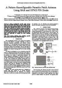
Note that as the 3 dB beamwidth is 90 degrees, the gain of the over-all array is 3 dE3 less than the maximum gain. For the monopole array, this gain is almost 11 dBi. At 90 degrees off the main beam, the gain is approximately 2 dBi. Thus, in any azimuthal quadrant, the two maximum values will lie in the range 2 to 1 1 dBi. During one scan of the azimuthal plane, the output from each of the four switch positions will be recorded. Assuming a square law detector is used the ratio of the maximum value to the next highest value is plotted as a function of angle in Fig. 3. Only the angular range from 0 to 45 degrees is given because outside this
1025
range, an adjacent switch position will provide the maximum signal detected Note that the function is monotonic and so unique angle determinations are possible The effect of noise on the accuracy of the angular determination was investigated numerically using a random number function Results are included in Fig 3 It is clear that the error in the azimuthal angle determination is larger when the ratio is larger In the results given, the noise level was 10% of the minimum signal received at the null in the polar pattem
Conclusions The switched parasitic antenna array can be used for high speed direction finding with significant accuracy using a simple microcontroller. With four elements, the antenna gain is greater than 2 dBi for the two switch positions required for an angle determination to be made. The minimum gain is -2 dBi. This gain is far greater than that of crossed loop direction finding systems. In a strong signal environment, it is possible to use all four switch position measurements to accurately determine the position of not only a primary signal source, but also a secondary signal source (eg a strong multi-path effect). Note that this type of direction finding can be achieved at quite high speed. The RF switch and digital logic switches have a rise time of less than 1 psec. The maximum speed is limited by the settling time of the detector and the speed of the ADC. Using a microcontroller with a 4 MHz clock, the time for one 360 degree azimuthal sweep and a simple comparator algorithm will be approximately 200 p e c . This is faster than a phased array or mechanical rotating direction finding system. This introduces the possibility of determining the direction of a source which is either rapidly changing in position or has a rapidly changing signal strength. Acknowledgment: S. Preston currently receives support through a scholarship provided by the CSIRO Telecommunications and Industrial Physics. References: R.E. Franks, Direction finding antennas. in Y.T. Lo and S.W. Lee, [I] Antenna Handbook vol 111, Van Nostrand Reingold, N.Y. p. 25-1 25-26, 1993.
D.V. Thiel, S. O’Keefe and J.W. Lu, Electronic beam steering in wire [2] and patch antenna systems using switched parasitic elements. IEEE AP-S Meeting Baltimore, p. 534-537., 1996.
1026
Fig. 1. Four monopole antenna elements on a ground plane.
270
Fig. 2: Relative azimuthal gain (dB)for the four different switch positions
01
-45
-40
-35
-25 -20 -15 Principal Angle (degrees)
-30
-10
-5
I
0
Fig. 3: Square law detector output ratio between adjacent switch positions. The error bars indicate the effect of a constant noise level into the detector.
1027