disassembly procedure of the notebook. Be sure to use proper tools described
before. SUS G1S Series Notebook consists of various modules. This chapter ...
detailed disassembly procedure of individual modules will be provided for your
service needs. The disassembly procedure consists of the following steps:.
Shift the gearbox into reverse gear and remove the shifting mechanism assembly
from the rear cover (three 6mm studs with 10mm wrench nuts). Be careful to ...
as originally presented on “Do it Yourself Digital Camera Repair” ... disassembly
of the camera, and are not recognized or authorized by Nikon. Follow these ...
Mar 20, 2018 - Triton X-100 (GE Healthcare, catalog number: 17-1315-01). 39. Sodium azide ..... Cells transfected with vector (Control) or Tctex-1-shRNA.
http://camerarepair.blogspot.com/. The following outlines the steps to dissect the Nikon L10. They were developed by per
4. Disassembly and Reassembly. 4-1. Disassembly and Reassembly of Q35. -
This document cannot be used without Samsung's authorization -. Part. Figure.
Feb 15, 2011 - proteins WtsE and AvrE require WxxxE motifs. Mol Plant Microbe Interact 22:703â712. 27. López-Solanilla E, Bronstein PA, Schneider AR, ...
Jun 30, 2010 - Rappsilber J, et al. eIF4A3 is a novel component of the exon junction complex. RNA 2004; 10:200-9. are transport receptors that recycle them.
through a TCP/IP connection to a robot program running on the robot controller. ... Before moving, the robot sets its light strip to red, indicating that it will start ...
OSeven's guide to the complete disassembly of the HTC Touch. OSeven is a member at www.Xda-developers.com. HTC Touch Dis
Just use a butter knife at the bottom left (screen side) edge to pry it open. Note how/where the AV cover attaches to th
completely disassemble your Xbox, therefore, parts 6 and 7 are optional. It is also
... T10: To remove Xbox 360 internal chassis from case. Metal Bar: To remove ...
Parallel bundles of actin filaments at the cortex-endoplasm interface provide tracks for myosin-generated cytoplasmic streaming in characean internodes.
Feb 21, 2007 - Finn et al. [1]. Proteins were denatured in reducing buffer (8% b- ... 15% homogeneous Laemmli gels [30], and 7.5% homogeneous Tris-Tricine.
Disassembly Procedure. Pfflilf'jlifélfifl! file iiiféimmi'iuii pmi'idm' in tile; Jemima In
Pam; file mmpfei'e fllf-Ifiiifffl'llifly premiere {if file immlmé. He mire I0 we proper ...
Mar 5, 2005 - Product configuration optimization for disassembly planning: A differential approach. Shivakumar Viswanathana, Venkat Alladab,â. aComputer ...
Aug 9, 2018 - the disassembly of actin filaments: i) not only LAT-A but also other ...... by bradykinin or mechanical force in aortic epithelial cells [103, 104], ..... The crown-of-thorns starfish genome as a guide for biocontrol of this coral reef.
modems, routers, and electric adaptors, has, however, outweighed by the ... seven products included various DSL modems and analog telephone adaptors ...
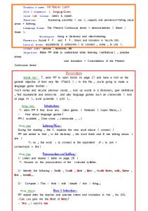
Teacher's name :Mr.Nacer Larbi file 2 sequence 1. Language Games level 2AM
lesson: Listen & speak. Function: Expressing possibility ( can ), capacity and ...
Maintenance Organisation Exposition for CAA & FAA Approved ... BM-004
Capability List will be incorporated at the 6 monthly review and sent to the CAA /
FAA.
SUS A7V Series Notebook consists of various modules. This chapter ...
Disconnect the main Antenna and open the two latches to pop the MINI PCI.
MODULE up ...
Disassembly procedure
2
Chapter
Disassembly Procedure Please follow the information provided in this section to perform the complete disassembly procedure of the notebook. Be sure to use proper tools described before.
A
SUS A7V Series Notebook consists of various modules. This chapter describes the procedures for the complete notebook disassembly. In addition, in between procedures, the detailed disassembly procedure of individual modules will be provided for your service needs.
The disassembly procedure consists of the following steps: • • • • • • • • • • • • •
Battery Module HDD Module Wireless LAN Module TV Tuner Module Second Memory Module CPU Module ODD Module Keyboard Main Memory Module Top Case Module LCD Module Bottom Case Module Motherboard Module
2-1
Disassembly procedure
B A T T E R Y
Battery Module The illustration below shows how to remove the battery module. 1.
Turn over the notebook. Unlock the battery lock (No.1).
1
2.
Slide the battery lock (No.2) and pull the battery pack out.
2
2-2
Disassembly procedure
H D D
M O D U L E
HDD Module The illustrations below show how to remove the HDD module from the notebook.
H D D
M O D U L E
R E M O V A L
Removing HDD Module
1.
Remove 2 screws [M2 * 4(L)] here. And lift the cover away.
2.
Pull out the hard drive and lift the hard drive away.
Disassembling HDD Module H D D
Remove 4 screws [M3 * 4(L)]] to separate HDD from HDD housing.
M O D U L E D I S A S S E M B L Y
2-3
Disassembly procedure
W I R E L E S S L A N
Wireless LAN Module The illustration below shows how to remove the Wireless LAN module. 1.
Remove 2 screws [M2 * 4(L)] and remove the Mini-PCI Cover away.
MINI-PCI
TV TUNER
2.
Disconnect the main Antenna and open the two latches to pop the MINI PCI MODULE up then pull it out.
2-4
Disassembly procedure
T V
T U N E R
TV TUNER Module The illustration below shows how to remove the TV TUNER module. 1.
M E M O R Y M O D U L E
M E M O R Y R E M O V A L
Disconnect the RF cable and open the two latches to pop the TV TUNER module and remove the TV TUNER module from the mini-PCI socket.
Second Memory Module The A7V Series Notebook has two expansion SO-DIMM slots for you to upgrade the total memory up to 2GB with two DDR2-533 1024 MB SO-DIMM RAM modules, here introduce you the second memory slot. Removing Memory module
1. Remove 6 screws [M2 * 4(L)] & 1 screw [M2 * 8(L)] and take the CPU door away.
M2*4(L)
M2*8(L)
2-5
Disassembly procedure
2. Remove the Memory module by opening the latches which will pop the module up to a 45° angle and then pulling out the module.
3. If there is an existing memory, remove it by opening the latches(No. 2), which will pop the module up to a 45° angle, and then pulling out the module in that angle (No. 3).
C P U
CPU Module The illustrations below show how to remove the CPU module from the notebook.
C P U R E M O V A L
Removing CPU
1.
Remove 4 screws [M2 *4(L)] by order and take the CPU heat sink module away.
2
3
3
1
2-6
Disassembly procedure
2.
Turn the non-removable screw 180 degrees counter-clockwise to loosen the CPU. Squeeze the vacuum handling pump and use it to lift the CPU away. L
O
Unlock 3. 4. 5.
Don’t touch the die above the CPU. Remove the CPU away. Remove CPU thermal pad from CPU die with a pair of tweezers.
triangle
6.
Remove 2 screws [M2 *3(L)] and disconnect the fan cable & DC-in cable & Bluetooth cable, and then take the FAN module away.
2-7
Disassembly procedure
O D D
M O D U L E
ODD Module The illustration below shows how to remove the ODD module. 1. Remove the rubber and remove 2 screws [M2 * 4(L)] from the bottom case.
2. Put the screw driver here and push the ODD drive out from the NB.
2-8
Disassembly procedure
K E Y B O A R D D I
Keyboard The illustration below shows how to remove the keyboard
S A S S E M B L Y
Removing Keyboard K / B R E M O V A L
1. 2.
C A B L E R E M O V A L
Push the 3 latches in with a pair of tweezers or a single-slotted screwdriver and lift the keyboard up. Lay the keyboard down over the touch pad module. Do not remove the keyboard yet. The keyboard FPC is still attached.
Removing Keyboard Cable
Use a flexible connector tool to unlock the cable connector on both ends Carefully pull out the keyboard cable with a pair of tweezers. Lock the connector again to avoid possible breakage Remove Keyboard from the top case. 3.
Disconnect the keyboard FPC and remove the keyboard.
2-9
Disassembly procedure
M E M O R Y M O D U L E
M E M O R Y R E M O V A L
Main Memory Module The A7V Series Notebook has two expansion SO-DIMM slots for you to upgrade the total memory up to 2GB with two DDR2-533 1024 MB SO-DIMM RAM modules, here introduce you the main memory slot. Removing Memory module
1. Remove 1 screws [M2 * 4(L)] and take the DIMM door away.
2. Remove the Memory module by opening the latches which will pop the module up to a 45° angle and then pulling out the module.
2 - 10
Disassembly procedure
T O P
C A S E
M O D U L E
T O P
C A S E
M O D U L E
Top Case Module The illustrations below show how to disassemble and remove the top case module of the notebook. The module contains the top case itself and touch pad module. Removing Top Case Module
1.
Remove 2 screws [M2 * 4(L)] (back - coaxial cable cover) and carefully remove the Cable Cover.
2.
Remove 2 screws [M2 * 4(L)] and disconnect the Coaxial cable & Inverter cable with tweezers. Carefully pull out the Antenna from the bottom case.
R E M O V E
3.
Inverter cable
4.
Coaxial cable
Remove 2 screws [M2.5 * 8(L)] on rear side.
2 - 11
Disassembly procedure
5.
Remove 2 screw [M2 * 6(L)] and carefully remove the hinge cover on the both side.
6.
Remove 2 screws [M2.5 * 8(L)] to unloosen the hinge.
2 - 12
Disassembly procedure
7.
Remove 4 screws [M2.5 * 8(L)] on the Bottom case.
8.
Separate LCD Module from the Top case module.
2 - 13
Disassembly procedure
9. Remove 8 screws [M2 * 4(L)] on the top case. 10. Disconnect the speaker cable & Touch pad FPC & Audio FPC & Launch BD FPC from the motherboard.
Launch BD
Speaker cable
Touchpad
Audio FPC
11. Turn over the NB and remove 1 screws [M2 * 8(L)] & 8 screws [M2 * 6(L)] on the bottom case. M2*8L M2*6L
2 - 14
Disassembly procedure
12. Remove 3 screws [M2 * 3(L)] on the bottom case.
13. Remove 8 screws [M2 * 4(L)] on the bottom case.
14. Now you can separate the Top case from the Bottom case.
2 - 15
Disassembly procedure
T O U C H P A D M O D U L E R E M O V E
L A U N C H
B D
M O D U L E R E M O V E
Removing Touch Pad Module
1. 2.
Remove 6 screws [M2 * 3(L)] and disconnect the Touch pad board FPC with tweezers then take away the Touch pad bracket from the top case. Separate the Touch pad board from the Touch pad bracket.
Removing LAUNCH BD. module
1. 2.
Remove 1 yellow mylar and disconnect the FPC. Remove 4 screws [M2 * 4(L)] and take away the Launch BD. module.
2 - 16
Disassembly procedure
A U D I O
B O A R D
M O D U L E R E M O V E
S P E A K E R M O D U L E R E M O V E
Removing Audio board module
1. 2.
Remove 2 yellow mylar and disconnect the FPC. Remove 2 screws [M2 * 4(L)] and take away the Launch BD. module.
Removing Speaker module
1. 2.
Remove 6 screws [M2 * 4(L)] on the both side. Remove 2 yellow mylar and take away the both speaker module.
2 - 17
Disassembly procedure
L C D M O D U L E
L C D D I S A S S E M B L Y
LCD Module The illustrations below show how to remove and disassemble the LCD module. The module contains LCD panel, inverter board, LCD hinge bracket, hinge cover, LCD front cover, and LCD back cover. Please do not disassemble the individual parts. Disassembling LCD Module
1.
Remove 8 rubber pads. And then 8 screws [M2.5 * 8(L)] underneath them.
2.
Carefully pry the inside edges of the LCD front bezel and remove the LCD front cover.
2 - 18
Disassembly procedure
3.
Remove 2 screws [M2.5 * 5(L)] and disconnect the coaxial cable & LCD cable then remove the inverter board.
4.
Remove 2 screws [M2.5 * 8(L)] and remove the LCD bottom bracket from the LCD cover.
5.
Remove 2 screws [M2 * 5(L)] and remove the LCD module from the LCD back covert.
2 - 19
Disassembly procedure
6.
Remove 4 screws [M2* 3(L)] & 4 screws on the other side.
7.
Remove 1 yellow tape and disconnect the coaxial cable from LCD.
8.
Remove 1 yellow tape and remove CCD module then disconnect the CCD cable.
2 - 20
Disassembly procedure
9.
Remove 2 screws [M2.5 * 5(L)] and remove the Top LCD bracket from the LCD cover.
10. Remove 1 screw [M2.5 * 5(L)] & 2 screws [M2.5 * 8(L)] on the both side. 11. Remove the LCD Hinges from LCD back cover on both sides.
M2.5* 5L
M2.5* 5L
M2.5* 8L
M2.5* 8L
2 - 21
Disassembly procedure
B O T T O M C A S E
Bottom Case Module The illustrations below show how to disassemble and remove the bottom case module of the notebook. The module contains the bottom case itself, speaker sets and Motherboard.
M O D U L E
Removing Motherboard M O T H E R B O A R D R E M O V A L
1.
Remove 3 yellow mylar and disconnect the speaker cable then remove the both speaker module.
2.
Remove 6 screws [M2 * 6(L)] on the M/B.
2 - 22
Disassembly procedure
3.
Remove the motherboard from the bottom case.
4.
Remove 1 screw [M2 * 4(L)] and remove DC-IN bracket.
5.
Remove 1 screw [M2 * 4(L)] and remove the bracket then disconnect the cable and remove the Bluetooth board.
2 - 23
Disassembly procedure
M O T H E R B O A R D M O D U L E
Motherboard Module Removing Memory Module
1.
Remove 4 tapes and remove 2 screws [M2 * 4(W)] and disconnect the cable then take away the modem module.
2.
Remove 3 screws [M2 * 4(W)] and take away the VGA thermal module.