University of Pennsylvania
ScholarlyCommons Departmental Papers (MSE)
Department of Materials Science & Engineering
12-2-2002
Dislocation/Twin/Interface Interactions during Deformation of PST TiAl Single Crystals, an AFM Study Yali Chen University of Pennsylvania,
[email protected]
David P. Pope University of Pennsylvania,
[email protected]
Vaclav Vitek University of Pennsylvania,
[email protected]
Copyright Materials Research Society. Reprinted from MRS Proceedings Volume 753. 2002 Fall Meeting Symposium BB Defect Properties and Related Phenomena in Intermetallic Alloys Publisher URL: http://www.mrs.org/members/proceedings/fall2002/bb/BB3_10.pdf This paper is posted at ScholarlyCommons. http://repository.upenn.edu/mse_papers/8 For more information, please contact
[email protected].
Mat. Res. Soc. Symp. Proc. Vol. 753 © 2003 Materials Research Society
BB3.10.1
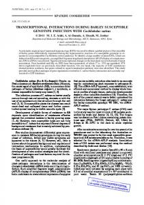
Dislocation/Twin/Interface Interactions during Deformation of PST TiAl Single Crystals, an AFM Study Yali Chen, David P. Pope and Vaclav Vitek Department of Materials Science and Engineering, University of Pennsylvania Philadelphia, PA 19104-6272, U.S.A ABSTRACT PST TiAl crystals oriented such that the deformation axis lies in the (111) interfacial planes have been deformed in compression. This deformation produces so-called "channeled flow" in which the strain perpendicular to the (111) interfaces is zero, while the other two strains are equal and opposite in sign. Thus the sample simply shortens axially and spreads laterally in the channels defined by the (111) interfacial planes. We have examined the fine structure of deformation bands on the free surface of these deformed samples using AFM to see how the deformation processes interact with the boundaries. By measuring the offset angle at the surface we have been able to show that not only is the macroscopic displacement vector parallel to the lamellar boundaries, but the total shear vector in each layer is also parallel to the lamellar boundaries. However these deformation bands have very different characters, requiring complex deformation processes at the boundaries in order to satisfy this requirement. Some consist of either just super dislocations or just ordinary dislocations with Burgers vectors lying in the interface. But others consist of a special combination of twinning and ordinary dislocations in fixed ratio, such that the net shear vector also lies in the boundary, even though the individual twinning and dislocation shear directions are inclined to it. This results in deformation that is homogeneous and completely ‘channeled’ inside each lamella with no shear vector perpendicular to the lamellar boundaries. We have also shown that the cooperative twinning and slip is homogeneous on the nano-scale, i.e., the twinning and slip occurs in the same volume of material. INTRODUCTION Two-phase TiAl intermetallic compounds with lamellar structures are promising candidates to serve as high temperature structural materials. A great deal of effort has been made to improve the toughness and ductility of TiAl materials [1, 2]. The deformation behavior of this material also has attracted a a great deal of attention, but it is difficult to study the deformation mechanisms in random polycrystals due to the complexity of the interfaces. Polysynthetically twinned (PST) crystals, on the other hand, are especially good candidates for studying the interaction of slip and twinning systems with boundaries [3-5] because the lamellar boundaries appear to dramatically control the gross deformation behavior of the crystal. The microstructure of PST crystals is illustrated in figure 1. The two phases, α2-Ti3Al and γTiAl are ordered in such a way that the (0001) plane of the α2 phase is parallel to the {111} planes of the γ phase and the < 1120 > directions of the α2 phase are parallel to the < 110 > directions of the γ phase. Because of the slight tetragonality of the γ phase, one of the < 110 > directions is not equivalent to the other two on the same close packed plane. As a result, there are six possible ways to fulfill the crystallographic relationships between the two phases, and thus, the γ phase is ordered as six domains in each γ lamella.
BB3.10.2
γ -TiAl
Domain boundary
domain
γ-TiAl γ/γ lamellar boundary α2-Ti3Al γ/α2 lamellar Boundary
Figure 1. Schematic of the PST crystal microstructure (The normal to the lamellar boundaries is parallel to the [0001] direction of the α2 phase) This special structure leads to a markedly anisotropic deformation behavior [3-5]. When the loading axis is parallel (A orientation) or perpendicular (N orientation) to the lamellar boundaries, the material is plastically hard, but when the loading axis is inclined to the lamellar boundaries, it is relatively soft. The anisotropic deformation behavior can also be seen in the sample shape after deformation [4] and in the results of precise measurements with micro strain gages [5]. It was first shown from shape changes [4] that the strain perpendicular to the lamellar boundaries is zero in A oriented samples, i.e., the plastic deformation results in a state of plane strain. In order for this to happen, the net shear vector in each lamella must be parallel to the lamellar boundaries. Is the local shear vector parallel to the lamellar boundaries at all scales of observation, or just on the macro level? TEM studies have shown that the post-deformation lamellar boundaries are still quite straight, so it appears that the deformation is confined within each lamella at this level of observation. TEM observations have also revealed that twinning and ordinary dislocation slip are the easiest deformation modes in the γ phase of PST crystals. But because the twinning vector is always inclined to the lamellar boundaries, it must be combined with another deformation mode in order to make the net shear lie in the lamellar plane. In this case the twinning is combined with ordinary dislocation slip in order to cancel the shear along the [111] direction. What’s more, if twinning and ordinary dislocation slip occur at different places within a given domain, then the strain perpendicular to the lamellar interfaces is not exactly zero everywhere. So, we propose a new deformation mode in the γ phase in which the twinning and ordinary dislocation slip occur in the same place and at the same time, i.e., the dislocations and twins move at the same speed within the same volume of material. More specifically, when part of the material shears by the requisite amount along the twinning vector on three continuous atomic planes, it will also shear along the Burgers vector of the ordinary dislocation on the third plane, thereby canceling the strain along [111], as illustrated in figure 2. This new mode has similar contrast as that of pure twinning under TEM. But when this deformation mode reaches a free surface, different offsets will be produced and they can be distinguished from each other by advanced surface characterization techniques. Atomic force microscopy (AFM) was used in this research to study the local surface offsets of deformed A oriented samples. The fine structure of the deformation bands was accessed three dimensionally and the angular offsets were measured to identify the new deformation mode.
BB3.10.3
3bT
3bT
bO.D.
bNET
bNET
bO.D.
Slip plane
Figure 2. Illustration of ‘channeled deformation’ in one lamella. The shear vectors for twinning (bT) and ordinary dislocations (bO.D.) are both inclined with the lamellar interfaces, but the sum of the two is parallel to the lamellar interfaces. EXPERIMENTAL DETAILS PST crystals with a nominal composition of 52 at% Ti and 48 at% Al were grown using an optical floating zone furnace. A1 samples, see figure 3, 3×3×6mm, were cut from the crystals, mechanically polished, and then electro-polished. Compression tests were performed at room temperature at an average strain rate of 2×10⁻⁴/s. The loading axis is parallel to the lamellar boundaries. AFM measurements were made using a DI “dimension 3000” AFM at the tapping mode, as used by Lu et al for B-oriented samples [6]. The scanned surface is perpendicular to the lamellar interfaces and the scan direction is parallel to the lamellar interfaces as that shown in figure 3. Both height images and amplitude images were recorded. The amplitude image records the derivative of the surface height along the scan direction. It is the more sensitive of the two modes and was used here to study the general features of the deformation traces. The height images were used to measure the width, height and angle of the offsets. The offset angle is taken to be the acute angle between the line of the scan trace on the undeformed surface and that on deformation band. The calculated value of the offset angle for pure twinning is 30°, and that for the new mode, twinning mixed with ordinary dislocations (3bT+bO.D.), is 41° in A1- oriented samples. All other deformation modes produce bands with arbitrary angles.
Scan direction
Indices in six γ domains
Scan surface
X Z
Y
Domain IM IT IIM IIT IIIM IIIT
X
Y
110 110
112 112
101
121
101
121
011
211
011
211
Figure 3. Geometry of the A1 orientation samples under compression and during AFM observation. The Z axis is parallel to the [111] direction in all lamellae.
BB3.10.4
The minimum width of a band having a constant 30° offset angle that can be resolved using a probe with a 10 nm radius tip is 3nm. Consequently we conclude that the minimum homogeneous band we can reliably resolve is approximately 20nm, or about 10 {111} planes thick. If a band is thinner than 20nm, or if it is thicker but discontinuous, then the measured offset angle will be less than 30°. RESULTS The morphology of two deformed samples is shown in figure 4. When the sample experiences a small plastic deformation (~2%), the deformation traces are relatively far from each other and each of the bands goes across nearly all the lamellae in one sample (a). When the deformation increases (~5%), the deformation bands become dense (b). It can be seen that most of the traces have a bright color, which corresponds to the situation in which the surface height increases along the scan direction. These traces are termed as ‘uphill bands’. ‘Downhill bands’ (with a darker color) were also found, in which the surface height decreases along the scan direction. However, these bands occur very infrequently and usually disappear after going across just a few layers, as shown in figure 4(b). Uphill and downhill bands are sometimes seen within the same γ domain and represent deformation on two symmetric slip planes, but such symmetric slip modes have not been observed in TEM studies because of the small volumes that can be observed [4]. Since AFM can examine a much larger area, it provides new information about the deformation modes occurring on a more macro scale. What’s more, AFM samples are much easier to prepare and they maintain the original deformation structures after unloading. The traces inclined with the lamellar interfaces represent different deformation systems in the different γ domains. As is known from the work of Kishida, et al [5], some of them are produced by slip of just ordinary dislocations or just super dislocations with Burgers vectors parallel to the lamellar boundaries, and some of them are the traces of twinning plus ordinary dislocation slip. The vertical traces (traces perpendicular to the lamellar boundaries) represent prismatic slip in the α2 lamellae. The offset angles of uphill bands measured after 2% and 5% axial strain are shown in figure 5. Only pure twinning or the special twinning-plus-ordinarydislocation mode (3bT+bO.D.) will produce offsets on the surface at specific angles, about 30° for the former and 41° for the latter case. Neither of these two peaks is seen in figure 5 for either level of deformation, but many bands with angles approaching 40° are seen after 5% deformation. We currently believe that the peak seen at about 20° after 2% deformation is a statistical artifact, but the growing peak seen near 40° after 5% deformation is evidence for an increasing number of sufficiently wide twinning-plus-ordinary-dislocation bands. Lu et al [6] had no difficulty resolving pure twin bands in B-oriented samples, because many relatively thick bands could be found in those samples. This is because those bands run across the broad dimension (about 100 µm) of the pancake-shaped lamellae, but in the present case the twins run across the narrow dimension (about 1 µm). As a result, these shorter bands are also very thin, to the point of being unresolvable until axial strains approaching 5% are reached. Axial deformations greater than 5% are planned for the next series of experiments in an attempt to check this hypothesis. Also, using probes with ultra-fine tips can reduce the resolution limit. Other surface techniques which can provide orientation information, such as Orientation Imaging Microscopy, will be very helpful in uniquely associating the deformation modes with the orientation in each domain.
BB3.10.5
Scan direction
(a)
(b)
Figure 4. Amplitude images showing the morphology of the deformation traces on the free surface: (a) Uphill bands (lines with bright color) in the sample deformed by 2%; (b) Uphill bands and a few downhill bands (lines with dark color) in the sample deformed by 5%;
0.25
2% deformation
5% deformation
Frequency
0.2
0.15
0.1
0.05
0
0
4
8
12
16
20
24
28
32
36
40
Range of offset angles (degree)
Figure 5. The offset angle distribution in samples with two amounts of deformation Because the shear vector is always parallel to the lamellar boundaries, the deformation is channeled in each lamella, thereby assuring local strain compatibility across every lamellar interface. Compatibility across the interface is accomplished by allowing an arbitrary shear vector parallel to the interface but no shear perpendicular to it. As a result, the offsets measured on the free surface within one deformation band is constant across many lamellae, even though the deformation systems change from lamella to lamella. Furthermore, if a given deformation band is comprised of a number of coarse bands with large offset angles in one lamella and fine bands with low offset angles in an adjacent lamella, then far more of the latter are seen so as to maintain compatibility across the interface, as is shown in figure 6.
BB3.10.6
Figure 6. Surface plot illustrating the strain compatibility across a lamellar interface CONCLUSIONS Deformation traces can be clearly imaged on the free surface of PST TiAl crystal samples compressed parallel to the lamellar boundaries. The distribution of deformation traces on the free surface is heterogeneous, but the total slip across one band is constant from one end of the band to the other. Also, the total slip vector in one band always lies in the lamellar planes, thereby producing ‘channeled’ flow. The distribution of micro slip traces within a given band is also heterogeneous (but the net slip due to all the micro slip traces within a given band is constant along the length of the band). A new deformation mode, consisting of twinning plus ordinary dislocation slip within a given band was found to be operative in samples having this orientation, but these bands could only be resolved in samples deformed at least 5%. ACKNOWLEDGEMENT The authors gratefully acknowledge the National Science Foundation for supporting this work. REFERENCES 1. F. Appel and R. Wagner, Mater. Sci. & Eng. R, 22, 187 (1998). 2. Y. W. Kim, Intermetallics, 6, 623, (1998). 3. T. Fujiwara A. Nakamura, M. Hosomi, S. R. Nishitani, Y. Shirai and M. Yamaguchi, Philos. Mag. A, 61 (4), 591 (1990). 4. K. Kishida, H. Inui and M. Yamaguchi, Philos. Mag. A, 78 (1), 1 (1998). 5. M. Kim, M. Nomura, V. Vitek and Pope D., in High-Temperature-Ordered Intermetallic Alloys VIII, edited by E.P. George, M. Yamaguchi and M.J. Mills, (Mater. Res. Soc. Proc. 552, Boston, MA, 1998) pp KK3.1.1 - KK3.1.6. 6. L. Lu, D. P. Pope in High-Temperature Ordered Intermetallic Alloys VII, edited by C.C. Koch, C.T. Liu, N.S. Stoloff, A. Wanner, (Mater. Res. Soc. Proc. 460, Boston, MA, 1996) pp249.