moda, Festinger, Phillips, Duckman, & Young, 1973). Also, saccadic eye movements in picture or scene per- ception tend to display scan patterns with clusters of ...
Perception & Psychophysics 2001, 63 (1), 1-15
Distance perception mediated through nested contact relations among surfaces JEANETTE C. MENG and H. A. SEDGWICK State University of New York, New York, New York In complex natural scenes, objects at different spatial locations can usually be related to each other through nested contact relations among adjoining surfaces. Our research asks how well human observers, under monocular static viewing conditions, are able to utilize this information in distance perception. We present computer-generated naturalistic scenes of a cube resting on a platform, which is in turn resting on the ground. Observers adjust the location of a marker on the ground to equal the perceived distance of the cube. We find that (1) perceived distance of the cube varies appropriately as the perceived location of contact between the platform and the ground varies; (2) variability increases systematically as the relating surfaces move apart; and (3) certain local edge alignments allow precise propagation of distance information. These results demonstrate considerable efficiency in the mediation of distance perception through nested contact relations among surfaces.
Alhazen (1989, p. 155) proposed that the perception of distance of objects relies on the perception of their relation with a continuous background. J. J. Gibson (1950, p. 6) proposed a similar hypothesis, which he named the ground theory of space perception. These two formulations both emphasized the importance of the underlying background surface, especially the ground plane, in distance perception. Gibson characterized the visual environment of land-dwelling animals, such as ourselves, as terrestrial, meaning that there is generally a continuous, more or less horizontal ground surface on which objects rest and by means of which they are related to one another. He showed that the perceived relative size of objects resting on the ground remains reasonably accurate out to great distances (J. J. Gibson, 1950, pp. 183–186). A substantial amount of research has been done since, concerning perceived size and distance over the ground plane (see reviews by Cutting & Vishton, 1995; Gillam, 1995; Sedgwick, 1986, in press). Most research suggests that our ability to perceive layout and distance is quite good in large, open outdoor spaces, where multiple sources of information are available. There is some foreshortening in matching depth intervals along the sagittal versus the frontal plane (Levin & Haber, 1993; Loomis & Philbeck, 1999; Toye, 1986), although visually cued blindfolded walking shows no foreshortening in distance up to at least
12 m (Loomis, Da Silva, Fujita, & Fukusima, 1992; Loomis, Da Silva, Philbeck, & Fukusima, 1996; Thomson, 1983). Recently, Sinai, Ooi, and He (1998) reported an experiment in which they tested the importance of continuity of the ground plane. They found that both perceptual judgments of absolute distance and visually cued blindfolded walking are compromised when a gap or texture discontinuity is present on the ground. They concluded that error is introduced when the reference frame provided by the common ground surface is disrupted. Sinai et al.’s (1998) results are particularly interesting because in our everyday environment we routinely encounter spatial arrangements that are far more complicated than those in their experimental conditions. In fact, it is a rather rare situation where everything rests on an undisrupted common ground surface. If we look around a room, for example, most of the objects do not share a common surface. They could be on the windowsill, on the table, in the bookshelf, or piled on top of each other on the floor. They could also be suspended on the wall or from the ceiling. Nevertheless, apart from floating or flying objects, everything in our environment is ultimately supported by the ground. Perhaps a cup is resting on the table, and a book is resting on the bookshelf, but both the table and the bookshelves are resting on a common floor. Thus the cup and the book can theoretically be related to each other through a series of contact relations between adjoining surfaces. We refer to “nested” contact relations to indicate that there are many levels of relation, with a certain degree of hierarchical organization, among objects on different surfaces. The ability to perceive these relations then becomes essential if we are to establish and utilize a common reference frame through which egocentric or exocentric distance perception takes place.
This work was supported by a grant from the Schnurmacher Institute for Vision Research. Portions of this work were presented at the 1998 and 1999 meetings of the Association for Research in Vision and Ophthalmology, Fort Lauderdale, Florida. We thank Andrea Li and two anonymous reviewers for helpful comments on earlier versions of this paper. Correspondence should be addressed to H. A. Sedgwick, Vision Science Department, State University of New York, State College of Optometry, 33 West 42nd Street, New York, NY 10036 (e-mail: sedgwick@ sunyopt.edu).
1
Copyright 2001 Psychonomic Society, Inc.
2
MENG AND SEDGWICK
Sedgwick (1983; Sedgwick & Levy, 1985) has developed an environment-centered description of complex spatial layouts in which the locations of surfaces are specified in relation to the ground plane. For surfaces that are not directly in contact with the ground, location information is specified first by local contact relations with adjacent surfaces. This location information then propagates through a series of contact relations that ultimately link each surface to the ground plane and hence to other surfaces in the environment. Using a simplified environment of planar polygonal surfaces, Sedgwick (1987a, 1987b, 1989) modeled a subset of the optic array information available from perspective and optical contact and showed that it was sufficient in most cases to recover the three-dimensional (3-D) spatial layout of the environment. Sedgwick (1989) reported a preliminary experiment on the interaction of perspective information and optical contact in determining perceived contact. As far as we are aware, however, there has been no other em-
pirical work done, prior to that reported here, to explore the ability of human observers to make use of nested contact relations in the perception of spatial layout. Here we describe four experiments that initiate such an exploration. We started with a very basic situation: A cube is resting on a platform, which in turn is perceived to be resting on the ground (Figure 1). In our first experiment, we asked how the perceived distance of the cube changes if the perceived location where the platform contacts the ground changes. To do this, we manipulated what J. J. Gibson (1950) called the “optical contact” between the platform and the ground. J. J. Gibson (p. 174) demonstrated a compelling effect of perceiving an object, secretly suspended in midair, to be resting on the ground at a more distant location, where the line of sight through the bottom of the object met the ground. Using the same strategy in a virtual environment, we suspended the platform above the ground, so that the distance of its optical contact with the ground was greater than its actual, or “geo-
Figure 1. The four conditions in Experiment 1 show a cube resting on a block of varying thickness. The top slabs in all four scenes are held at 64 cm above the ground. (a) The block is made up of four slabs, with a total thickness of 64 cm, and is resting on the ground. (b) The block is made up of three slabs, with a total thickness of 48 cm, and is suspended 16 cm above the ground. (c) The block is made up of two slabs, with a total thickness of 32 cm, and is suspended 32 cm above the ground. (d) The block is made up of one slab, with a total thickness of 16 cm, and is suspended 48 cm above the ground. (Original displays were in color.)
DISTANCE PERCEPTION THROUGH SURFACE CONTACT RELATIONS
3
Figure 2. In Experiment 1, a block suspended in midair is seen resting on the ground at a greater distance. The distance from the eye to the cube in a straight line through space is referred to as the absolute distance. The cube’s true distance along the ground is referred to as its geographic distance. The cube’s optically specif ied distance, mediated by the block, is referred to as its mediated distance. If the block were absent or ignored, the cube would be seen resting on the ground at an even greater distance, specified by its optical contact with the ground. (This illustration is not drawn to scale.)
graphic” distance from the observers (Figure 2). We kept the top surface of the platform at a constant height but varied its thickness beneath, so that the bottom of the platform was suspended at various heights above the ground. In this way, we were able to hold the cube’s absolute and geographic distance and height constant so that any changes in its perceived distance would be due entirely to the effects of varying the perceived optical contact between the bottom of the platform and the ground. EXPERIMENT 1 Method
We used the 3-D Studio Max software package (by Kinetix) to generate 3-D scenes. Objects were modeled in virtual 3-D space and rendered with photo-realistic textures. Images were pregenerated and stored on the hard drive. During the experiment, images were displayed on a 21-in. monitor with a pixel resolution of 1,024 3 768. A Windows NT program created with the PiXCL language (by Vysor Integration) controlled the sequencing and displaying of images and the gathering and storage of data. Displays were viewed monocularly in the dark using the dominant eye. The observer’s head was held steady by a chin and forehead rest. The perspective view simulated that of a 35-mm camera with a 50-mm (“normal”) lens. The eye was aligned to be at the correct viewing position, which was 14.0 cm above the bottom of the monitor screen and 52.1 cm from the monitor screen. The total eye height above the floor was 118 cm. The whole scene subtended 39.5º horizontally and 30.1º vertically. A hood hid the edges of the monitor as well as the rest of the room. The dimensions of all the scene parameters and the measured responses given in this paper are scaled according to an arbitrarily as-
sumed camera height of 140 cm above the ground plane in the virtual space. There is no information in the virtual space, though, to specify this scale factor. Therefore, the perceived scale of the scene may have been different. Since we asked our observers to make judgments of relative distance within the virtual space, variation in the perceived scale of the scene should not affect our results. Each scene consisted of a textured ground extending to the horizon, with a large green marble block (made up of one to four slabs, each 1,600 cm long 3 150 cm wide 3 16 cm high) serving as the platform for a small limestone cube (40 3 40 3 40 cm; Figure 1). On the ground, 1 m to the right of the block platform, was a parallel track (20 cm wide) extending to a distance of 560 m. Locations on the ground are specif ied by distance from the observer in the virtual space of the scene. To illustrate the ground location of an object at some elevation above the ground, the experimenter used the tabletop as the hypothetical ground, and moved a pencil back and forth to the location directly beneath the front edge of a small object resting on a platform 10 cm above the tabletop. We were careful not to suggest any strategy in performing the task. Observers were encouraged to think of the display as representing a real 3-D scene in which they could walk along the track on the ground to where they perceived the front edge of the cube to be. At the beginning of each trial, a cursor in the form of a horizontal double arrow appeared on the screen at either the near or far end of the track. Observers were instructed to use the computer mouse to move the arrow to the position on the track that matched the perceived distance of the front edge of the small cube. They were instructed to bracket their settings by moving the arrow back and forth starting from locations that were obviously too far or too close; they were allowed to take as much time as they needed. When the setting was complete, the observer clicked the mouse button, and the arrow position was recorded. Although the program left the cursor arrow free to move to any position on the screen, observers were instructed
4
MENG AND SEDGWICK
to keep the arrow on the track, and were monitored to ensure that they did so. The program ignored any mouse clicks that occurred when the arrow was not on the track. Although the track was depicted as receding in depth, the cursor arrow did not change its image size as it moved up and down along the track. We held the top surface of the block at a constant height (64 cm) above the ground, but varied the thickness of the block (below its top surface) by adding or subtracting additional slabs beneath the top one. At its greatest thickness (made from four slabs, Figure 1a), the bottom of the block rested on the ground. At the other thicknesses, however, the block floated above the ground, so that the projected optical contact of its bottom front edge with the ground was at a greater distance than its actual geographic distance (Figure 2). Although the block was located at a specific geographic distance and floated at a specific height above the ground in our computer model of the virtual scene, in the monocular projection of this scene that was viewed by our observers there was no information to specify whether the block was floating above the ground or resting on the ground at a greater distance. Cast shadows can provide effective perceptual information that something is floating above the ground rather than resting on it (Kersten, Mamassian, & Knill, 1997; Madison & Kersten, 1999; Yonas, Goldsmith, & Hallstrom, 1978). For the purpose of this experiment, however, shadows were eliminated. Although our scenes were thus geometrically ambiguous, our observers perceived the block as resting on the ground. No observer reported seeing the block as floating, and as the results presented below clearly show, our observers’ distance settings were entirely consistent with the perception that the block was resting on the ground. The effect of holding the height and geographic distance of the cube constant was to ensure that any change across conditions in the observers’ distance settings must be due to the change in the block’s optical contact with the ground. Thus the design of Experiment 1 allowed us to isolate and measure the effectiveness with which the
perceived position of the block can mediate the perceived distance of the cube resting on top of it. The cube’s position relative to the block was held constant throughout the experiment, with the separation between the cube’s and the block’s front and right edges at 380 and 85 cm, respectively. Thus, as the thickness of the block varied, any change in the perceived distance of the cube must have been mediated by the perceived contact relation between the block and the ground. At each thickness of the block, we also varied the position of the block and cube together. This was done to prevent observers from remembering and replicating their previous settings. Sixteen distances along the ground were used at 20-cm increments, with the geographic distance of the cube starting at 9.41 m from the observer. We also varied the pattern of texture on the ground and on the block from trial to trial, so that the observers were not able to use textural landmarks to recognize their previous settings. For each scene, observers made both an ascending and a descending adjustment, with the arrow starting either at the near or the far end of the track, respectively. The combination of height (4) 3 distance (16) 3 starting position (2) gave rise to 128 trials, which were presented in a random order. Eight observers participated, including the two authors. All had 20/20 corrected vision with their dominant eye. Apart from the authors, the other observers were naive as to the purpose of the experiment.
Results The means, with 95% confidence intervals across observers, of matched distance of the cube for each thickness of the block are plotted in Figure 3a. Since the mean results for ascending and descending trials are very similar, they were pooled. Each bar in the figure thus repre-
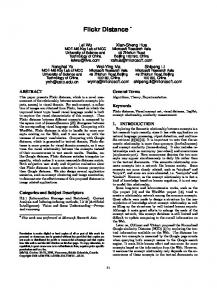
Figure 3. Results from Experiment 1. (a) Means, with 95% confidence intervals across observers, of matched distance of the cube at each block thickness. The number on the abscissa refers to the number of slabs used for that particular thickness. The solid line across each column marks the predicted mediated distance of the cube at each block thickness. The upper dotted line marks the cube’s optically specified distance if the block were absent or ignored. The lower dashed line marks the cube’s geographic distance. (b) Means, with 95% confidence intervals, of the r 2 values from 8 observers.
DISTANCE PERCEPTION THROUGH SURFACE CONTACT RELATIONS sents an average of ascending and descending trials over 16 distances on the ground for all 8 observers (256 trials per bar). The lower dashed line marks the average geographic distance of the cube, which remained constant at 10.91 m across conditions. The horizontal solid line on each bar marks the predicted distance of the cube, as mediated by the optical contact of the block with the ground—a value that we shall henceforth refer to simply as mediated distance. For block thickness of one to four slabs, the mean predicted mediated distances are 16.59, 14.13, 12.32, and 10.91 m, respectively. The corresponding mean matched distances are 17.39, 15.65, 14.02, and 12.9 m. The decrease in matched distance with increasing thickness of the block is significant according to a two-way within-subjects repeated measures analysis of variance (ANOVA) [F(3,21) 5 109.7, p < .000001]. It is clear that the average perceived ground location of the cube corresponds reasonably well with specified ground location, mediated through the block. The upper dotted line in Figure 3a marks the cube’s optically specified distance at 20.07 m if the block were absent or ignored, in which case the cube would be seen directly resting on the ground, but further away (illustrated in Figure 2). There appears to be some tendency for matched distance to be biased in this direction, although, except for the four-block condition, the theoretically correct value falls within the 95% confidence interval. This bias suggests that even though our observers were able to perceive the cube’s distance through its contact relation with the block, and in turn with the ground, they may have had a weak tendency to relate the cube directly to the ground. This would have resulted in the observed overestimation relative to the predicted mediated distance. It is also possible that this overestimation reflects a tendency simply to set the marker at the same height in the picture plane as the cube. In order to assess the variability of our observers’ performance, a linear regression line was f itted for each observer over 16 distances, and r 2 (squared correlation coefficient) values were calculated to indicate the percentage of variability accounted for. Figure 3b shows the means, with 95% confidence intervals, of the r 2 values at each thickness of the block over 8 observers. As the thickness of the block increases, performance variability increases, as reflected in the decrease in r 2. The one-way ANOVA (within-subjects repeated measures design) of the mean r 2 is significant for the four conditions [F(3,21) 5 5.284, p < .01]. This result shows that as the relating surfaces (the ground and the top surface of the block) move apart, precision of performance decreases. Experiment 2 was designed as a control for two purposes. The first was to vary the height of the cube in the image plane without varying its mediated distance simultaneously. The second was to investigate whether increasing the cube’s height above the ground leads to overestimation of distance. As a baseline, an extra condition was added, in which the block was absent, and the cube was directly resting on the ground by itself.
5
EXPERIMENT 2 Method
The viewing arrangement and method of adjustment were the same as in Experiment 1. The scenes were the same as in Experiment 1, except that the block was always resting on the ground. The thickness or height of the block was increased by adding a slab on top of the previous one, thus raising the height of the cube above the ground. Therefore, the mediated distance of the cube equaled its geographic distance in all the conditions. As the height of the block changed, any systematic change in the perceived distance of the cube must thus be due either to the cube’s changing height in the image plane, or, equivalently, to a perceptual tendency to relate the cube directly to the ground. Five conditions were used: the cube on the ground by itself and the cube resting on a block made up of one, two, three, and four slabs. The corresponding block heights were 0, 16, 32, 48, and 64 cm. Again, the cube’s position relative to the block was held constant throughout the experiment. For each condition, 16 distances along the ground were used at 20-cm increments, with the cube’s geographic distance starting at 9.41 m from the observer. Texture elements were varied from trial to trial. The combination of height (5) 3 distance (16) 3 starting position (2) gave rise to 160 trials, which were presented in a random order. Eight observers participated; 3 of them, including the two authors, also participated in Experiment 1. All had 20/20 corrected vision with their dominant eye.
Results The means, with 95% confidence intervals across observers, of matched distance of the cube at each block height are plotted in Figure 4a. Each bar represents an average of ascending and descending trials over 16 distances on the ground for all 8 observers (256 trials per bar). The dashed line marks the cube’s averaged mediated distance on the ground, which is 10.91 m and equals the actual geographic distance in all five conditions. The means for matched distance are all in good agreement with the mediated and geographic distance. There is no overestimation observed in this experiment. The dotted line on top of each column marks the cube’s optically specified distance if the block were absent or ignored, in which case the cube would be seen resting on the ground at a greater distance. This distance varies as a function of the cube’s image height in the picture plane. Observers were clearly not relating the cube directly to the ground, since the overall means remain close to the predicted mediated distance in all conditions. The same statistical method used in Experiment 1 was employed to assess performance variability. Figure 4b shows the means, with 95% confidence intervals, of the r 2 values at each block height over 8 observers. The increase in performance variability versus block height was significant [F(4,28) 5 14.928, p < .000001]. As in Experiment 1, as the surface on which the cube rested was raised higher above the ground, precision of performance deteriorated. DISCUSSIO N OF EXPERIMENTS 1 AND 2 Our results show that observers’ relative distance perception is in good agreement with the mediated distance of the cube. Since the cube’s actual geographic distance
6
MENG AND SEDGWICK
Figure 4. Results from Experiment 2. (a) Means, with 95% confidence intervals across observers, of matched distance of the cube at each block height. The number on the abscissa refers to the number of slabs used for that particular height. "0" stands for the ground condition, where the block is absent and the cube rests on the ground. The lower dashed line marks the cube’s geographic distance, which equals its mediated distance. The dotted line on top of each column marks the cube’s optically specified distance if the block were absent or ignored. (b) Means, with 95% confidence intervals, of the r 2 values from 8 observers.
was held constant, any perceived changes were due to the perceived change of location of contact between the block and the ground. This demonstrates that perceived distance could indeed be effectively mediated through a series of nested contact relations among surfaces, as suggested by Sedgwick (1989). Madison and Kersten (1999) have demonstrated that, without cast shadows or interreflection, observers were not able to tell the difference between an object that was resting on the ground and an object that was floating above the ground. Under monocular static viewing conditions, optical contact with the ground plane tends to be perceived as physical contact when all other pictorial cues that could specify lack of contact, such as cast shadows, are absent (J. J. Gibson, 1950, p. 174). The close agreement between perceived and mediated distance in Experiments 1 and 2 further confirmed this tendency. If the block had been perceived floating above the ground, it should also have been perceived as closer (Figure 2). Such systematic underestimation of distance was not observed in any condition. In order to establish a common reference frame, observers need to relate relevant surfaces across a certain amount of distance. We found that performance variability increases significantly as the relating surfaces move apart from each other. Following this observation, in Experiment 3 we explored how different positions on the platform’s surface affect the propagation of distance in-
formation among surfaces. We held the distance between the relating surfaces constant but varied the cube’s location relative to the front and lateral edges of the block’s top surface. EXPERIMENT 3 Method
The viewing conditions remained the same as in the previous experiments. A block, 64 cm in height, served as the platform for the cube. The cube’s relative position varied with respect to the front and right edge of the block’s top surface (Figure 5). The cube had three positions with respect to the block’s right edge: left, where there was a separation of 85 cm between the right edges of the cube and the block; center, where the separation was 42.5 cm; and right, where the two right edges were lined up. The cube also had three positions with respect to the front edge of the block: near, where the cube’s and block’s front edges were aligned; intermediate, where the cube’s position was held constant, and the block was slid underneath toward the observer, so as to create a separation of 190 cm between their front edges; and far, where the block was slid further toward the observer to create a separation of 380 cm. Because the position of the cube relative to the front edge of the block was varied by moving the block, the cube’s geographic and mediated distance remained the same across conditions. We also included a condition labeled as ground, in which the block was absent and the cube rested directly on the ground. In the ground condition, the cube had the same geographic distance and the same three lateral positions as in the conditions with the block. For each condition, the distance of the cube and the block together was also varied. Eight distances
DISTANCE PERCEPTION THROUGH SURFACE CONTACT RELATIONS
7
mediated by the block. The means for matched distances in all conditions are very close to the mediated distances in the 3-D scenes. We looked at the observers’ performance variability by fitting regression lines to each observer’s data, as in Experiments 1 and 2. The means, with 95% confidence intervals, of the r 2 values are plotted for each condition in Figure 6b. When the cube is resting on the ground by itself (ground condition), or when its front edge is lined up with the block (near condition), performance variability is very low (average r 2 5 .98). As the separation between the front edges of the cube and the block increases (intermediate and far conditions), variability also increases (average r 2s 5 .78 and .72). The result of an ANOVA confirmed the significance of the increase due to separation in depth [F(3,21) 5 18.19 , p < .00001]. Lateral separation (left, center, and right conditions) had no significant effect.
Figure 5. The nine positions of the cube, with respect to the block’s top surface, used in Experiment 3. Note that for the near to far displacements the cube remained at the same geographic distance, while the block was displaced under it toward the observer. (This illustration is not drawn to scale.)
were used with 40-cm increments in depth, with the geographic distance of the cube starting at 9.61 m from the observer. The observer’s basic task remained the same, which was to adjust the location of a marker on the ground to match the perceived distance of the cube’s front edge. To test whether a more realistic appearance of the marker would have an effect on observers’ performance, we changed the marker to a horizontal thin red line moved by pressing the “Up” and “Down” arrow keys on the keyboard. The red line was seen as resting on the track, and changed its width as it moved according to the correct perspective in the virtual space. In the previous experiments, the horizontal arrow did not change image size as it moved. The combination of distance of the cube (8) 3 position of the cube on the block’s top surface, including the ground condition, (12) 3 starting position (2) gave rise to 192 trials, which were presented in a random order. Texture was varied in each scene to eliminate the possibility of tracking landmarks. Eight observers participated, including the two authors and six naive recruits. All had 20/20 corrected vision in their dominant eye.
Results Figure 6a shows the means, with 95% confidence intervals across observers, of the cube’s matched distance, arranged according to each location of the cube with respect to the block. Each bar represents an average of ascending and descending trials over eight distances on the ground for all 8 observers (128 trials). The lower dashed line marks the cube’s average geographic distance across conditions (11.01 m), which equals the average distance
Discussion Precision of performance when the front edges of the cube and the block were aligned was as good as when the cube was directly resting on the ground. Because of this alignment, the cube’s ground location was effectively replaced by the block’s location on the ground. As soon as the cube moved away from the block’s front edge, performance variability increased significantly. Lateral separation, within our range of variation, had no effect on performance; in particular, alignment of the right edges of the cube and the block did not increase precision. In Experiments 1 and 2, observers’ settings were made with a horizontal arrow whose image size did not change as it moved up and down the track. In this experiment, settings were made with a horizontal line segment whose image size changed appropriately as it moved along the track. We see no indication that the more realistic looking marker used in this experiment made any difference in the observer’s settings. In particular, the display in the far-left condition in this experiment was almost identical to the four-slab condition in Experiment 2. Comparison of the results for these two conditions indicates that the corresponding means of matched distance across observers are 11.1 and 10.47 m with the predicted values at 10.91 and 11.01 m, respectively. The average precision, measured by r 2, is .74 in both conditions. In the experiments reported thus far, the platform in all the scenes consisted of a single rectangular block. There was only one step linking the cube to the ground, even though the height of the step varied from trial to trial. In the following experiment, while holding the height of the platform constant, we varied the complexity and proximity of the information linking the cube’s position to the ground. EXPERIMENT 4 Method
The viewing arrangement and method of adjustment were the same as in Experiments 1 and 2.
8
MENG AND SEDGWICK
Figure 6. Results from Experiment 3. (a) Means, with 95% confidence intervals across observers, of matched distance of the cube, arranged according to the cube’s location relative to the top surface of the block. The lower dashed line marks the cube’s geographic distance, which equals its mediated distance. The upper dotted line marks the cube’s optically specified distance if the block were absent or ignored. (b) Means, with 95% confidence intervals, of the r 2 values from eight observers.
Four kinds of platform were used. All of them were resting on the ground with realistic shadows, and all had the same height of 64 cm. They were a block (Figure 7a), as in Experiment 1; a staircase (Figure 7b), in which we increased complexity by introducing multiple steps linking the cube to the ground; a table (Figure 7c), in which the only height information linking the cube to the ground was provided by the table’s front and back legs; and finally, a complex platform combining the features of the staircase and the table (Figure 7d). The cube’s position relative to the platform was held constant throughout the experiment, and was the same as in Experiments 1 and 2. For each platform, 16 distances were used along the ground at 20-cm increments, with the cube’s geographic distance starting at 9.41 m from the observer. The combination of the type of the platform (4) 3 distance (16) 3 starting position (2) gave rise to 128 trials, which were presented in a random order. Texture was varied as before. The same 8 observers participated as in Experiment 1, including the two authors.
Results The means, with 95% confidence intervals across observers, of matched distance of the cube for each type of platform are plotted in Figure 8a. Each bar represents an average of ascending and descending trials over 16 distances on the ground for all 8 observers (256 trials per bar). Our observers’ settings are in good agreement with the actual geographic distance of the cube. Performance variability was assessed via the same statistical methods used previously. Figure 8b is a plot of the means, with 95% confidence intervals, of the r 2 values over 8 observers. No statistically significant differences were found among the different types of platforms used [F(3,21) 5 .45, p < .72]. We conclude that perceptual performance
is unaffected by the variations of complexity and proximity tested here. GENERAL DISCUSSIO N Our research supports the proposal by Alhazen (1989) and J. J. Gibson (1950) that the ground plane can be used as a reference frame for specifying the location of objects. We have applied the “ground theory,” however, to objects that do not rest on the ground or share a continuous background surface. We hypothesized that in these situations, the perceived distance of an object can be mediated through nested contact relations among surfaces. The idea that the perceived distance of “A” is mediated by “B” implies that changing “B” alone changes the perceived distance of “A.” In our experiments, a cube rested on a platform, which in turn, was perceived to be resting on the ground. The results of Experiment 1 demonstrated that the perceived distance of the cube indeed varied appropriately as the optical contact between the platform and the ground varied. What is the information that enables observers to relate the cube to the marker on the ground? It may be helpful to start by considering the simplest condition, when the cube is resting directly on the ground. In this case, setting the marker to the same distance as the front edge of the cube can be done by simply aligning the horizontal marker with the horizontal contour of the cube’s front edge.1 Thus, it is unnecessary to compare the perceived absolute distances of the cube and the marker. The alignment
DISTANCE PERCEPTION THROUGH SURFACE CONTACT RELATIONS
9
Figure 7. The four conditions in Experiment 4 show a cube resting on different kinds of platform with realistic cast shadows. (a) A block, same as in Figure 1a. (b) A stair. (c) A table. (d) Combination of a stair and a table. (Original displays were in color.)
of horizontal contours is a shortcut that permits relative distance to be perceived with considerable accuracy. Our observers’ settings in this condition have a precision that approaches the limit of sensitivity of our measurements. When the cube is elevated above the ground by the platform, to simply align the marker with the cube’s front edge would be equivalent to ignoring the block and treating the cube as though it were resting directly on the ground (Figure 2). Our results (Figures 3a, 4a, 6a, and 8a) indicate that this clearly did not occur; otherwise large overestimation of distance would have been observed. In Experiments 1 and 4, there was only a small amount of overestimation on average, and in Experiments 2 and 3, there was none at all on average. Although some of our observers did show more overestimation than others, particularly in Experiments 1 and 4, none showed an amount or pattern of overestimation that would be consistent with aligning the horizontal contours of the marker and the cube.
Without claiming to be exhaustive, we can think of several possible ways to link the front edge of the cube to the marker on the ground (Figure 9). First, the location of the block can be determined simply by extrapolating the front edge of the block (CD) until it meets the track (at N). From that extrapolated location, the marker could be set at a distance (NM) equal to the perceived distance from the front edge of the platform to the front edge of the cube (BA). This can be expressed symbolically as CD ® N, NM 5
BA.
(1)
Since the platform is raised above the ground, the depth interval BA is more compressed in the optic array than the corresponding depth interval NM along the track. Loomis and Philbeck (1999) have shown that the underestimation of distance is directly related to the amount of compression produced by the ratio of eye height to distance, so it might be expected that the depth interval BA would be perceptually underestimated relative to the depth interval
10
MENG AND SEDGWICK
Figure 8. Results from Experiment 4. (a) Means, with 95% confidence intervals across observers, of matched distance of the cube. The abscissa indicates the type of platform used. The lower dashed line marks the cube’s geographic distance, which equals its mediated distance. The upper dotted line marks the cube’s optically specif ied distance if the block were absent or ignored. (b) Means, with 95% confidence intervals, of the r 2 values from 8 observers.
NM. If so, the marker would need to be set closer than the correct location to make the perceived interval NM equal to the more perceptually compressed interval BA. The higher the platform, the closer the marker would be set. If our observers were matching the two depth intervals described above, each of our four experiments should have shown underestimation across all conditions. None of our
Figure 9. A schematic drawing of the scenes used in the experiments, showing several alternate ways of linking the cube’s distance to that of the marker on the ground. (This illustration is not drawn to scale.)
average results show underestimation. Individual data from Experiments 1 and 4 indicate that the general trend was toward overestimation. In both experiments, 1 observer showed consistent slight underestimation, which, however, could have resulted from random variation in the population. In Experiment 2, matching the depth intervals NM and BA should have produced a pattern of increasing underestimation with increasing block height. The matched distance settings for each of our 8 observers in Experiment 2 are shown in Figure 10a. Note that the vertical scale is magnified to make differences in overor underestimation more clearly visible. The horizontal dashed line marks the average correct settings (10.91 m), which are the same across all five conditions. The heavy dotted line marks the calculated average settings the observers would have made if they had simply set the depth interval NM along the track so that its projection in the optical array equaled the more compressed projection of the depth interval BA along the platform. We would expect that the observers’ underestimation would lie somewhere between these two theoretical lines if they were matching the depth intervals NM and BA. It can be seen from Figure 10a that several observers showed more or less underestimation. To decide which observers showed a pattern of increasing underestimation, we adopted the simple criteria that their average settings show an underestimation that increases significantly across conditions (from Block Height 0 to 4) and that no successive pair of conditions show a statistically significant decrease in underestimation.2 By these criteria, 3 observers in Experiment 2 did show such a pattern of increasing underestimation. Their data
DISTANCE PERCEPTION THROUGH SURFACE CONTACT RELATIONS
11
Figure 10. Individual results for Experiments 2 and 3. The 8 observers in each experiment were divided into Groups 1 and 2 according to how they related the cube to the marker on the ground using different information available (see General Discussion for grouping criteria). The dotted lines in each graph mark each individual’s data in Group 1, and the heavy gray line with open square symbols marks the mean of this group. The dashed lines in each graph mark the individual data in Group 2, and the heavy black line with solid triangular symbols marks the mean of the group. The heavy horizontal dashed line in (a) and (c) marks the average correct distance settings for each condition. The heavy dotted lines in (a) and (c) mark the average calculated distance settings with no compensation for projective compression between the front edges of the cube and the platform. (a) Means of matched distances in Experiment 2. The ordinate scale is magnified to show over- and underestimation more clearly. The number on the abscissa refers to the number of slabs used for that particular height. "0" stands for the ground condition, where the block is absent and the cube rests on the ground. (b) Corresponding variability analysis indicated by the r 2 values for each individual observer and the mean variability for each group. (c) Means of matched distances in Experiment 3, arranged according to the cube’s location relative to the top surface of the block. The ordinate scale is magnified. (d) Corresponding variability analysis indicated by the r 2 values for each individual observer and the mean variability for each group.
12
MENG AND SEDGWICK
are indicated by the dotted lines in Figure 10a. The average data for these observers is shown by the heavy gray line (labeled Group 1), which lies roughly midway between the two theoretical lines. The amount of underestimation shown by these observers is comparable to that found by Loomis and Philbeck (1999, Figure 2). In Experiment 2, we found that the average variability, measured for each condition by fitting a regression line to each individual’s distance settings, increased with increasing platform height. Figure 10b shows the r 2 values for each individual observer. The increase in variability is reflected in the decreasing r 2 values. The heavy gray line marks the average r 2 value for the 3 observers included in Group 1. An overall increase in variability is observed, which could be related to the increase in compression for depth interval BA as the top surface of the platform is raised progressively above the ground plane. Some support for this explanation comes from research on the perception of distance along the ground; as distance increases, optic array compression increases, and the variability of perceptual responses has also been found to increase substantially (E. J. Gibson & Bergman, 1954; E. J. Gibson, Bergman, & Purdy, 1955). In Experiment 3, matching the depth interval NM with the compressed depth interval BA should have produced a pattern of increasing underestimation with increasing separation between the front edges of the cube and the platform. The individual data for the 8 observers in this experiment are shown in Figure 10c. Again the vertical scale is magnified. Since no significant differences were found among the left, center, and right conditions, the results for these three conditions are averaged together in this graph. The horizontal dashed line again marks the average correct settings (11.01 m), and the heavy dotted line marks the calculated projective settings. We adopted the same criterion as for Experiment 2 to select the observers who showed a pattern of increasing underestimation. By this criterion, 4 observers, indicated by the dotted lines, showed such a pattern. The average data for these observers are shown by the heavy gray line (again labeled Group 1). For 2 of these observers the amount of underestimation is again roughly midway between the two theoretical lines and is comparable to that found by Loomis and Philbeck (1999), but for the other 2 observers the underestimation is less pronounced, although it meets our criteria for significance. This suggests that matching the depth intervals NM and BA may not entirely account for the results of some of the observers included in Group 1. In Experiment 3, the average variability increased with increasing separation between the front edges of the cube and the platform. Figure 10d shows the r 2 values for each individual observer. The heavy gray line marks the average r 2 value for the 4 observers included in Group 1. The increasing extent of the compressed depth interval BA from the near to the far conditions may account for the increasing variability observed in this subgroup. Thus, both the matched distance settings and the variability
analyses from Experiments 2 and 3 are consistent with the suggestion that a subset of our observers were linking the front edge of the cube to the marker in the way described above in Equation 1, although for some of these observers, this may only partially account for the pattern of their results. Another possible way to link the front edge of the cube to the marker on the ground would be to find the ground location (G) directly beneath the cube—that is, the location of the cube if it were to sink perpendicularly through the platform until it was resting on the ground (Figure 9). The marker could then be aligned horizontally with G. This could be expressed symbolically as A ® G ® M. One potential difficulty is that G is hidden by the platform and not visually available to the observer. Another potential difficulty, even if G were not occluded, is that if a perpendicular is dropped from A, there is no local feature to indicate where it intersects the ground. We have no evidence as to whether either of these potential difficulties would actually present problems for observers, but there is a related linkage that avoids these potential problems. The ground location of the cube (at F) can be found by locating the cube with respect to the boundary of the platform (at E). Location E can be determined by extrapolating the cube’s front edge until it intersects the upper right edge of the platform; a perpendicular dropped from E intersects the bottom right edge of the platform at F. The marker could be aligned horizontally with F. This can be expressed symbolically as A ® E ® F ® M.
(2)
If we tentatively include in Group 2 the remainder of the observers from Experiments 2 and 3, who did not meet the criteria for inclusion in Group 1, we may ask if their data are consistent with linking the cube to the marker as described in Equation 2. The dashed lines in Figure 10(a–d) indicate the individual data for these observers. The heavy black line in each graph marks the average of their data. To link the cube to the marker as described in Equation 2 appears to entail neither over- nor underestimation of distance. In Figure 10a, showing the matched distance settings in Experiment 2, the average for these observers is close to the theoretically correct settings at lowest and highest block heights, but shows a small amount of overestimation at the intermediate heights. Overall, these results are in reasonably good accord with what would be expected from Equation 2. Individual data for the variability analyses for Experiment 2 are shown in Figure 10b. The heavy black line, which shows the average of r2 values for the observers in Group 2, indicates an increase in variability as the block height increases. Because the segments A ® E and F ® M were held constant in Experiment 2, the increase in vari-
DISTANCE PERCEPTION THROUGH SURFACE CONTACT RELATIONS ability must be related to the increase in segment E ® F if these observers are linking the cube to the marker as described in Equation 2. In Figure 10c, showing the matched distance settings in Experiment 3, the heavy black line shows increasing overestimation as the separation between the front edges of the cube and the platform increases. This increasing overestimation cannot be explained by a tendency to relate the cube directly to the ground because in Experiment 3 this relation was the same across conditions. We have no explanation for the overestimation shown on average by these observers. In Figure 10d, showing the variability analyses from Experiment 3, the heavy black line shows the average of r2 values for the observers in Group 2. Their average variability is quite low for the ground and near conditions and jumps to a much higher level in the intermediate and far conditions. In the ground condition, the segment E ® F is of zero length and so would have no variability associated with it. In the near condition, the front edge of the cube and the block coincided so that the lower front edge of the block could simply be substituted for the front edge of the cube, thus eliminating the variability associated with the segment E ® F. In both the intermediate and far conditions the cube is separated from the front edge of the platform, and segment E ® F is a constant length equal to the height of the block. Thus, as in Experiment 2, the average variability results for the observers included in Group 2 are consistent with their linking the cube to the marker in the manner described in Equation 2, with increasing variability being associated with the length of the segment E ® F. Overall, we regard the matched distance settings and the variability analyses for the observers in Group 2 as being reasonably consistent with these observers linking the cube to the marker in the way described in Equation 2, although, as noted, several observers showed a pattern of overestimation in Experiment 3 that we cannot explain. Because of the small number of observers in our experiments, the small number of trials per condition, and the post hoc nature of these analyses, we regard the above suggestions about how individual observers may have been linking the cube to the marker as quite tentative. Our data also suggest that at least some of the observers may not have been relying entirely on one linking method to the exclusion of the other. In particular, as noted above, some observers who met our statistical criterion for inclusion in Group 1 in Experiment 3 showed only a small amount of underestimation. These observers may have been using both ways of linking the cube to the marker. The suggestion that some observers may straddle both groups is strengthened when we look at the data from the 3 observers who participated in both experiments. In Experiment 3, all 3 of these observers met the criterion for inclusion in Group 1, but only 1 of these observers (the 1 who showed the most underestimation in Experiment 3) also met this criterion in Experiment 2.
13
Increasing separation between the platform and the ground is associated with increasing variability of performance in both Group 1 and Group 2, but for different reasons. In Group 1, we attribute the increasing variability to the increasing projective compression of the platform. In Group 2, we attribute the increasing variability to the increasing length of the segment E ® F, linking the platform to the ground. The horizontal alignments hypothesized in both Equations 1 and 2 apparently contribute little to variability. In Experiments 2 and 3, when the cube was resting directly on the ground (ground condition), very little variability was observed, which implies, as noted, that observers had little difficulty horizontally aligning the marker with a ground location. Also, in Experiment 3, no affect on variability was observed as the lateral position of the cube varied. These analyses indicate that there are costs associated with the mediation of perceived distance when one object is resting on another. Particular edge alignments can provide information to relate the supported object precisely to the ground. When such explicit information is not available, however, perceptual performance variability is strongly affected by the separation between the object’s supporting surface and the ground. We may ask whether our observers were simply using saccadic eye movements to trace alignments such as the path A ® E ® F ® M. We have no direct evidence to answer this question because observers’ eye movements were not restricted or monitored, and they were allowed to look at the scenes as long as they needed. In Experiment 4, however, the similarity in performance variability across conditions (Figure 8b) is not likely to be accounted for by such a simple strategy. In the stair condition, multiple steps were introduced rather than a single step along E ® F. With more steps to trace, it seems likely that performance based on a string of eye movements would be more variable. But our data in this condition are not significantly different from those from the simple block condition. In the table condition, there was no local feature to indicate where the perpendicular from E intersected the ground at F, so that the location of F would have to be interpolated between the front and back legs of the table. This might be expected to lead to greater variability in saccades from E to F (Becker & Fuchs, 1969; Komoda, Festinger, & Sherry, 1977). There is, however, no statistically significant increase in performance variability relative to the block condition. This eye movement strategy also seems unlikely to us because it is contrary to the way observers generally deploy their eye fixations. They are not very good at planning sequences of saccadic eye movements in advance (Komoda, Festinger, Phillips, Duckman, & Young, 1973). Also, saccadic eye movements in picture or scene perception tend to display scan patterns with clusters of fixations around features of interest rather than tracing a path or contour (Carpenter, 1988; Mackworth & Mackworth, 1958; Yarbus, 1967). Rather than being traced by eye movements, the height E ® F may be an integral part
14
MENG AND SEDGWICK
of the perception of the overall dimensions of the platform. Since all four platforms in Experiment 4 have the same height and length, introducing or deleting specific local features may not create more difficulties for the perception of layout, at least at the level of complexity introduced in this experiment. Although our research has focused on the role of contiguous surfaces in mediating the perception of distance, there is increasing evidence that visible surfaces play a much broader role, providing a framework for many aspects of perception in a 3-D environment. Studies of apparent motion (He & Nakayama, 1994), visual search (He & Nakayama, 1992), and visual attention (He & Nakayama, 1995) have provided examples in which perception is organized according to visible surfaces (for reviews, see Nakayama, He, & Shimojo, 1995; Nakayama & Shimojo, 1992). These results are highly congruent with our own findings. All of this work, however, including our own, is in an early stage of development. Much more work remains to be done to explore the ramifications and interconnections of 3-D surface-based perceptual organization. The perception of spatial relations among surfaces arises in part from local features such as different types of junctions, with well worked out constraints (Kanade, 1980; Sugihara, 1984). The process of integration of local features, which gives rise to our perception of global spatial layout, however, may incorporate more general constraints by our visual system. One instance discussed above is the tendency to perceive an object attached to or supported by its immediate background surface rather than floating. Our experiments were not designed to specifically address the problem, which has received little attention, of what determines perceived surface contact. Instead, we choose situations in which the perceived surface contact relations were clear, and we tested how well they can be utilized in the perception of relative distance. Since the scenes in the experiments described above only contained monocular information, observers could only make accurate relative distance judgments by relating the cube to the ground plane. In real 3-D environments, relative distance can also be perceived through binocular stereopsis. In theory, stereopsis can function independently of any background surface. Several experiments (Brooks & Stevens, 1989; Gillam, & Sedgwick, 1996; Glennerster & McKee, 1999; Mitchison & Westheimer, 1984), however, have shown that the relative depth of stereoscopically viewed targets can be mediated through the depth perception of the background surface, rather than being determined by the disparity between the targets themselves. How monocular and stereoscopic information might interact with each other in more complex situations is a question for future research. The perceptual effect on surface-mediated layout information of the flow fields generated by movement of the observer is another important question for investigation. For objects that do not share a continuous common surface, spatial relations can be established among them
through nested contact relations among adjoining surfaces. A tabletop, a wall, or the ground can serve as a background reference upon which such relations can be built. The choice of such a reference, however, may vary from situation to situation, depending on what the relevant task is. It is entirely conceivable that when an observer is faced with a different scene or a different task, entirely different kinds of mediation could take place. The scenes in our displays consist of only a ground, a cube, a platform, a track, and a marker, all of which are aligned with the picture plane and the frontal-parallel plane of the observer. One goal of our future research is to break away from such atypical or coincidental alignments and to explore more complicated situations with multiple pathways through which distance information may propagate. In summary, we have demonstrated that nested surface contact relations can be utilized by human observers in distance perception with considerable accuracy. The perceived distance of one object can be mediated by that of another, given that there is some lawful relation, such as being in contact, that holds between them. REFERENCES Alhazen, I. (1989). Book of optics. In The optics of Ibn-Haytham (Vol. 1, A. I. Sabra, Trans.). London: University of London, Warburg Institute. (Alhazen lived approximately 965–1040 C.E.; when he wrote this work is not known.) Becker, W., & Fuchs, A. F. (1969). Further properties of the human saccadic system: Eye movements and correction saccades with and without visual fixation points. Vision Research, 9, 1247-1258. Brooks, A., & Stevens, K. A. (1989). Binocular depth from surfaces versus volumes. Journal of Experimental Psychology: Human Perception & Performance, 15, 479-484. Carpenter, R. H. S. (1988). Movements of the eyes (2nd ed.). London: Pion. Cutting, J. E., & Vishton, P. M. (1995). Perceiving layout and knowing distances: The integration, relative potency, and contextual use of different information about depth. In W. Epstein & S. Rogers (Eds.), Perception of space and motion (pp. 69-117). New York: Academic Press. Gibson, E. J., & Bergman, R. (1954). The effect of training on absolute estimation of distance over the ground. Journal of Experimental Psychology, 48, 473-482. Gibson, E. J., Bergman, R., & Purdy, J. (1955). The effect of prior training with a scale of distance on absolute and relative judgments of distance over ground. Journal of Experimental Psychology, 50, 97-105. Gibson, J. J. (1950). The perception of the visual world. Boston: Houghton Mifflin. Gillam, B. (1995). The perception of spatial layout from static optical information. In W. Epstein & S. Rogers (Eds.), Perception of space and motion (pp. 23-67). New York: Academic Press. Gillam, B., & Sedgwick, H. A. (1996). The interaction of stereopsis and perspective in the perception of depth. Perception, 25 (Suppl.), 70. Glennerster, A., & McKee, S. P. (1999). Bias and sensitivity of stereo judgments in the presence of a slanted reference plane. Vision Research, 39, 3057-3069. He, Z. J., & Nakayama, K. (1992). Surfaces versus features in visual search. Nature, 359, 231-233. He, Z. J., & Nakayama, K. (1994). Apparent motion determined by surface layout not by disparity or three-dimensional distance. Nature, 367, 173-175. He, Z. J., & Nakayama, K. (1995). Visual attention to surfaces in threedimensional space. Proceedings of the National Academy of Sciences, 92, 11155-11159. Kanade, T. (1980). A theory of origami world. Artificial Intelligence, 13, 279-311.
DISTANCE PERCEPTION THROUGH SURFACE CONTACT RELATIONS Kersten, D., Mamassian, P., & Knill, D. C. (1997). Moving cast shadows induce apparent motion in depth. Perception, 26, 171-192. Komoda, M. K., Festinger, L., Phillips, L. J., Duckman, R. H., & Young, R. A. (1973). Some observations concerning saccadic eye movements. Vision Research, 13, 1009-1020. Komoda, M. K., Festinger, L., & Sherry, J. (1977). The accuracy of two-dimensional saccades in the absence of continuing retinal stimulation. Vision Research, 17, 1231-1232. Levin, C. A., & Haber, R. N. (1993). Visual angle as a determinant of perceived interobject distance. Perception & Psychophysics, 54, 250-259. Loomis, J. M., Da Silva, J. A., Fujita, N., & Fukusima, S. S. (1992). Visual space perception and visually directed action. Journal of Experimental Psychology: Human Perception & Performance, 18, 906-921. Loomis, J. M., Da Silva, J. A., Philbeck, J. W., & Fukusima, S. S. (1996). Visual perception of location and distance. Current Directions in Psychological Science, 5, 72-77. Loomis, J. M., & Philbeck, J. W. (1999). Is the anisotropy of perceived 3-D shape invariant across scale? Perception & Psychophysics, 61, 397-402. Mackworth, J. F., & Mackworth, N. H. (1958). Eye fixations recorded on changing visual scenes by the television eye-marker. Journal of the Optical Society of America, 48, 439-445. Madison, C. M., & Kersten, D. J. (1999). Use of interreflection and shadow for surface contact. Investigative Ophthalmology & Visual Science, 40 (Suppl. 4), s748. Mitchison, G. J., & Westheimer, G. (1984). The perception of depth in simple figures. Vision Research, 24, 1063-1073. Nakayama, K., He, Z. J., & Shimojo, S. (1995). Visual surface representation: A critical link between lower-level and higher-level vision. In S. M. Kosslyn & D. N. Osherson (Eds.), Visual cognition: An invitation to cognitive science (2nd ed., Vol. 2, pp. 1-71). Cambridge, MA: MIT Press. Nakayama, K., & Shimojo, S. (1992). Experiencing and perceiving visual surfaces. Science, 257, 1357-1363. Sedgwick, H. A. (1983). Environmental-centered representation of spatial layout: Available visual information from texture and perspective. In J. Beck, B. Hope, & A. Rosenfeld (Eds.), Human and machine vision (pp. 425-458). San Diego: Academic Press. Sedgwick, H. A. (1986). Space perception. In K. R. Boff, L. Kaufman, & J. P. Thomas (Eds.), Handbook of perception and human performance: Sensory processes and perception (Vol. 1, pp. 21.1–21.57). New York: Wiley. Sedgwick, H. A. (1987a). Layout2: A production system modeling visual perspective information. In Proceedings of the First International Conference on Computer Vision (pp. 662-666). Washington, DC: IEEE Computer Society Press. Sedgwick, H. A. (1987b). A production system modeling high-level visual perspective information for spatial layout (Tech. Rep. No. 298). New York: New York University, Department of Computer Science.
15
Sedgwick, H. A. (1989). Combining multiple forms of visual information to specify contact relations in spatial layout. In P. S. Schenker (Ed.), Sensor fusion II: Human and machine strategies (SPIE Proceedings, Vol. 1198, pp. 447-458). Bellingham, WA: SPIE. Sedgwick, H. A. (in press). Visual space perception. In E. B. Goldstein (Ed.), Handbook of perception. Blackwell. Sedgwick, H. A., & Levy, S. (1985). Environment-centered and viewercentered perception of surface orientation. Computer Vision, Graphics, & Image Processing, 31, 248-260. Sinai, M. J., Ooi, T. L., & He, Z. J. (1998). Terrain influences the accurate judgement of distance. Nature, 395, 497-500. Sugihara, K. (1984). An algebraic approach to shape-from-image problems. Artificial Intelligence, 23, 59-95. Thomson, J. A. (1983). Is continuous visual monitoring necessary in visually guided locomotion? Journal of Experimental Psychology: Human Perception & Performance, 9, 427-443. Toye, R. C. (1986). The effect of viewing position on the perceived layout of space. Perception & Psychophysics, 40, 85-92. Yarbus, A. L. (1967). Eye movements and vision (B. Haigh, Trans.). New York: Plenum. Yonas, A., Goldsmith, L. T., & Hallstrom, J. L. (1978). Development of sensitivity to information provided by cast shadows in pictures. Perception, 7, 333-341. NOTES 1. In general, using alignment will produce the correct setting only if the task is to equate the distance of the cube and the marker relative to the frontal plane. If the task is to equate their radial distance from the observer, then alignment will produce the correct setting only if the cube and the marker are equidistant from the observer’s median plane, because only then will equating distances from the frontal plane also have the effect of equating radial distances from the observer’s position in the virtual space. In our experiments, the cube and the marker were not always equidistant from the median plane, but their departures from equidistance were so small that the correct radial distance setting of the marker differed from the correct frontal plane distance setting by at most a pixel or two. Our instructions to our observers did not distinguish between these two possible meanings of "set the marker so that it appears to be at the same distance as the front edge of the cube,” and it is unlikely that any of our observers were even aware of this distinction since it would have produced virtually no difference in their settings. 2. Each data point in Figure 10a is the average of 32 settings (16 distances of the platform 3 2 starting positions). To test for a significant difference between a pair of conditions for an individual observer, we used the Wilcoxon test for two matched samples ( p < .05) to compare the observer’s settings for the two conditions across the 16 distances of the platform (averaged over starting position). (Manuscript received April 20, 1999; revision accepted for publication March 13, 2000.)