2014 Fourth International Conference on Advanced Computing & Communication Technologies
Distributed & Prioritised Scheduling to Implement Carrier Aggregation in LTE advanced Systems Durga Prasad Sharma
Sumit Gautam
AMIT, AMU MOEFDRE under UNDP
[email protected]
LG Electronics LG Soft India, Embassy Tech Square, ORR Bangalore, India
[email protected]
band aggregation and non-contiguous intra-band aggregation. This paper first provides a brief review of two data aggregation schemes in physical and medium access control layers and later suggests another data aggregation scheme [1]. The purpose of this paper is to explain need to carrier aggregation in LTE-Advanced system, different scheduler structures and to propose joint queue scheduler with priority analyser. The rest of this paper is organized as follows: Section II describes requirement of carrier aggregation in LTEAdvanced system. Section III describes data aggregation schemes and scheduler structures. Section IV presents requirement of priority identification and priority based new scheduler structure. Section V includes conclusions and future work.
Abstract— LTE-Advanced systems support multi-carrier with non-contiguous, asymmetric and cross band-class operations to ensure full flexibility of the spectral deployment. The component carriers employed in Spectrum Aggregation need not to be adjacent and symmetric. However they could be in different frequency bands. The eNodeB or UE in the LTEAdvanced systems that adopts Spectrum Aggregation simultaneously transmit and receive data using non-adjacent carriers. The component carriers in different frequency bands are aggregated into a wider bandwidth, LTE-Advanced UE can share the overall wider bandwidth. Each user can use RBs of all the component carriers simultaneously. There are two possible scheduler structures for Spectrum Aggregation. Priority based decision require proposed modification in joint queue scheduler. This research paper aimed to focus on thorough investigation of carrier aggregation, scheduler structures and finally ends at a conclusion by proposing a new idea of an improved scheduler structure for carrier aggregation. Keywords—LTE, Spectrum Aggregation, JQS, DQS
I.
Aggregation,
II.
Carrier
There are three motivations to use carrier aggregation in LTE-Advanced systems. First motivation is to support peak data rates of 1Gbps in the downlink and 500 Mbps in the uplink. There is requirement of 100 MHz of transmission bandwidth to fulfil this requirement. There is rare chance to get large portions of contiguous spectrum to fulfil this requirement. LTE-Advanced uses carrier aggregation of multiple Component Carriers (CCs) to achieve highbandwidth transmission. According to 3gpp specifications release 8 carriers have a maximum bandwidth of 20 MHz, so LTE-Advanced systems support aggregation of up to five 20 MHz component carriers [3]. Efficient use of fragmented spectrum is another motivation for carrier aggregation. Carrier aggregation in LTE-Advanced is designed to support aggregation of a variety of different arrangements of CCs, including CCs of the same or different bandwidths, adjacent or non-adjacent CCs in the same frequency band, and CCs in different frequency bands. LTE-Advanced supports multi-carrier with non-contiguous, asymmetric and cross band-class operations to ensure full flexibility of the spectral deployment [4]. There are three types of carrier aggregation i.e. inter-band
INTRODUCTION
LTE-Advanced was introduced to meet the world’s demand for faster data delivery and increased coverage [1]. LTE-Advanced aims to support peak data rates of 1 Gbps in the downlink and 500 Mbps in the uplink. Transmission bandwidth of up to 100 MHz is required to fulfil such requirements. However, finding sufficient contiguous spectrum is usually not an option for those deploying LTE & LTE-Advanced. To overcome this problem LTEAdvanced uses carrier aggregation of multiple Component Carriers (CCs) to achieve high-bandwidth transmission. Release 8 LTE carriers have a maximum bandwidth of 20 MHz, so LTE-Advanced supports aggregation of up to five 20 MHz CCs. LTE-Advanced supports multi-carrier with non-contiguous, asymmetric and cross band-class operations to ensure full flexibility of the spectral deployment [2]. The eNodeB or UE in the LTE-Advanced that adopts carrier aggregation simultaneously transmit and receive data using non-adjacent carriers. There are three types of carrier aggregation i.e. inter-band aggregation, contiguous intra978-1-4799-4910-6/14 $31.00 © 2014 IEEE DOI 10.1109/ACCT.2014.71
CARRIER AGGREGATION
390
Each component carrier has its own transmission configuration parameters in the physical layer as well as an independent hybrid automatic repeat request entity in the MAC layer in case of MAC layer data aggregation scheme “Fig. 3”. In case of physical layer data aggregation scheme one HARQ entity is used for all the aggregated component carriers, new transmission configuration parameters should be specified for the entire aggregated bandwidth “Fig. 4”. In case of MAC layer data aggregation the transmission parameters are configured independently for each component. It enables support of more flexible and efficient data transmissions in both uplink and downlink at the expense of multiple control channels. By this mean backward compatibility is guaranteed, since the same physical layer and MAC layer configuration parameters and schemes for the LTE systems can be used in future LTEAdvanced systems.
aggregation, contiguous intra-band aggregation and noncontiguous intra-band aggregation. This flexibility enables a large variety of fragmented spectrum arrangements of relevance to network operators to be supported. Support of heterogeneous networks is third motivation for carrier aggregation in LTE-Advanced systems [5]. A heterogeneous network (HetNet) deployment typically consists of a layer of high-power macrocells and a layer of low-power small cells with at least one carrier being used by both layers. In this kind of deployment, transmissions from one cell can interfere strongly with the control channels of another, thus impeding scheduling and signalling. The simplest deployment will be to use a dedicated carrier for the small cell layer. This will avoid interfering with the existing macro-cell network and avoids tight coordination or synchronisation. On the other hand there are some drawbacks, since multiple frequency bands are required, which might not be used most efficiently. Moreover, mobility between the frequencies will require time and terminal power consuming inter-frequency handover. A.
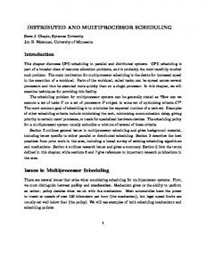
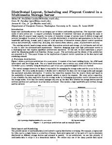
Carrier Aggregation Types There are two type of carrier aggregation techniques have been proposed for the LTE-Advanced mobile systems. x Continuous CA when multiple available component carriers are adjacent to each other “Fig. 1” x Non-continuous CA when multiple available component carriers are separated along the frequency band “Fig. 2” Figure 3. Data aggregation schemes at MAC layer
Figure 1. Continuous carrier aggregation
Figure 4. Data aggregation schemes at PHY layer Figure 2. Non-continuous carrier aggregation
III.
Carrier aggregation is a technology that aggregates multiple component carriers into an overall wider bandwidth. Each user can access only one component carrier till the end of its traffic in case of independent carrier. So the scheduler on each component carrier allocates the resource blocks (RBs) to the users who access it. LTE-Advanced UE can
DATA AGGREGATION SCHEMES
The transmission blocks (TBs) from different component carriers can be aggregated at either the medium access control (MAC) or physical layer (PHY).
391
packet of a user can use all the RBs on different component carriers, which leads to higher frequency selective gain. But the gain is un-conspicuous when the traffic load is high, such as Full Buffer traffic model whose queue waiting for transmission is always infinite.
share the overall wider bandwidth when the component carriers in different frequency bands are aggregated into a wider bandwidth. Each user can use RBs of all the component carriers simultaneously. There are two scheduler structures for aggregation in existence i.e. disjoint queue scheduler (DQS) and joint queue scheduler (JQS) [6]. A. Disjoint Queue Scheduler In case of disjoint queue scheduler structure the users’ traffic queue waiting for transmission is disjoint on different component carriers “Fig. 5”. Each user has one traffic queue on each component carrier. Two schedulers are adopted to map the users’ traffic to the RBs. The outer scheduler which is also known as first scheduler allocates the traffic packet of users to its corresponding queue to wait for transmission on each component carrier. The inner scheduler act as resource scheduler present on each component carrier. It maps the packets in the queue of different users to the RBs using the classic scheduling algorithm of multi-carrier systems. Outer scheduler follows load balancing strategy that means scheduler allocated the users’ packets to each component carrier according to the load of the component carrier. The load-based packet allocation strategy can balance the load of every component carrier, which leads to better user fairness. Inner scheduler follows multi-carrier proportion fair algorithm. Under this structure, a packet of a user can be allocated to only one component carrier, and only the RBs belonging to this component carrier can be assigned to the packet. So the efficiency is low, especially when the packets are large and sparse. On the other hand, the complexity of this scheduler is high.
Figure 6. Joint queue scheduler
IV.
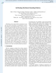
JQS WITH PRIORITY ANALYSER
Disjoint queue scheduler has deficiencies in term of processing overheads, complexity due to two level of scheduling, and low efficiency. Joint queue scheduler also has one known issue i.e. queue waiting infinite on high traffic load. To overcome these known issues we propose a scheduler i.e. joint queue scheduler with priority analyser. This scheduler is optimised JQS which has a priority analyser “Fig. 7”. It will read priority information from the buffered items and pass it to scheduler. Each user has only one queue for all the component carriers and the component carriers share the joint queue of each user. The priority analyser will analyse the priority of user and give preference to that user for scheduling. The role of priority analyser includes fetching the priority information from buffered traffic from each user; define priority among more than one user, and to maintain fairness. User may have more than one traffic items at a time. Each item must have priority information. Priority analyser fetches the priority information. There can be more than one user at a time, which has to traffic their data. Priority analyser defines the priority among the users on basis of their tariff priority, bandwidth requirement etc. There are benefits of including priority analyse in joint queue scheduler. These benefits include overall performance improvement, reduced average error, reduced latency and fairness.
Figure 5. Disjoint queue scheduler
B.
Joint Queue Scheduler In case of joint queue scheduler structure the users’ traffic queue waiting for transmission joint on different component carriers “Fig. 6”. Each user has only one queue for all the component carriers and the component carriers share the joint queue of each user. The shared scheduler maps the users’ traffic information to the RBs on all component carriers. This structure is also known as onelayer scheduler. This scheduler follows multi-carrier proportion fair algorithm i.e. classic for multi-carrier system. The efficiency of joint queue scheduler is higher than that of disjoint queue scheduler. In case of joint queue scheduler a
Priority of buffers mapping to resource block of specific component carrier priorities based upon following. x Threshold of buffer status x Application and its life x Expected time to complete Threshold of buffer status will help to take know the detail of buffer status and time to fill the buffer. e.g. Buffer status is more than 70% and expected buffer fill time is t1. The application kind and duration of application life for which buffer–RB mapping is happening, is also an
392
important parameter for priority analysis. e.g. browser application is running and its temporary suspension (or delay) would not impact on overall user experience. Expected time to complete the application is also a parameter to decide the priority. e.g. browser application is running for long and new application is an SMS/MMS, which will take relatively very small time to complete.
scheduling in LTE-Advanced for providing support for Inter-Cell Interference Coordination for the PDCCH in heterogeneous network deployments. ACKNOWLEDGMENT
We thank research supervisor and seniors of the organization for their support & encouragement.
We have seen the benefits of both carrier aggregation and proposed scheduler structure. It helps to achieve increase in user data rate, sector throughput, benefits in load balancing, improvement in packet latency and burst rate. V.
REFERENCES [1]
CONCLUSION
Carrier aggregation is significant technology for LTEAdvanced systems. There are three main motivations for introducing carrier aggregation for LTE-Advanced in Release 10: support of high data rates, efficient utilization of fragmented spectrum, and support of heterogeneous network deployments by means of cross-carrier scheduling. This research paper investigated about carrier aggregation, scheduler structures and finally concluded with a newly proposed idea of an improved scheduler structure for carrier aggregation. Further research extension may be focused onto study of the performance of carrier aggregation with different bandwidth and MIMO technology. The research may also be extended in a new dimension of cross-carrier
[2] [3] [4] [5] [6]
[7]
3GPP TR 36.913, ‘Requirements for further advancements for Evolved Universal Terrestrial Radio Access (E-UTRA) (LTEAdvanced)’ 3GPP “Summary of LTE Advanced Requirements presented at the workshop”, REV-080058, 2008. 3GPP “LTE-Advanced – LTE evolution towards IMT-Advanced Technology components”, REV-080030, 2008. 3GPP “Technologies for LTE-Advanced from RAN1 Perspectives”, R1- 081828, May. 2008. Eiko Seidel, "LTE-A HetNets using Carrier Aggregation", Nomor Research GmbH , June 2013 Li Chen, Wenwen Chen, Xin Zhang and Dacheng Yang, "Analysis and Simulation for Spectrum Aggregation in LTE-Advanced System", Vehicular Technology Conference Fall (VTC 2009-Fall), 2009 IEEE 70th, Sept. 2009 3GPP TS 36.300, “E-UTRA and E-UTRAN Overall Description Stage 2 (Release10),” Sep. 2011, v10.5.0.
Figure 7. JQS with Priority Analyser
393