Index Termsâ MIMO cognitive networks, beamforming, chan- nel uncertainty ..... Matrix Qk can be obtained by solving the following sub-problem. (P5) max. Qkâ½0 uk (Qk ... Problem (P4) can clearly be solved centrally at a CR fusion center, but ...
DISTRIBUTED ROBUST BEAMFORMING FOR MIMO COGNITIVE NETWORKS Yu Zhang, Emiliano Dall’Anese, and Georgios B. Giannakis Dept. of Electrical and Computer Engineering, University of Minnesota, Minneapolis, USA ABSTRACT Beamforming for multi-input multi-output (MIMO) cognitive networks is considered in the presence of channel uncertainty induced by errors in estimating cognitive-to-primary channels. A robust beamforming problem is formulated to optimize an appropriate cognitive radio network-wide performance metric, while enforcing protection of the primary system. In spite of the non-convexity of the resultant optimization problem, a block coordinate ascent algorithm is developed with provable convergence to a stationary point. Enticingly, the novel scheme also lends itself naturally to a distributed implementation. Numerical results are reported to corroborate the analytical findings. Index Terms— MIMO cognitive networks, beamforming, channel uncertainty, robust optimization, distributed computation.
ensuring protection of the PU system. To cope with the inherent non-convexity of the novel optimization problem, a block coordinate ascent approach is developed along with a local linear approximation technique to derive an iterative algorithm with provable convergence to a stationary point of the original non-convex problem. The resulting scheme is suitable for distributed operation, where each CR locally solves a convex sub-problem provided that relevant optimization parameters are obtained by measuring the interfering signals [8, 11]. Notation: Boldface lower (upper) case letters represent vectors (matrices). Hn×n , Cn×n and R stand for spaces of n×n Hermitian, n× n complex matrices, and real numbers, respectively, whereas Tr{·} denotes the trace operator; (·)H conjugate transpose, and vec(A) the vector obtained by stacking the columns of a matrix A; IN is the N ×N identity matrix. Finally, E{·} denotes the expectation operator.
1. INTRODUCTION The key enabler for seamless frequency re-use is the ability of cognitive radios (CRs) to judiciously control the interference inflicted to the incumbent primary user (PU) system [1]. However, as full cooperation between PU and CR nodes is generally infeasible in the advocated hierarchical access model, CR-to-PU channels are difficult to acquire in practice. Consequently, interference is challenging to control. It is thus of paramount importance to take into account the inherent randomness of the CR-to-PU channels, and enforce PU protection throughout the CR network operation [2, 3, 4]. Recently, MIMO CR networks have attracted considerable attention thanks to their ability to mitigate self- and PU-inflicted interference via beamforming, while leveraging spatial multiplexing and diversity to markedly increase transmission rates and reliability. On the other hand, wireless transceiver optimization has been extensively studied in recent years when either perfect or imperfect channel state information (CSI) is available [5, 6]. In the CR context, network utility maximization was investigated under perfect CSI knowledge in e.g., [7, 8] and references therein. CR-toPU channel uncertainties were considered with single-antenna PUs, identical channel estimation errors for different CR-to-PU links, and only for centralized operation [3, 4, 9]. The present paper considers a MIMO ad-hoc CR network deployed to share the spectrum bands licensed to PUs, who are also equipped with multiple antennas. The inherently stochastic nature of the propagation environment, and the inevitable inaccuracies of the CR-to-PU channel estimates are captured by a Frobenius normbounded uncertainty model [10, Ch. 4], which leads to a robust interference constraint ensuring PU protection [2, 4]. Upon recasting the robust constraint in a convenient form, a resource allocation problem is formulated to obtain CR transmit- and receive-beamforming matrices minimizing the overall data symbol estimation error, while This work was supported by QNRF grant NPRP 09-341-2-128. E-mails: {zhan1220, emiliano, georgios}@umn.edu
978-1-4673-0046-9/12/$26.00 ©2012 IEEE
2953
2. PROBLEM FORMULATION Consider a wireless MIMO CR network comprising K transmitterreceiver pairs {Ukt , Ukr }, sharing spectrum resources with an incumbent PU system in an underlay setting [1]. Let Mk and Nk , k ∈ K := {1, 2, . . . , K}, denote the number of antennas of the k-th transmitter and receiver, respectively; and sk the Mk × 1 information-bearing symbol vector transmitted by Ukt per time slot with covariance matrix E{sk sH k } = IMk . In order to alleviate CR mutual interference, Ukt pre-multiplies sk by a transmitbeamforming matrix Fk ∈ CMk ×Mk ; that is, Ukt actually transmits the Mk × 1 symbol vector xk := Fk sk . With Hk,j ∈ CNk ×Mj denoting the channel of CR link Ujt → r Uk , the Nk × 1 symbol vector received at Ukr is � Hk,j xj + nk (1) yk = Hk,k xk + j∈K\{k}
where nk ∈ CNk denotes the zero-mean complex Gaussian noise, 2 independent of sk , with covariance matrix E{nk nH k } = σk INk . Low-complexity receiver processing motivates the use of a computationally-affordable linear filter Wk ∈ CMk ×Nk at Ukr to recover sk as ˆsk := Wk yk . Using Wk at Ukr , the mean-square error (MSE) matrix Ek := E{(ˆsk − sk ) (ˆsk − sk )H }, which quantifies the reconstruction error, is given by [cf. (1)] H H Ek = Wk Ak WkH − Wk Hk,k Fk − FH k Hk,k Wk + IMk
(2)
�K H H 2 where Ak := j=1 Hk,j Fj Fj Hk,j + σk INk . Entry (i, i) of Ek represents the MSE of the i-th data stream from Ukt to Ukr , and Tr{Ek } corresponds to the MSE of ˆsk . Among candidate network performance metrics, the adopted one in this paper is the sum of MSEs from different data streams. This metric relates to system performance in terms of bit error rate (BER) as explained in [6], and
ICASSP 2012
Using the covariance of transmitted symbols Qk := E{xk xH k } = Fk FH k as optimization variable, (P 2) can be expressed as
facilitates derivation of the optimal filters. To account for different quality-of-service demands, its weighted counterpart can be adopted as in [12]. To complete the formulation, let Gk ∈ CL×Mk denote the channel between CR Ukt and a PU receiver, possibly equipped with multiple (L) antennas.1 Then, the transmit- and receive-beamforming matrices minimizing the overall MSE can be obtained as (P 1)
K �
min
{Fk ,Wk }K k=1
s.t.
Tr{Ek }
(P 3)
(3b)
H max ,k∈K Tr{Gk Fk FH k Gk } ≤ ι k
(3c)
k=1
+
K �
� � max λk Tr{Fk FH k } − pk
�
H max νk Tr{Gk Fk FH k Gk } − ι k
� (4)
k=1
where P := {{Fk }, {Wk }} and D := {{λk }, {νk }} collects the primal and dual variables, respectively. Then, by setting the complex gradient ∂L/∂Wk∗ equal to zero, Wkopt is found as =
H −1 FH k Hk,k Ak ,
k ∈ K.
Substituting back into (3a), and neglecting irrelevant terms, it follows that (P 1) can be equivalently re-written as (P 2)
max
{Fk }
(7b)
max , k∈K Tr{Gk Qk GH k } ≤ ιk
(7c)
� 2 with Rk,k := i�=k Hk,i Qi HH k,i + σk INk . Channels {Gk } must be perfectly known in order to solve (P 3). A robust version of (P 3), which accounts for imperfect channel knowledge, is dealt with in the next section.
3. ROBUST CR BEAMFORMERS In typical CR scenarios, CR and PU nodes do not generally cooperate. Thus, CR-to-PU channels are challenging to estimate accurately. To capture estimation inaccuracies, consider expressing Gk as ˆ k + ΔGk , k ∈ K Gk = G
� � H −1 Tr Hk,k Fk FH k Hk,k Ak
� � 2 Gk := ΔGk |Tr{ΔGk ΔGH k } ≤ �k , k ∈ K
(9)
(6)
k=1
s.t. (3b), (3c). 1 A single PU receiver is considered throughout the paper. However, extension to multiple receiving PU devices is straightforward.
2954
(10)
where �k > 0 controls the degree of uncertainty associated with Gk . For example, (9) properly models the case where a time division duplex (TDD) strategy is adopted by the PU system, and CRs have prior knowledge of the PUs’ pilot symbols [3]. In lieu of pilot ˆ k } can be formed using the path loss coefficients, and symbols, {G �k can be deduced from the fading statistics. Based on (10), a robust interference constraint can be written as ˆ k + ΔGk )H } ≤ ιmax ˆ k + ΔGk )Qk (G , Tr{(G k ∀ ΔGk ∈ Gk , k ∈ K
(11)
and thus, a robust counterpart of (P 3) is
(5)
{Wkopt }
K �
, k∈K Tr{Qk } ≤ pmax k
ˆ k is the estimated channel available to Ukt , and {ΔGk } the where G uncertainty error taking values from the bounded set
k=1
Wkopt
(7a)
� � �−1 H (8) H Q H + R uk ({Qk }) := Tr Hk,k Qk HH k,k k k,k k,k k,k
For the sum-MSE cost in (3a), it will turn out that Wk can be obtained in closed form. To see this, note first that for fixed {Fk }, (P 1) is convex in Wk , and the optimum {Wk }s can be obtained from the first-order optimality conditions. Express the Lagrangian function associated with (P 1) as K �
uk ({Qk })
k=1
where the per-CR link utility uk ({Qk }) is given by
k=1 max Tr{Fk FH ,k∈K k } ≤ pk
Tr{Ek } +
K �
(3a)
2.1. Equivalent Optimization Problem
K �
{Qk �0}
s.t.
is the maximum transmit-power of Ukt , and ιmax the where pmax k k maximum interference CR Ukt can afford to inflict to the PU. As in e.g., [1, 11], partitioning of the interference budget ιmax := � max in per-CR transmitter portions {ιmax } is assumed carried k k ιk out beforehand, possibly according to quality-of-service guidelines. However, due to lack of explicit cooperation between PU and CR nodes, CR-to-PU channels {Gk } are in general difficult to estimate accurately. As PU protection must be enforced strictly, it is important to take into account the inherent channel uncertainty in the CR-to-PU links and guarantee that the interference power experienced by the PU receiver stays below a prescribed level for any possible (random) channel realization [2, 4]. Before developing a resource allocation approach robust to inaccuracies in channel estimates, problem (P 1) is conveniently re-formulated first in order to reduce the number of variables involved.
L (P, D) =
max
(P 4)
max
{Qk �0}
s.t.
K �
uk ({Qk })
(12)
k=1
(7b), (11).
opt Clearly, once {Qopt k } solving (P 4) is found, {Wk } can be readily computed via (5). � However, k uk ({Qk }) is non-convex in {Qk }, and hence (P 4) is hard to solve in general. Additionally, constraints (11) are not in a tractable optimization form, and thus further elaboration is needed. These issues are addressed in the next section.
Algorithm 1 Distributed robust sum-MSE minimization
3.1. Distributed algorithm via local approximation
1: 2: 3: 4: 5: 6: 7: 8: 9:
To cope with the non-convexity of the utility function in (P 4), a block-coordinate ascent approach is adopted. Define first the sum � of all but the k-th utility as fk (Qk , Q−k ) := j�=k uj , which is convex in Qk [cf. Lemma 2]. By keeping only the linear term of ¯ k }, the the Taylor’s expansion of fk (·) around a feasible point {Q objective function in (12) can be approximated as (see also [8]) K �
uk ({Qk }) = uk ({Qk }) + fk (Qk , Q−k )
Initialize Qk = 0, ∀ k ∈ K. repeat for k = 1, 2, . . . , K do Measure Rk,k . Exchange {Bj , Vj , Hj,k } with interfering CR links. Update Qk by solving (P 6). end for until convergence Update Wk via (5).
k=1
� � ¯ k , Q−k ) + Tr DH ¯ ≈ uk ({Qk }) + fk (Q (13) k (Qk − Qk )
¯ k , Q−k ) := where Dk := ∇Qk fk (Q
∂fk
∂Q∗ k
¯k Qk =Q
. Matrix Qk can
be obtained by solving the following sub-problem � � (P 5) max uk (Qk , Q−k ) + Tr DH k Qk Qk �0
s.t.
where
Bj :=
Tr{Qk } ≤ pmax k
(14b)
max , ∀ ΔGk ∈ Gk Tr{Gk Qk GH k } ≤ ιk
(14c)
� H −1
−1 Dk := − Hj,k Bj Vj Bj Hj,k
j�=k K �
(14a)
Proposition 1 There exists sk ≥ 0 for which (14c) is equivalent to � ˆH −vec(QH sk IL×Mk − (IL ⊗ Qk ) k Gk )
0. 2 ˆ k Qk G ˆH H ˆH −vec(QH ιmax − Tr{G k Gk ) k k } − �k s k (19) Using Schur complement, (P 5) can be equivalently reformulated as � � (20a) (P 6) min Tr {T} − Tr DH k Qk Qk �0 T,sk ≥0
(15) ¯k Qk =Q
� 2 H Hj,i Qi HH j,i + σj INj , and Vj := Hj,j Qj Hj,j . (16)
s.t.
Tr{Qk } ≤ pmax k
Hk,k Qk HH k,k 1/2 Rk,k
+ Rk,k
1/2 Rk,k
T
sk IL×Mk − (IL ⊗ Qk ) ˆH H −vec(QH k Gk )
(20b)
�
0
ˆH −vec(QH k Gk ) max 2 ˆ ˆ ιk − Tr{Gk Qk GH k } − � k sk
0. (20d)
i=1
Problem (P 4) can clearly be solved centrally at a CR fusion center, but the coordinate ascent approach suggests also a distributed optimization procedure; in fact, each CR Ukt can update locally Qk ¯ k obtained at the previous iterbased on: i) its covariance matrix Q ation of the algorithm, that is to be used in (13); ii) a measurement of the interference perceived Rk,k (see also [8]); and iii) matrices {Bj }, {Vj }, and {Hj,k } obtained from the neighboring CR links via local message passing. 3.2. Equivalent robust interference constraint Constraint (14c) renders (P 5) a semi-infinite program. An equivalent constraint in linear matrix inequality (LMI) form will be derived in this section. This will turn (P 5) into an equivalent semidefinite program (SDP), which can be efficiently solved in polynomial time by standard interior point methods [10]. To this end, the following lemma is useful. Lemma 1 (S-Procedure [10, p. 655]) Let A, D ∈ Hn×n , b ∈ Cn , ¯ satisfying x ¯ H D¯ and c, e ∈ R, and assume that there exists an x x< e. Then, the inequality H
H
H
x Ax + 2�(b x) + c ≥ 0, ∀ x Dx ≤ e holds if and only if there exists a scalar s ≥ 0 such that � sD + A b
0. bH c − es
(17)
(18)
Using Lemma 1, (14c) can be equivalently reformulated as follows.2 2 Proofs
(20c)
can be found in [13].
The overall distributed scheme implemented via nonlinear Gauss-Seidel iterations is tabulated as Algorithm 1. Notice that covariances can be alternatively updated using the Jacobi iteration [14, Ch. 2]. 4. CONVERGENCE Since the original optimization problem (P 4) is non-convex, convergence of the coordinate ascent solver has to be established. To this end, recall that (P 5) and (P 6) are equivalent; thus, convergence can be asserted by supposing that (P 5) is solved per Gauss-Seidel iteration instead of (P 6). The following lemma is first needed. Lemma 2 For each k ∈ K, the feasible set of problem (P 5), namely Qk := {Qk |Qk ∈ (14b), (14c)} is convex. And the realvalued function fk (Qk , Q−k ) is convex in Qk over the feasible set Qk , whenever {Qj , j = k} are fixed. Based on Lemma 2, convergence is established next. Proposition 2 The sequence of objective function values obtained by the coordinate ascent Algorithm 1 converges. Interestingly, by inspecting the structure of the channel matrices {Hk,k , k ∈ K} of links {Ukt → Ukr }, it is possible to show that the coordinate ascent algorithm not only converges, but also that the limit point satisfies the first-order optimality conditions as summarized in the following theorem. Theorem 1 If matrices Hk,k , k ∈ K, have full column rank, then every limit point of Algorithm 1 is a stationary point of (P 4).
2955
1
8
0.9
7.5
0.8
7
0.7
Sum MSE
cdf
0.6 0.5 0.4 0.3
6.5 6 5.5 5
0.2
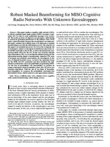
(P3), non−robust design (P6), robust design Interference threshold
0.1 0
SNR = 10dB SNR = 20dB SNR = 30dB
0
1
2
3 4 interference power [W]
5
4.5
6
4 0
7 −7
x 10
Fig. 1: Interference cumulative distribution function.
1
2
3
4
5 6 7 8 9 Iteration number n
10
11
12
13
14
Fig. 2: Algorithm convergence.
The proof of Theorem 1 is in the spirit of the convergence claim of the block coordinate descent method in [14, Ch. 2], [5]. What is basically needed to show is that the limit point of the algorithm satisfies the first-order optimality conditions over the Cartesian product of closed convex sets; see [13] for detailed proof. 5. NUMERICAL RESULTS In this section, numerical results are presented to verify the performance merits of the novel design. Four CR pairs and one PU receiver are considered, all are equipped with 2 antennas. The path loss obeys the model d−η , with d the distance between nodes, and η = 3.5. A flat Rayleigh fading model is employed. For simplicity, the distances of links Ukt → Ukr are all set to dk,k = 30 m; for the interfering links {Ukt → Ujr , j = k} distances are uniformly distributed in the interval 30 − 100 m. Finally, CR-to-PU distances are uniformly distributed in 70 − 100 m. The maximum transmit-power and the noise power are identical for all CRs. To validate the effect of the robust interference constraint, the cumulative distribution functions (CDF) of the interference power perceived by the PU are depicted in Fig. 1. Transmit-powers and noise powers are set so that the signal-to-noise ratio defined as 2 SNR := pmax (d−η k k,k )/σk equals 10 dB. The total interference threshold ιmax = 3 · 10−7 W is equally split among the CR transmitters. ˆ k 2F . CDF curves The channel uncertainty is set to �2k = 0.08 · G are obtained over 4, 000 independent channel realizations using Monte Carlo simulations. As expected, the proposed robust scheme enforces the interference constraint strictly. In fact, the interference never exceeds the tolerable limit (shown as the vertical red dashed line). On the contrary, its non-robust counterpart frequently violates the interference limit (more than half of the times). Fig. 2 illustrates the convergence of the proposed iterative algorithm for a given channel realization with different SNRs. It is clearly seen that the total MSE decreases monotonically across fastconverging iterations. 6. REFERENCES [1] Q. Zhao and B. M. Sadler, “A survey of dynamic spectrum access,” IEEE Sig. Proc. Mag., vol. 24, no. 3, pp. 79–89, May 2007. [2] E. Dall’Anese, S.-J. Kim, G. B. Giannakis, and S. Pupolin, “Power control for cognitive radio networks under channel un-
2956
certainty,” IEEE Trans. Wireless Commun., vol. 10, no. 10, pp. 3541–3551, Oct. 2011. [3] T. Al-Khasib, M. Shenouda, and L. Lampee, “Dynamic spectrum management for multiple-antenna cognitive radio systems: Designs with imperfect CSI,” IEEE Trans. Wireless Commun., vol. 10, no. 9, pp. 2850–2859, Sep. 2011. [4] G. Zheng, K.-K. Wong, and B. Ottersten, “Robust cognitive beamforming with bounded channel uncertainties,” IEEE Trans. Sig. Proc., vol. 57, no. 12, pp. 4871–4881, Dec. 2009. [5] M. Razaviyayn, M. Sanjabi, and Z.-Q. Luo, “Linear transceiver design for interference alignment: Complexity and computation,” 2010, http://arxiv.org/abs/1009.3481. [6] M. Ding and S. D. Blostein, “MIMO minimum total MSE transceiver design with imperfect CSI at both ends,” IEEE Trans. Sig. Proc., vol. 57, no. 3, pp. 1141–1150, Mar. 2009. [7] R. Zhang and Y.-C. Liang, “Exploiting multi-antennas for opportunistic spectrum sharing in cognitive radio networks,” IEEE J. Sel. Topics Sig. Proc., vol. 2, no. 1, pp. 88–102, Feb. 2008. [8] S.-J. Kim and G. B. Giannakis, “Optimal resource allocation for MIMO ad hoc cognitive radio networks,” IEEE Trans. Info. Theory, vol. 57, no. 5, pp. 3117–3131, May 2011. [9] E. A. Gharavol, Y.-C. Liang, and K. Mouthaan, “Robust linear transceiver design in MIMO ad hoc cognitive radio networks with imperfect channel state information,” IEEE Trans. Wireless Commun., vol. 10, no. 5, pp. 1448–1457, May 2011. [10] S. Boyd and L. Vandenberghe, Convex Optimization, Cambridge University Press, 2004. [11] G. Scutari and D. P. Palomar, “MIMO cognitive radio: A game-theoretical approach,” IEEE Trans. Sig. Proc., vol. 58, no. 2, pp. 761–780, Feb. 2010. [12] S. S. Christensen, R. Agarwal, E. de Carvalho, and J. M. Cioffi, “Weighted sum-rate maximization using weighted MMSE for MIMO-BC beamforming design,” IEEE Trans. Wireless Commun., vol. 7, no. 12, pp. 4792–4799, Dec. 2008. [13] Y. Zhang, E. Dall’Anese, and G. B. Giannakis, “Distributed optimal beamformers for cognitive radios robust to channel uncertainties,” IEEE Trans. Sig. Proc., 2012 (submitted). [14] D. P. Bertsekas, Nonlinear Programming, Athena Scientific, Belmont, MA, 2nd edition, 1999.