Distributed Simulation using the Virtual Test Bed and its Real-Time Extension J. L. Bastos, J. Wu, N. Schulz Department of Electrical and Computer Engineering Mississippi State University
[email protected],
[email protected],
[email protected]
R. Liu, A. Monti Department of Electrical Engineering University of South Carolina
[email protected],
[email protected]
Keywords: Distributed simulation, distributed real-time simulation, VTB, VTB-RT. Abstract Distributed simulation is desirable at many levels of system design. Modeling and simulation of large complex systems, remote monitoring and control, and nondestructive remote testing of devices are three examples of the many applications in which both distributed and realtime distributed simulation are advantageous. Distributed simulation reduces simulation complexity by allowing the partitioning of a large complex system into two or more smaller subsystems. In addition, distributed simulation permits computational resource sharing and enables teamwork. The Virtual Test Bed (VTB) and its real-time extension, VTB-RT, have been adapted to deal with distributed simulation in both non-real-time and real-time. Efforts at Mississippi State University and the University of South Carolina have made possible the addition of models for distributed simulation to the VTB model library to handle both natural and signal coupling at the decoupling point. The focus of these efforts has been on the algorithms used to enforce simulation stability and energy conservation in a distributed environment. Implementation issues related to the different communication architectures used in distributed simulation environments are only briefly discussed in this paper. The models for distributed simulation described in this paper are implemented using a simple remote procedure call communication scheme, which is sufficient to demonstrate the proposed algorithms. Several examples presented in this paper demonstrate the applicability and accuracy of the developed VTB models.
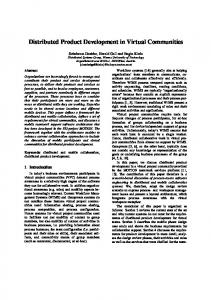
Figure 1. Conceptual Topology of Distributed Simulation The first step in the implementation of a distributed simulation application is to decouple the whole system into multiple subsystems. The subsystems are then solved separately using distributed computational resources. Finally, the results of the subsystems are combined to obtain the overall system solution. In this process, two critical issues are the point at which the system is partitioned or decoupled, and the method used to decouple the system. These issues significantly affect the results of the distributed simulation, whose stability and convergence depend on the decoupling method and the subsequent coupling scheme used to enforce determined system properties at the decoupling point. Various solutions to overcome these problems have been proposed by researchers at different universities. In particular, Mississippi State University (MSU) and the University of South Carolina (USC) have contributed to the implementation of simulation models for distributed simulation in the context of the Virtual Test Bed (VTB), a simulation environment sponsored by the Office of Naval Research (ONR) that provides a high level of model library customizability. Among the advantages of VTB are: i) support of multidisciplinary models, ii) support of signal as well as natural coupling among models, and iii) advanced visualization interface. VTB is especially useful in the simulation of power system and power electronics applications because of its object-oriented approach based on the resistive companion method, which ensures energy conservation at the models’ interface ports. VTB’s real-time
1.
INTRODUCTION In distributed simulation, the system under study is divided into stand-alone subsystems that run on separate computers or processors. The dynamics of these several parts of the whole system are then computed separately and concurrently, providing a way to share the computational load by multiple computers and, thus, effectively reducing the simulation time. A conceptual topology of distributed simulation is shown in Figure 1.
SCSC 2007
757
ISBN # 1-56555-316-0
extension, VTB-RT, is based on the same solver principles and offers similar advantages for real-time simulation of power systems. In power system applications, the solution of the subsystems’ equations in distributed simulation cannot be found separately because at every simulation step subsystems must interchange variables (i.e. voltages and currents) to achieve power transfer. Both MSU [3][13] and USC [9][11] have proposed coupling methods to enforce physical conservation laws at the decoupling point. The theory behind these coupling methods has been mathematically described and compared in [11]; however, MSU’s and USC’s proposed generalized coupling methods had not been analyzed in the same context before. This paper will provide a review of the different models that exist in the VTB library for distributed simulation. The different coupling schemes utilized for the implementation of these models are reviewed in detail. However, the different communication technologies and software strategies for parallel execution are not analyzed in this paper. A simple remote procedure call (RPC) over transmission control protocol (TCP) communication scheme is implemented in all models described in this paper. Other communication architectures could be considered in future developments of these models. MSU’s contribution is the implementation of VTB models that allow for natural and signal distributed simulation for power system analysis of single- and threephase cases. USC’s contribution is the implementation of models for distributed simulation in both non-real- and realtime. Application examples that successfully use each of these distributed simulation models for natural and signal coupling are presented in this paper. In all of these application cases, the comparison of distributed and nondistributed simulation results shows that the VTB and VTBRT models for distributed simulation provide a reliable platform for advanced distributed simulations. 2.
distributed simulation models described in this paper are handled from the VTB graphical user interface and can run on computers running the Windows 2K operating system. 2. VTB simulation software provides a flexible and open architecture, where users can work at three different levels: application level, modeler level, and solver designer level. Users can develop and customize VTB models by using C++ [14]. 3. VTB’s solver provides support for both natural and signal coupling models. A key characteristic of the VTB solver is the use of the resistive companion method (RCM), which is a modeling technique that has been widely used in time-domain simulation software such as PSpice, PSIM and PSCAD [14]. The RCM allows modeling of every single object in the system as a separate entity and easily interconnection of these objects into a network. By using the RCM, physical conservation laws are enforced on natural coupling ports connecting two or more components. The agreement with this basic phenomenon makes VTB suitable for power system simulation. Decoupling the system at a signal connection point poses few design complications with respect to decoupling the system at a natural coupling level. To ensure the conservation of energy at the decoupled boundary, VTB requires an interface model that can support natural coupling. Interface models for both signal and natural coupling are implemented as Server/Client virtual objects that keep the correct voltage and current values at both ends of the decoupled system in the natural coupling case. VTB-RT is based on the Linux version of the Virtual Test Bed. Since its introduction in 2002, VTB-RT has been developed as a low-cost and customizable platform for realtime simulations and hardware-in-the-loop testing applications. VTB-RT has been applied in distributed simulations at both the signal and natural coupling levels, as reported in [2] and [16]. For real-time distributed simulation, models for VTB-RT have been implemented as well as an interrupt module with global positioning system synchronization to enable exchange of signals among subsystems in real-time.
VTB AND VTB-RT SIMULATION ENVIRONMENT
The Virtual Test Bed (VTB) is a software tool developed at the University of South Carolina (USC) under the Office of Naval Research (ONR) sponsorship. VTB is freely available at USC’s website (http://vtb.engr.sc.edu). VTB is a multidisciplinary simulation environment, which covers the areas of electrical, thermal, chemical and mechanical engineering research. VTB offers a number of advantages as a simulation environment. 1. VTB’s graphical user interface is interactive and provides advanced visualization capabilities. The
ISBN # 1-56555-316-0
3.
DISTRIBUTED SIMULATION CONSIDERATIONS
3.1. Decoupling Method The decoupling method is an important issue for distributed simulation, because, as mentioned earlier, the decoupling point and the way of decoupling a system significantly affect the simulation results. An electric system can be partitioned using different techniques. Some ideas
758
SCSC 2007
simple first-order system. However, the performance of the coupling method depends on the system to be decoupled, which means that different types of tests cases should be used when comparing these decoupling methods.
about system partitioning come from circuit analysis and simulation where efficient techniques are needed to solve the electric circuits whose sizes are increasingly large. A relaxation algorithm [7] and transmission-line modeling [10] can be applied in solving and analyzing the circuits. The Relaxation algorithm uses an iterative process to solve the equations by applying Kirchoff’s law. GaussSeidel and Gauss-Jacobi are two typical relaxation algorithms. Their basic process is as follows. First, the system is decomposed into several subsystems. Second, the relaxation algorithm is applied to solve each of the subsystems with a guessed initial condition. In each iteration, subsystems are solved individually by using the approximate boundary values of the neighboring subsystem. Next, the boundary values are updated at every iteration. The iterative process goes on until the solutions converge or a pre-specified number of iterations is reached. In order to achieve a reasonable convergence rate, a trade off has to be made when partitioning the system. The system should be partitioned at places where the coupling is weak and the subsystems should contain minimal nodes at the same time. Note that this is a trade off for the designer because if too many tightly coupled elements are in a same subsystem, the advantage of using the relaxation algorithm is weakened. Reference [8] suggests partitioning the power system based on coherent groups. Another issue associated with relaxation algorithm based partitioning method is the pattern of the equivalent circuit that represents the neighboring subsystem. Reference [10] compared three types of coupling patterns and how they affect the convergence of the solution. The transmission line modeling (TLM) technique [10] is based on the concept of magnetically coupled circuits. TLM is also a discrete modeling method and provides a general approach for decoupling systems in distributed simulation. According to this method, the decoupling point should be chosen at passive elements in the system, where the voltage or current change slowly. In addition, the simulation time step should be relatively small. By doing this, the decoupled subsystems can be considered as connected by means of a constant voltage or current source, and the error due to time delays can be significantly decreased. This method is mostly applied in power electronics systems, since these systems usually contain various power stages and switching devices. Other benefits of this technique include: 1) increased efficiency and accuracy, since TLM can derive a discrete model directly from the physical system, bypassing the error of discretizing the continuous-time model; and 2) support for system decoupling into several parts. Decoupling methods based on other techniques, such as ideal transformer model (ITM) and time-variant first-order approximation (TFA), are also introduced in [11], where the mentioned methods are compared by applying them to a
SCSC 2007
3.2. Network requirement Special attention is needed for the underlying network of a distributed simulation, because it directly affects the performance of a distributed simulation. The network can introduce a time delay and data errors into the distributed simulation. Currently, time delay is the biggest issue for distributed simulation. Time delays significantly affect natural coupling and signal coupling distributed simulation in different ways. For natural coupling distributed simulation, equivalent circuits are built in the subsystems to represent the neighboring subsystem. This means, at each time step, the solution of each subsystem depends on the last solution of other subsystem. The boundary value of each subsystem is updated and transferred to each other. A too large communication latency can cause the boundary values not to update timely, and thus, the convergence rate of the solution is slowed down. A time delay can also significantly affect distributed simulation with signal coupling when the decoupling point is located in a feedback control loop. In this scenario, a time delay can decrease the phase margin of the closed-loop control system, causing it to lose stability. Some solutions around this problem involve redesigning the controller to compensate for the time delay. Generally speaking, a distributed simulation requires a network with low latency, low-latency variance, and reliable, secure delivery and multicasting [12]. A low latency in the distributed simulation requires a certain level of bandwidth of the communication network (e.g. Internet). Also, lack of bandwidth will lead to loss of data. In the case of the Internet, the network communication normally adopts a packet switching technique, which allows the data path in the network to be shared by many users. If there is too much data transferring on the Internet, shortage of the bandwidth will occur and packets will be lost. Therefore, it is necessary to ensure a sufficient bandwidth for distributed simulation and Quality of Service (QoS) is necessary for distributed simulation, because it provides a way to manage the bandwidth and priority of the Internet. This service could be provided by IPv6 of the next generation of the Internet, which is one of the communication options that is being currently investigated for distributed simulation. 4.
DESIGN APPROACHES Based on the design considerations described in the previous section, MSU proposed a coupling scheme for the interface between the subsystems [13]. The systems were partitioned by VI overlap decoupling pattern, which is based on the relaxation algorithm.
759
ISBN # 1-56555-316-0
are connected represent interfaced subsystems in the distributed simulation.
V1
Sub system A
v2(t), i2(t) i1
V2
Transmission Line G_Stable
iLoad Controlle G_Stable d by v2&i2 v1(t), i1(t)
V1
i2
Transmission Line iSource Controlled by v1&i1
V2 V2
Sub system B
Figure 4. GCS Interface Object in VTB
The most important parameters of both Server and Client objects are: Impedance of the stabilizing resistance (Rst): sets the initial value of the interface resistances (r1 and r2 in theoretical analysis). Default value: 1Ω. Tolerance: sets the maximum voltage error between Server and Client. Default value: 7x10⁻⁹ V. Auto-adjustment of stabilizing resistance Rst: implements the cases studied in the previous section for the calculation of r1 and r2. This version allows 3 user options. o Auto-adjustment after j iterations: the simulation will calculate Rst using the specified number of iterations j at each time step. This is required to achieve the specified tolerance. This option is useful for simulating most circuits with the highest precision. Default value: 4 iterations. o Auto-adjustment only at the first time step: the simulation will adjust Rst at the first time step, and then will perform only one iteration at each time step. This case is useful for linear systems with constant simulation time step (e.g. real-time simulations). o Absent: No auto-adjustment of Rst is performed. This case is useful for simple linear systems. Type of intercommunication: sets the type of communications between a server and a client. Two options are provided: RPC (Remote Procedure Call) or pipes. RPC refers to the case in which workstations are connected on a network (RPC protocol can be either TCP/IP or UDP/IP). Pipes are used when a section of shared memory is used for communication between separate processes. The Server model always initiates the communication process. During each iteration, across (Vi) and through (Ii) variables are transmitted from Server to Client and vice versa. Then these variables are calculated on both sides and transmitted again. The Server and Client VTB model icons are shown in Figure 5. Different Server models can run in decentralized computers as long as their respective Client pairs are defined as a parameter in the Server models.
Figure 2. MSU’s proposed decoupling scheme The whole and decoupled systems are shown in Figure 2. This decoupling scheme was implemented on the Virtual Test Bed (VTB) where natural coupling, signal coupling and their combination distributed simulation were built and tested on several terrestrial power systems and one shipboard power system. USC proposed a generalized coupling scheme (GCS), as shown in Figure 3 interfacing subsystems A and B. At every time step, these subsystems exchange current and voltage values (I1, V1 « I2, V2) according to the rules established by the coupling scheme. The GCS uses ideal current and voltage dependent sources, whose values correspond to the current and voltage in the kth time step, and two resistors r1 and r2, which act as stabilizing elements in the coupling scheme. Through theoretical analysis of the GCS, the role of resistors r1 and r2 is explained in terms of simulation stability.
Figure 3. USC Generalized coupling scheme (GCS) with subsystems A and B
The USC GCS simulation interface object is implemented following the modeling standards of the Virtual Test Bed (VTB). The main application of the interface object described herein is distributed simulation (e.g. using different computers connected on a network). The model is composed of two symmetric parts: Server and Client, as shown in Figure 4. Server’s and Client’s parts whose ports
ISBN # 1-56555-316-0
760
SCSC 2007
Figure 5. VTB Icons for Server and Client models
In VTB-RT, natural coupling is achieved through the interface described in [11], namely the TFA-based interface. To implement the Server/Client models of the TFA-based interface, the resistive companion conductance matrix and the history vector of the TFA-based interface, which are reproduced here for convenience from [11], are partitioned as follows: 1 R eq − 1 G = Req 0 0 0
1 Req 1 Req 0
0
0 0
0 1
−
0 0
1 1 − R Req eq G Server = 1 − 1 Req Req 0 0 − 1 GClient = 0 0 1 1 − 1 0
0 0 0 0 − 1 0 1 −1 0 0
− I eq I eq B= 0 0 V 1
− I eq BServer = I eq 0 BClient = 0 V1
Figure 6. Network communication using socket procedures with TCP protocol
5.
APPLICATION EXAMPLES The VTB model library has been enriched with Server/Client model for distribution simulation as described in previous sections. Contributions from USC and MSU have provided both VTB and VTB-RT with a variety of models that allow VTB instances to run on different computers and communicate through a network to converge to a unique, stable solution for the original system. Three examples that demonstrate the application of these models for distributed simulation in VTB and VTB-RT are presented next. These examples show medium-sized systems with a moderate degree of complexity. Implementations issues such as the network bandwidth, computer processing speed and scalability of the distributed simulation platform have not been analyzed in this paper, but will be considered in future work.
(1)
(2)
(3)
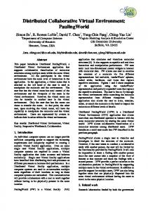
5.1. Testbench using MSU’s VTB models for Distributed Simulation In Figure 7, a three phase power system is divided into three subsystems, with one natural coupling port and one signal coupling port, thus this distributed simulation runs on three computers connected by the network. Figure 7 shows the schematic of the distributed simulation and Figure 8 shows the comparison between the distributed and non-distributed results where x axis indicates time (s) and y axis indicates current (A).
Network communication is achieved by using sockets. A socket is a data structure maintained by Linux to handle network connections. Two processes wishing to communicate over a network create a socket each. Two types of protocols are handled by sockets: TCP and UDP. In our case, TCP is chosen; therefore, the network communication is connection-based. This means that one process (Server) makes its socket known to the system using ``bind'', allowing other sockets to find it. The Server then ``listens'' on this socket to ``accept'' any incoming messages. The other process (Client) establishes a network connection to it, and then the two exchange messages. As many messages as needed may be sent along this channel, in either direction as shown in Figure 6.
SCSC 2007
761
ISBN # 1-56555-316-0
Figure 9. The whole system before separation
Figure 7. Schematic of Distributed Simulation with Both Natural Coupling and Signal Coupling server/Client models
Figure 10. Client-side subsystem after separation
Figure 8. Phase Current Comparison between Distributed and Non-Distributed Simulation
5.2. Testbench using USC’s VTB models for Distributed Simulation The whole system is a Notional Power Generation System for shipboard power system with four generators, AC zones and two DC zones. There are over 100 nature nodes in the whole system. After the split, there are more than 20 nature nodes in the Server-side subsystem and 90 nature nodes in the Client-side subsystem. The system is partitioned at a DC zone. The interface models (Server/Client models) exchange DC currents and voltages. The simulation results of the whole system and separated systems are the exactly the same. Figure 14 and Figure 15 show the 3-phase load voltages RLa, RLb and RLc in the hierarchical entity of zone 3. In Figure 15, zone 3 runs in the Server side of the distributed simulation. From these plots, it can be concluded that the Server/Client distributed simulation models implemented using the GCS proposed by USC work properly.
ISBN # 1-56555-316-0
Figure 11. Client side subsystem after separation
Figure 12. AC Bus 3-phase voltages before system partitioning
762
SCSC 2007
of this simple application is to show the performance of the dc-bus and power converter parts once they are separated into different subsystems, as shown in Figure 17. The Server and Client VTB objects shown in this figure allow network communication between the computers running the two separate subsystems.
Figure 13. AC Bus 3-phase voltages after system partitioning Figure 16. Application: DC motor drive VTB schematic
Figure 17. Distributed simulation of DC motor drive
The experimental results are presented in Figure 18. The plot shows that the motor speed transient in the distributed simulation (blue line) closely matches that of the original simulation (red line). In this example, the motor is controlled in open-loop, reaching 20% of its rated speed (557 RPM or 58.4 rad/s), that is 11.68 rad/s, in approximately 2.5 sec.
Figure 14. 3-phase load voltages in zone 3 in whole system before separation
Figure 15. 3-phase load voltages in zone 3 in system after separation
5.3. Testbench using USC’s VTB-RT models for Real-Time Distributed Simulation The DC motor drive shown in Figure 16 was built using the VTB schematic editor in Windows. The purpose
SCSC 2007
Figure 18. DC Motor Application: Speed transient (rad/sec)
The dc-bus voltage transient can be observed in Figure 19. In the distributed simulation (blue line), the behavior of the
763
ISBN # 1-56555-316-0
dc-bus conforms to the original simulation; however, small numerical errors are introduced in the distributed simulation, as can be observed in the zoomed window in Figure 19. These numerical glitches are negligible and do not affect the distributed simulation results dramatically since the DC-bus values is maintained at the same level in both the original and the distributed simulation results.
References [1] Q. Huang, J. Wu, J. L. Bastos, and N. N. Schulz, “Distributed Simulation applied to Shipboard power System,” Proceedings of the IEEE Electric Ship Technologies Symposium, 2007, June 2007, in press. [2] H. Figueroa, J. L. Bastos, A. Monti, and R. Dougal, “A Modular Real-Time Simulation Platform Based on the Virtual Test Bed,” Proceedings of IEE ISIE 2006, July 9-12, 2006, Montreal, Canada. [3] J. Wu “Generalized Three Phase Coupling Method for Distributed Simulation of Power Systems,” PhD dissertation, Department of Electrical and Computer Engineering, Mississippi State University, 2006. [4] J. Wu, N. N. Schulz and W. Gao, “Distributed simulation for power system analysis including shipboard systems,” Electric Power Systems Research, Vol. 77, No. 2, pp.1124-1131, June 2007. [5] M. Bruggencate and S. Chalasani “Parallel Implementations of the Power System Transient Stability Problem on Clusters of Workstations” Proceedings of the ACM/IEEE Conference on Supercomputing (CDROM), Vol. 00, 1995. [6] W. Zhu, S. Pekarek, J. Jatskevich, O. Wasynczuk and D. Delisle “A Model-in-the-Loop Interface to Emulate Source Dynamics in a Zonal DC Distribution System.” IEEE Transactions On Power Electronics, Vol. 20, No. 2, Mar. 2005. [7] E. Lelarasmee, A. E. Ruehli, and A. L. SangiovanniVincentelli “The waveform relaxation method for timedomain analysis of large scale integrated circuits.” IEEE Transactions on Computer-Aided Design of Integrated Circuits and Systems, Vol. CAD-1, No. 3, pp. 131-145, July 1982. [8] M.L.Crow and M. Ilic “The parallel implementation of the waveform relaxation method for the simulation of structure-preserved power systems.” Proceedings of the IEEE International Symposium on Circuits and Systems, 1990. [9] V.B. Dmitriev-Zdorov, “Generalized coupling as a way to improve the convergence in relaxation-based solvers”, Proceedings of Design Automation Conference, pp.15 - 20, Sep.1996. [10] S.Y.R. Hui and C. Christopoulos “Numerical simulation of power circuits using transmission-line modeling”, Proceedings IEE Part A, vol.137, No.6, Nov. 1990, pp.379-384
Figure 19. DC motor application: DC bus voltage transient (V)
6.
CONCLUSIONS This paper has shown the different models that provide opportunities for distributed and real-time distributed simulation in VTB and VTB-RT. The interface and communication models where developed at MSU and USC for different applications. The combination of all the developed models for distributed simulation has resulted in an improved model library for distributed simulation in VTB. This paper has also shown that distributed simulation can contribute to the design and analysis of power systems and power electronics applications since the complexity of the systems is reduced when such systems are partitioned. The paper has analyzed the common issues in designing a distributed simulation platform by looking at the decoupling method and network requirement. Distributed simulation applications with different types of decoupling schemes have been tested. Test cases include both power systems and power electronics applications. Because the communication delay is a key factor in the distributed simulation, future work will involve documenting the effect of the communication delay on the simulation stability. Also additional coupling methods will be implemented in VTB models and will be compared to the existing interface models. Acknowledgements This research work has been made possible through the support of the DoD MURI Fund # N00014-04-1-0404 and ONR Fund #N00014-02-1-0623.
ISBN # 1-56555-316-0
764
SCSC 2007
[11] X. Wu, and A. Monti, “Methods for partitioning the system and performance evaluation in power-hardwarein-the-loop simulations. Part I.” Proceedings of the 32nd Annual Conference of IEEE Industrial Electronics Society (IECON), pp. 251-256, Raleigh, NC, Nov. 2005. [12] “IEEE Std 1278.2-1995 (1995)” avaible at http://ieeexplore.ieee.org/iel1/3693/10842/00499688.pd f?tp=&isnumber=10842&arnumber=499688 [13] J. Wu and N. N. Schulz, "Generalized Three Phase Coupling Method for Distributed Simulation.” Proceedings of North America Power System Conference, Iowa, Oct. 2005. [14] W. Gao, E.V. Solodovnik, and R.A. Dougal, “Symbolically Aided Model Development for an Induction Machine in Virtual Test Bed.” IEEE Transactions on Energy Conversion, Vol.19, No.1, pp. 125 – 135, Mar. 2004. [15] B. Altuntas, R. Wysk, “Paced Time-Stepped Synchronization of Parallel and Distributed Simulations.” Proc. of the Summer Computer Simulation Conference, 2004. [16] H. Figueroa, X. Wu, R. Leonard, B. Lu, A. Monti, and R. Dougal, “Applying a real-time mixed-signal solver to the design of digital control systems.” Proceedings of the Huntsville Simulation Conference, 2003.
Jian Wu received her PhD in Electrical and Computer Engineering at Mississippi State University (MSU) in 2006. She received BSEE and MSEE from ZheJiang University, China. She has worked HangZhou municipal power company. She received another MSEE from MSU in 2004. Her fields of interest include the power system modeling and simulation, Common Information Model and application integration in power. She is now working for Schweitzer Engineering Laboratories in Charlotte, NC. Noel N. Schulz received her B.S.E.E. and M.S.E.E. degrees from Virginia Polytechnic Institute and State University in 1988 and 1990, respectively. She received her Ph.D. in EE from the University of Minnesota in 1995. She has been an Associate Professor in the ECE department at Mississippi State University since July 2001.She currently holds the TVA endowed professorship in power systems engineering. Her research interests are in computer applications in power system operations including artificial intelligence techniques. She is a NSF CAREER award recipient. She has been active in the IEEE Power Engineering Society and is serving as Secretary for 20042007. She was the 2002 recipient of the IEEE/PES Walter Fee Outstanding Young Power Engineer Award. Dr. Schulz is a member of Eta Kappa Nu and Tau Beta Pi. Rong Liu received her B.E. degree in electrical engineering from the Southwest Jiaotong University, China and the M.E. degree in electrical engineering from University of South Carolina, Columbia, in 1997 and 2006, respectively. She is currently working toward the Ph.D. degree in electrical engineering at the University of South Carolina. Her interests are in electrical drive control design, power electronics, and power systems.
Biography Jimena L. Bastos received her B.S. in Electronics Engineering from the National University of Engineering (Universidad Nacional de Ingenieria), Lima, Peru, in December 2000. After graduating, she worked as a junior design engineer in a major Peruvian telecommunications company. She received her M.E. and Ph.D. degrees from the University of South Carolina, Columbia, SC in August 2003 and 2005, respectively. Her dissertation research focused on the application of modeling and simulation techniques in electrical drives and power electronics control applications. As a result of her graduate research work, she holds two invention disclosures for creating two software tools for computer-aided design of circuit-based models and nonlinear controllers for power engineering applications. She joined Mississippi State University as an Assistant Research Professor in August 2006, after spending one year in a post-doctoral position at the University of South Carolina. At her current position, she is currently combining her research activities in power engineering with her teaching activities.
SCSC 2007
Antonello Monti received his M.S. degree in Electrical Engineering from the Politecnico di Milano in 1989 and his Ph.D still from the Politecnico di Milano in 1994. From 1990 to 1994 he was with the research laboratory of Ansaldo Industria in Milan. In 1995 he joined the Department of Electrical Engineering of Politecnico di Milano as Assistant Professor. Since August 2000 he is Associate Professor at the Department of Electrical Engineering at the University of South Carolina. He is author or co-author of more than 200 papers in the field of Power Electronics and Electrical Drives.
765
ISBN # 1-56555-316-0