Email: {baer, reuter, yguel, zoellner}@fzi.de ... In this work a multi-template, ICP-based gaze tracking system ... current or future media, including reprinting/republishing this material for advertising or promotional purposes, creating new.
c
IEEE. Personal use of this material is permitted. Permission from IEEE must be obtained for all other uses, in any current or future media, including reprinting/republishing this material for advertising or promotional purposes, creating new collective works, for resale or redistribution to servers or lists, or reuse of any copyrighted component of this work in other works. DOI: http://dx.doi.org/10.1109/ITSC.2012.6338678
Driver Head Pose and Gaze Estimation based on Multi-Template ICP 3D Point Cloud Alignment. Tobias B¨ar, Jan Felix Reuter, Manuel Yguel and J. Marius Z¨ollner Intelligent Systems and Production Engineering (ISPE), FZI Forschungszentrum Informatik Haid-und-Neu-Str. 10-14, 76131 Karlsruhe, Germany Email: {baer, reuter, yguel, zoellner}@fzi.de
Abstract— Knowledge of the gaze point of the driver can improve comfort and safety whilst driving in manifold ways. Head movements, combined with the line of gaze, play a fundamental role in predicting the driver’s actions and in inferring his intention. However, a gaze tracking system for automotive applications needs to satisfy high demands: It must not disturb the driver in his freedom of movements, it must cover large and fast head turns in yaw and pitch, be resistant to changing illumination conditions, be fast enough to recognize fast mirror checks, which are performed almost exclusively through eye rather than head movements, and be accurate and reliable enough to derive high quality information for driver assistance systems relying on their output. In this work a multi-template, ICP-based gaze tracking system is introduced. Due to a fast search of correspondences, and switching between point to point and point to plane alignment, real-time performance and high accuracy can be achieved. The system is compared with other state of the art head pose estimation systems based on a publicly available benchmark database, where a classification rate of 92% at a tolerance of 10 degrees in yaw could be achieved. We further show in the experiments section, that head rotations up to 4 radians per second can be handled.
I. INTRODUCTION Knowledge of the line of sight can improve the driver’s safety and his comfort in many ways. Collision warning systems could be sensitively muted knowing that the driver is aware of the threatening object. Thus, the driver would not be distracted in his concentration through redundant warnings. Furthermore, the gaze of the driver plays a major role if future actions and manoeuvres of the driver should be inferred. For instance, Trivedi et al. predict overtaking actions of the driver based on his gazing behaviour [19]. Having the vision of auto-pilot equipped cars, driving less complex traffic situations autonomously and passing the control to the driver if the situation becomes too complex, handing-over strategies, and the certainty of the drivers awareness being on the road while passing over, are major challenges. However, the automotive demands on quality, accuracy, robustness, and reliability can not easily be satisfied. Thinking about automotive applications, several practical constrains apply to ascertain the drivers gaze: The driver must not be disturbed in his freedom of movements and the field of view must not be constrained by sensors. Furthermore, the lighting is frequently changing in contrast to laboratory environments. Especially for guiding and safety assistance systems, a high
degree of accuracy is required to avoid misleading the driver or misjudging the drivers actions. As a further difficulty, the head pose, which is often easier to predict than the drivers line of gaze, is usually insufficient for a reliable prediction of, which objects the driver is or is not aware of. Figure 1 shows an example of a driver looking in differing fields of view, although the head pose almost remains the same. In this work, an Iterative Closest Point (ICP) based approach to determine the head pose is presented. Subsequently, the angularity of the eyes is computed, leading to the actual line of sight. As a sensor system, the Microsoft Kinect sensor is used. It provides depth information, as well as colour information, both registered to each other. II. RELATED WORK In the automotive sector, research was conducted mainly in the fields of 2D image based approaches. They are discussed in II-A. Especially in the field of robotics, many 2D approaches recently got extended or replaced by algorithms taking depth images into account (see II-B). As the head pose is not enough to infer the actual gaze point, the angular state of the eyeballs have to be considered, as well (see figure 1 and section II-C).
Fig. 1. The driver is looking at the vehicle in front (left), the rear-view mirror (right), and the dashboard (middle). The head pose is remaining almost the same. The actual gaze direction can only be ascertained taking the angularity of the eyes into account.
c
IEEE. Personal use of this material is permitted. Permission from IEEE must be obtained for all other uses, in any current or future media, including reprinting/republishing this material for advertising or promotional purposes, creating new collective works, for resale or redistribution to servers or lists, or reuse of any copyrighted component of this work in other works. DOI: http://dx.doi.org/10.1109/ITSC.2012.6338678
A. 2D - Head Pose Estimation An excellent survey of 2D video based head pose estimation approaches is given by Erik Murphy-Coutorian et al. in [1]. They distinguish eight methods of estimating the 3D head position by means of 2D video based processing. More general, the methods can be distinguished in two major categories: the appearance and the feature based methods. Feature based approaches generally fail to ascertain the head pose on partial face occlusions or whenever the driver is not facing forward due to the invisibility of face features. This narrows down the application domain to approx ± 45 degrees in yaw. Appearance based approaches determine the head position by processing the face in its entirety by learning the relation of the head pose to each individual face appearance. Equally to the feature based approaches, appearance based approaches are very sensitive to changes in illumination or appearing shadows. Furthermore, they depend on a large annotated database during their phase of training and a prediction in terms of accuracy can hardly been given prior to the training. Especially in automotive applications, where large changes in illumination and heavy head movements in yaw and pitch occur and a high demand of accuracy is required, 2D video based approaches lack robustness and reliability. B. 3D - Head Pose Estimation Processing 3D range images, similar concepts as in 2D can be found: In [2] Seeman et al. extended their 2D head pose estimation algorithm [Seeman2004:17] with additional depth information gained through a stereo camera system. The head pose is determined by a fully connected three layer feed-forward neuronal network for each degree of freedom (roll, pitch, yaw) separately. Processing an 1536 units input vector, containing 768 values of normalised gray image values and 768 values of depth information (24 × 32 pixels), Seeman et al. are able to estimate the head pose of a person within the training data of the net with a mean error of 3.2 degrees in pan direction. As neuronal networks, as well as other pattern learning techniques, highly depend on the training data set, the mean error more than doubles to 7.5 degrees for a person unknown to the neuronal net. Changing illumination, typical for automotive applications, further increase the mean error rate to 10.6 degrees. Fanelli et al. use random regression forests to determine the pose of the head [3] [4]. They use several regression trees, where each tree is constructed from a set of patches randomly sampled from the training data set either generated of synthetically generated range images (in [3]) or samples of the data evaluation database (in [4]). Since the learned regression trees rely on small, randomly chosen patches, the algorithm is robust to occlusions or partly missing data, compared to feature based approaches. However, the usual shortcomings of learning based approaches can be seen:
The algorithm performs the best for face-shapes similar to the samples trained. It is error prone on unknown faces or face positions rarely included in the training set. In [3] their algorithm was applied and evaluated by means of high resolution data recorded with the range scanner of Weise et al [5] whereas in [4] a Microsoft Kinect Camera is used. With an angular error threshold of 10 degrees the head pose could correctly be determined in 90.4 % of the images using the high resolution range scanner. By means of the Kinect data, ∼ 80 % percent of the images could be classified correctly. Thanks to the public availability of the evaluation database these results can be compared with our evaluation based on the same database (see section IV). Breitenstein, Weise et al. introduce a real-time capable head pose estimation algorithm in [6]. In an off-line computation, they generate an average face model based on ∼ 150 faces recorded. The resulting face model is rendered for many poses and directly stored on the graphics card. At runtime, several nose candidates (in position and orientation) are determined by analysing the normal vectors of a 3D patch to roughly estimate head pose. To determine the ultimate head pose, an error function, comparing the input image with the pre-computed face models, is computed on the GPU in parallel manner. Minimising the error function leads to the ultimate head pose. According to the authors, the algorithm is robust to large pose variations, facial expression, and partial occlusion. With an angular error threshold of 15 in yaw and pitch, it correctly estimates 97.8 % of the poses. The results were gained in laboratory environment using a bulky range scanner not feasible for automotive applications. In further works of Weise et al, which concentrate on face avatars and facial expressions, the head pose estimation is replaced by an ICP-based point-plane approach [7] with an temporal pose filtering attached. Furthermore, a Microsoft Kinect Camera is used to acquire data. However, since the publication is mainly focusing on facial expressions no accuracy rate of their pose determination is reported. C. Gaze Determination Subsequent to the estimation of the head position, the rotation of the eyeballs has to be analysed to infer the drivers line of sight. High precision systems (up to 0.3 degrees of accuracy) therefore emit infra-red light and locate the point of reflection in the eyeballs in a high resolution image [10], [11], [12]. The camera is precisely aiming at the eye highly limiting the users freedom of movement and are therefore inapplicable for automotive applications. For systems without active illumination two approaches are common: Finding the coefficients of the ellipse surrounding the iris or finding the center of the eyeball by template matching. Another common way is to analyse the elliptical form of the iris . Assuming the iris to be circular if the eye is facing forward and the size of the eyeball to be known, the rotation of the eyeball can be inferred by determining the elliptical coefficients of the iris. This is implemented in [9]. Again, a high resolution picture of the eye is needed. Furthermore, the
c
IEEE. Personal use of this material is permitted. Permission from IEEE must be obtained for all other uses, in any current or future media, including reprinting/republishing this material for advertising or promotional purposes, creating new collective works, for resale or redistribution to servers or lists, or reuse of any copyrighted component of this work in other works. DOI: http://dx.doi.org/10.1109/ITSC.2012.6338678
preprocessing needs relatively stable illumination conditions and an robust detection of the edge surrounding the iris. Figure 2 shows differences in appearance of the eye recorded in the laboratory and during a real test drive.
(a) Laboratory Environment Fig. 2.
(b) Test Drive
Eye recorded in laboratory environment and during a test drive.
The template matching based approaches find the center of the eyeball by applying a circular image filter to the region of the eye (see [8] for instance). In our approach, the template matching technique is used. However, compared to [8] we transform the image to be orthogonal to a virtual camera frontally facing the driver first. D. Related Work - Summary 2D image bases approaches do either have a small application domain (feature based) or need a massive annotated data base in their training phase (appearance based). Furthermore, they are very sensitive to illumination changes. More robust and accurate results are gained by processing 3D depth images. The approach of Fanelli et al. provides promising results [4], which will be compared to this approach in the experiments section IV. Similar to the appearance based 2D approaches, a large annotated data set is needed for their training. The best results are reported in [5]. Unfortunately, the high resolution scanner used is not suitable for automotive applications [5]. To align point clouds,(which can be obtained from the the depth image), the Iterative Closest1 Point Alignment (ICP) is the standard approach in many robotic applications. Though being very accurate, ICP methods need a good initialisation and are generally to time consuming for real-time use. In this work an real-time capable, ICP based approach is introduced. Except for the preprocessing, the actual angularity of the eyes is ascertained by means of an template matching similar to [8]. III. IMPLEMENTATION The outline of our algorithm is shown in figure 3. The main parts of the algorithm are the initialisation, the head pose estimation by means of a modified ICP-alignment, and the computation of the angularity of the eyeballs described in section III-A, III-B, and III-C respectively. 1 todo:
Iterative Corresponding Points: Felix Referenz:RL01
Fig. 3. An overview of the proposed algorithm to estimate the head pose and the gaze direction of the driver. The squared parts are further described in the sections III-B, III-A , and III-C.
A. INITIALISATION As already mentioned, ICP needs a good initial transformation T , composed of an rotation matrix R and an translation vector t. � � R t T= 0 1 As an initialisation T , we either use the estimated pose of the previous frame or, if there is no previous transformation, we roughly estimate the transformation according to the face position in the 2D rbg image. If there was no previous transformation, either because the processing has just started or the head pose was lost, the face is localised as a 2D rectangle R in the RGB camera image using the Haar Cascade filters included in the OpenCV library[15]. As the frontal face classifier is used, we assume the subject is facing the camera and the nose tip pixel (un , vn ) to be roughly in the middle of the 2D face rectangle. The distance z can be directly obtained through looking up the pixel (un , vn ) in the range image. z = R(un , vn ) Knowing the intrinsic camera parameters cx,y , fx,y (pinhole camera model - principal point c and focal length f ) and the range image provided, the 3D position of the nose can be
c
IEEE. Personal use of this material is permitted. Permission from IEEE must be obtained for all other uses, in any current or future media, including reprinting/republishing this material for advertising or promotional purposes, creating new collective works, for resale or redistribution to servers or lists, or reuse of any copyrighted component of this work in other works. DOI: http://dx.doi.org/10.1109/ITSC.2012.6338678
roughly estimated as: x=
(un − cx ) · z , fx
y=
(vn − cy ) · z , fy
z = R(un , vn )
Since we assume the subject facing forward, we can estimate the initial transform as � � I t Tinit = 0 1 t=
x + ox
y + oy
z + oz
�T
,
with o being the offset to the nose to the origin of the face template origin (see figure 4) and I being the identity.
1) Fining Correspondences: A major part of the ICPalgorithm is to pick correspondences (pi , p j ) from the two given point clouds P and Q. The set of correspondences C ⊂ P × Q can be mathematically described as C = {(pi , q j ) | i = argmin (d(pk , p j ))} ⊂ P × Q, k∈[ 0 , N−1 ]
whereas d(p, q) is a quality function describing how likely the point p is the occurrence of point q in the transformed cloud. If the points perfectly match d(p, q) is zero. Often, the euclidean distance function (closest point) is used2 to define the quality function d, leading to d(p, q) = ||q − T (p)|| and the finding of correspondences performs to a Nearest Neighbour search of the points of P in the transformed point cloud Q. Thus, the set of correspondences can be rephrased to CNN = {(pi , q j )|q j = NN(pi , T (Q))}
Fig. 4. 3D face template used for ICP alignment. The origin of the template is modelled roughly at the beginning of the spine.
B. HEAD POSE ESTIMATION - ICP The ICP algorithm has two characteristic steps to find a rigid transformation T for the point clouds P and Q. Descriptively, P is the point cloud created from the range image and Q is the face template defined a-priori. First, a set of correspondences C given the Point Clouds P and Q and a rough, initial transformation Tinit is found. A common way is to find these correspondences by means of Nearest Neighbour Search. See section III-B.1 for details of our implementation. Second, the transformation T given the found correspondences is re-estimated. Therefore, a error function, defining the quality of the match of P with T (Q), is minimised with respect to T . There are various ways to find the transformation minimising the error function. We use the Newtonmethod to solve the minimisation problem. In section III-B.2 we give details about the error functions used in this work. If the error is still exceeding a certain threshold, the steps are iteratively performed. During driving, large head rotations in yaw and pitch occur. A single face template mask covering the whole face of the driver often fails to estimate the head pose of the driver if the driver is not facing forward or some parts of the face are covered. As a solution, we estimate the head pose by means of multiple face templates. Further details can be found in III-B.3.
which can generally be solved in O(log(N)) complexity for each point in P. However, since the intrinsic camera parameters of the depth image are well known the nearest neighbour can be approximatively determined as a projection of point p into the depth image by means of the intrinsic camera parameters (see [16]), getting the direct pixel (u, v) corresponding to p in the depth image. The projection can be performed in O(1) complexity, although the computed pixel (u, v) will in general not be the optimal solution. In our implementation, the nearest neighbour is roughly estimated by the mentioned projection, and afterwards searching the surrounding pixels of (u, v) by means of an iterative hill climbing algorithm afterwards. Thus, we are able determine the correspondence of an point p in the point cloud Q in approximately 10 iteration steps subsequent to the projection, giving a massive speed-up. 2) Error Function: To find the rigid transformation for the point clouds P and Q, an error function errT (P, Q) is iteratively minimised. The error functions defines a quality of the alignment of point cloud P and point cloud Q with respect to the transformation T . Two approaches can be commonly seen to define the error function: Point to Point or Point to Plane: A Point to Point alignment generally performs better, in terms of quality and processing time, for point clouds with a inaccurate initial transformation Tinit . However, the resulting transformation Tterm usually does not exceed a certain quality. The error function FPoint for point to point is defined as: FPoint (T,C) =
∑
||qi − T · pi ||2
(1)
(pi ,qi )∈C 2 Since this is not necessarily the case, some authors suggested to rename Iterative Closest Point to Iterative Corresponding Point [17].
c
IEEE. Personal use of this material is permitted. Permission from IEEE must be obtained for all other uses, in any current or future media, including reprinting/republishing this material for advertising or promotional purposes, creating new collective works, for resale or redistribution to servers or lists, or reuse of any copyrighted component of this work in other works. DOI: http://dx.doi.org/10.1109/ITSC.2012.6338678
Point to Plane alignment provides a good quality result if the initial transformation Tinit is already close to the resulting transformation Tterm . However, if the initial transformation is only a rough estimation, the Point to Plane approach is likely to give bad results or not to terminate at all. The error function FPlane for point to plane is defined as: FPlane (T,C) =
∑
2
((qi − T · pi ) · ni )
(2)
(pi ,qi )∈C
In our implementation we initially start the iterative alignment with point to point and switch to point to plane after 3 iteration steps. We further execute 15 iterations with the point to plane based error function. Switching the error functions is giving us the best of the two worlds: First, we focus on processing time getting a result at all (Point to Point) and later on we focus on quality using Point to Plane. As previously mentioned, the transformation T minimising the error functions 1 and 2 is computed by means of a Newton approximation. 3) Multi Face Template Alignment: Since large head rotations apply while driving, the resulting point cloud P recorded by the sensor mounted on the dashboard does usually not contain the whole face (see figure 5). In our approach the ICP alignment step is performed with three different face templates. A left and a right face template Ql , Qr and a aggregation of those two face templates Qa . Since the ICP alignment directly outputs the alignment error (see section III-B.2), it can be easily observed which of the face templates had the best alignment given the sensor cloud P. The transformation T of the best alignment is chosen as the final head pose of the driver. At the next sensor input, this transformation is used as the initialisation for the next ICP alignment. The face templates are not equally spaced. We get an faster and more accurate alignment spacing the points very dense in the nose region and less dense on the cheeks. C. GAZE DETERMINATION
(a) Rectangular region surrounding (b) Sampled region of the right eye: the eye taken into account to deter- Driver looking to the upper-left mine the angularities of the eyes. Fig. 6. The region of the eye is sampled equidistant in y and z. The resulting image is holding the gray-scale image of the eye region virtually projected to the x-plane.
the driver faces exactly forward, this regions are rectangular in y and z. Figure 6(a) shows the rectangular region of the right eye. By sampling the color image in y and z within this region in an equidistant manner, an image of the corresponding eye can be sampled from the color image. The image virtually represents the frontal view of the eye orthogonally projected into the x − y-plane. Figure 6(b) show the result of the projection. In some cases, the eye region is not visible in the camera image. In this case, the angularity of the according eye can not be determined. Subsequently, the projected eye image is searched for the pixel representing the eye center (uec , vec ) by means of an circular template filter. The found center pixel is transformed into 3D space using the intrinsic camera parameters. With dx being the distance of the iris center to the iris center as if the driver is looking straight and dy as the according distance in y, the gaze direction g can be obtained as: �T � r q 0 2 2 g = dx dy b − dx + dy g=
g ||g0 ||
with b being the radius size of the eyeball, assumed to be 12.5 mm in our implementation. A schematic sketch of the eye model used can be seen in figure 7.
The head pose represents only a rough estimation of the driver’s gaze. To ascertain the actual line of gaze, the state of the eyes has to be considered. Therefore, two rectangular regions El,r ⊂ P around the eyes are defined containing the area surrounding the left and the right eye respectively. If
Fig. 7. Geometry model of the eye used to determine the drivers gaze direction. The iris center is known due to the well known face dimensions, the real center of the iris is computed by means of sampling the eye region and finding the center by means of template matching.
Fig. 5. Whilst driving, heavy head movements in yaw and pitch apply. A single, overall face template would often fail to align or result in a low quality alignment. Three (left, right, total) face masks are defined to continuously track the drivers head pose.
IV. EXPERIMENTS In section IV-A the accuracy of the head pose is evaluated. Our results are compared to the results presented in [4], [6].
c
IEEE. Personal use of this material is permitted. Permission from IEEE must be obtained for all other uses, in any current or future media, including reprinting/republishing this material for advertising or promotional purposes, creating new collective works, for resale or redistribution to servers or lists, or reuse of any copyrighted component of this work in other works. DOI: http://dx.doi.org/10.1109/ITSC.2012.6338678
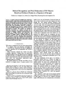
Since fast head movements occur in automotive applications, we tested the capability to track fast head rotations in section IV-B. In section IV-C the gaze of the driver, gathered through head pose and determination of the angular state of the eyeballs, is evaluated defining hit rates on particular gaze regions as tachometer, interior mirror, etc. as typical for automotive conditions. A. Accuracy of the Head Pose To evaluate the accuracy of the proposed head pose estimation algorithm, we use the Biwi Kinect Head Pose Database provided by Fanelli et al. in conjunction with [4]. The database contains of more than 15 thousand frames in 24 sequences. The sequences are acquired with a Microsoft Kinect sensor. 20 people (some were recorded twice - 6 women and 14 men) were recorded while turning their heads, sitting in front of the sensor, at roughly one meter of distance. For each frame a depth image, a color image, the ground truth position is provided. For each sequence the calibration matrices, mapping the depth image pixels to the color image and vice versa are provided, too. The ground truth pose of the test persons are annotated with an accuracy level of 1 degree in angularity and 1 mm deviation in position. Ground truth was annotated using a high accuracy ICP algorithm provided from faceshift [18]. A 3D head model is provided to each of the 20 test subjects as an .obj file. The templates model the raw head shape without any hairstyle, glasses, or earrings. Figure 8 shows Accuracy Head Tracking - Based on 15287 frames 100
90
Correctness [ Percent ]
80
70
Kinect Head Pose Database start with the test person looking straight into the camera. Since our algorithm needs a few frames to initialise, for this reason the classification rate in the center squares is marginally lowered. The results are presented for 15, 10, and 5 degrees tolerance in the figures 9(b), 9(a), and 9(c). Figure 9(d) shows the results of Fanelli et al. for the work published in [4] with an accepted error of 15 degrees. The plot was provided in personal communication [14]. Since the results of Fanelli et al is based on the same database a good comparison could be made. B. Fast Head Movements While driving a car, very fast head movements can occur. Especially if the driver is manoeuvring his car in parking situations or if the driver is unsure or feeling unsafe at crossings, he is turning his head from left to right to make sure that all objects which could possibly cause collision have been seen. Hence, a head tracking application for automotive purposes has to cope with high rotation angle velocities, especially in the yaw direction. We tested the robustness of our algorithm by shaking the head faster and faster in yaw direction. Figure 10 shows a plot of the measured angle velocities. All head movements slower than 4 radians per second could be reliably measured. If the head movements exceeds 4 radians per second in yaw, the head pose is occasionally lost (black lines in figure 10). The head pose is mainly lost for two reasons: First, the initial transformation Tinit for the ICP-step estimating the head pose is based on the previous estimated head pose. If the new head pose differs too much from the last head pose, the initialisation is not good enough to determine the head pose in the current frame. Second, with high velocity movements, the pixels of the depth image, as well as the pixels of the color image exhibit motion blur, resulting in an less accurate input image.
60
50
40
Accuracy Rate - This approach Fanelli et al. [4] Seeman et al. [2] reported through [6] Breitenstein et al. [6] (1)
30 0
2
4
6
8 10 12 Tolerance [ Degrees ]
14
16
18
20
Fig. 8. The correct classification rate depending on the accepted level of inaccuracy in yaw. With an tolerance level of 10 degrees, the head pose was correctly determined in 92% of the input frames. The results of Fanelli et al. and Breitenstein et al. are taken from [4] and [6], respectively. (1) The results of [6] are based on high resolution scans.
the results of our evaluation compared to the results found in [2], [4], and [6]. Accepting a tolerance of 4 degrees in yaw, 82% of the head poses were correctly estimated. With an tolerance level of 10 degrees in yaw, the head pose was correctly determined in 92% of the input frames. Figure 9 shows the accuracy rates partitioned in 15 × 15 degrees squared regions in yaw and pitch. The color of the square represents the amount of frames falling into the particular region. All measurements recorded in the Biwi
C. Driver Gaze Point Evaluation To evaluate the gaze direction, we annotated our data-base with particular regions of interest Straight, Left Mirror, Right Mirror, Interior Mirror, and Tachometer. The data-base contains recordings of drivers specifically looking at the particular regions of interest. Figure 12 shows an plot in pitch and yaw representing the drivers head pose. Considering the driver’s head pose, without the angularities of the eyes, results in an yaw range of −50 to 30 degrees and ±15 degrees in pitch. Taking the angularities of the eyes in consideration, as well, the full 180 degree field of view is covered (compare 12 and 11), supporting our thesis illustrated in figure 1. The rotation of the head is narrow compared to the field of view taking the gaze direction into account. It can be seen, that the driver’s gaze clusters are more focused taking the results of the gaze estimation, rather than the head pose only. V. CONCLUSIONS AND FUTURE WORKS Getting information of the drivers line of sight can enrich the input of various driver assistance systems. However, the
c
IEEE. Personal use of this material is permitted. Permission from IEEE must be obtained for all other uses, in any current or future media, including reprinting/republishing this material for advertising or promotional purposes, creating new collective works, for resale or redistribution to servers or lists, or reuse of any copyrighted component of this work in other works. DOI: http://dx.doi.org/10.1109/ITSC.2012.6338678 Angle Velocity Threshold - Increasing Angle Velocity Test 5 Measured Angle Velocity Angle Velocity Limit Angle Velocity [rad / sec]
4
3
2
1
0
Head Lost
1
(a) Correct classification rates for 10 degrees tolerance.
0 100
110
120
130
140 Time [sec]
150
160
170
180
Fig. 10. Turning the head from left to right in yaw. Head movements slower than 4 radians per second could reliably been tracked. The black markers indicate, if the head position is lost.
Gaze Direction Looking at Regions Of Interest 1
0.5
Pitch [rad]
(b) Correct classification rates for 15 degrees tolerance. 0
-0.5
-1 -1.5
(c) Correct classification rates for 5 degrees tolerance.
Interior Mirror Straight Right Mirror Tacho Left Mirror -1
-0.5
0 Yaw [rad]
0.5
1
1.5
Fig. 11. Gaze Results of the driver looking at the Tachometer, the Left Mirror, the Right Mirror, Straight and the Interior Mirror. There are a few false positive measurements in the upper left corner of the clusters. They gain from the template matching algorithm (see III-C) classifying the eye-brow rather than the iris.
Head Rotation Looking at Particular Regions Of Interest 1
Pitch [rad]
0.5
0
-0.5
(d) Correct classification rates of [4] for 15 degrees tolerance based on the same data-base [14]. Fig. 9. The accuracy rates partitioned in 15 × 15 degrees squared regions in yaw and pitch. Figure 9(a), 9(b), and 9(c) are results of this algorithm whereas figure 9(d) represents the work of Fanelli et al. in [4].
-1 -1.5
Interior Mirror Straight Right Mirror Tacho Left Mirror -1
-0.5
0 Yaw [rad]
0.5
1
1.5
Fig. 12. Measured head rotation angles of the driver looking at particular regions of interest. The value range is narrow, compared with the value range of the line of gaze (figure 11).
c
IEEE. Personal use of this material is permitted. Permission from IEEE must be obtained for all other uses, in any current or future media, including reprinting/republishing this material for advertising or promotional purposes, creating new collective works, for resale or redistribution to servers or lists, or reuse of any copyrighted component of this work in other works. DOI: http://dx.doi.org/10.1109/ITSC.2012.6338678
demands of an gaze tracking system used for automotive applications are not easy to satisfy. In this work, an approach to identify the drivers line of sight was introduced. It estimates the pose of the head as a preprocessing step and ascertains the angularities of the eyes subsequently. The head pose was determined using an ICP algorithm matching point clouds gained through a Microsoft Kinect sensor. The correspondence search of the ICP algorithm (nearest neighbour) was implemented by means of an projection into the depth image, making the algorithm fast and keeping real-time conditions at 30 Hz on an off-the-shelf desktop CPU. The accuracy of the head pose was approved to be correct in 92 percent of the frames accepting a tolerance of 10 degrees in yaw. Tightening the tolerance level of 4 degrees, still 82% of the frames could be correctly classified. In automotive applications, fast head movements in occur. The proposed system can handle head rotations with the speed of up to 4 radians per second. The angularity of the eyes was estimated by generating a projected image according to the head pose and finding the center of the iris in the projected image. By combining the eye posture and the head pose, the direction of gaze could be determined in an more focused way. The drivers gaze could be successfully mapped to particular regions of interest (Tachometer, Left Mirror, Right Mirror, Straight, Interior Mirror). As future work, we focus on the automatic generation of the used face template and the inference of driver actions based on the ascertained gaze direction. VI. ACKNOWLEDGEMENTS Thanks to Gabrielle Fanelli for providing extra data and evaluation results of his work introduced in [4]. R EFERENCES [1] Erik Murphy-Chutorian and Mohan Manubhai Trivedi : Head Pose Estimation in Computer Vision: A survey , IEEE Transactions on Pattern Analysis and Machine Intelligence - 2008 [2] Edgar Seemann, Kai Nickel and Rainer Stiefelhagen: Head Pose Estimation Using Stereo Vision For Human-Robot Interaction , Sixth IEEE International Conference on Automatic Face and Gesture Recognition - 2004 [3] Real Time Head Pose Estimation with Random Regression Forests: G. Fanelli and J. Gall and L. Van Gool, CVPR Computer Vision and Pattern Recognition - 2011 [4] Real Time Head Pose Estimation from Consumer Depth Cameras: G. Fanelli and T. Weise and J. Gall and L. Van Gool, 33rd Annual Symposium of the German Association for Pattern Recognition (DAGM’11) - 2011 [5] Fast 3D Scanning with Automatic Motion Compensation: T. Weise and B. Leibe and L. Van Gool, IEEE Conference on Computer Vision and Pattern Recognition (CVPR’07) - 2007 [6] Real-Time Face Pose Estimation from Single Range Images: Michael D. Breitenstein and Daniel Kuettel and Thibaut Weise and Luc van Gool and Hanspeter Pfister, IEEE Conference on Computer Vision and Pattern Recognition 2008 [7] Realtime Performance-based Facial Animation: Thibaut Weise and Sofien Bouaziz and Hao Li and Mark Pauly ACM Transactions on Graphics (Proceedings SIGGRAPH 2011) - 2011 [8] Passive driver gaze tracking with active appearance models: Takahiro Ishikawa and Simon Baker and Iain Matthews and Takeo Kanade In Proceedings of the 11th World Congress on Intelligent Transportation Systems - 2004 [9] On Eye Gaze Determination via Iris Contour: todod Jing-Gang Wang and Eric Sung and Ronda Venkateswarlu, MVA2000 - IAPR Workshop on Machine Vision Applications - 2000
[10] A single camera eye-gaze tracking system with free head motion: Hennessey, C and Noureddin, B and Lawrence, P, ACM Press - 2006 [11] FreeGaze: a gaze tracking system for everyday gaze interaction: Ohno, T and Mukawa, N and Yoshikawa, A, Proc Symposium on ETRA 2002 [12] A Precise Eye-Gaze Detection and Tracking System: Perez, A and Cordoba, M L and Garcia, A and Mendez, R and Munoz, M L and Pedraza, J L and Sanchez, F, V. Skala, Ed. System - 2003 [13] A method for registration of 3-d shapes: P. Besl and N. McKay, PAMI - 1992 [14] G. Fanelli Personal communication per eMail - March 2012 [15] The OpenCV Library: Bradski, G., Dr. Dobb’s Journal of Software Tools - 2000 [16] Fast global registration of 3D sampled surfaces using a multi-zbuffer technique: R. Benjemaa and F. Schmitt, IEEE International Conference on Recent Advances in 3-D Digital Imaging and Modelling - 1997 [17] Efficient variants of the icp algorithm: Szymon Rusinkiewicz and Marc Levoy, International Conference on 3-D Digital Imaging and Modelling - 2001 [18] faceshift.com: Thibaut Weise and Hao Li and Sofien Bouaziz and Mark Pauly, accessed 03 - 2011 [19] Looking-in and looking-out of a vehicle: Computer-vision-based enhanced vehicle safety : Mohan Manubhai and Trivedi and Tarak G and Joel Mccall, IEEE Trans. Intell. Transp. Syst - 2007