JOURNAL OF MULTIMEDIA, VOL. 9, NO. 1, JANUARY 2014
159
DWT-Based Multisource Image Fusion Using Spatial Frequency and Simplified Pulse Coupled Neural Network Nianyi Wang 1, 2 1. School of Information Science and Engineering, Lanzhou University, Lanzhou 730000, China 2. School of Mathematics and Computer Science Institute, Northwest University for Nationalities, Lanzhou 730000, China Email:
[email protected]
Yide Ma* School of Information Science and Engineering, Lanzhou University, Lanzhou 730000, China *Corresponding Author, Email:
[email protected]
Weilan Wang School of Mathematics and Computer Science Institute, Northwest University for Nationalities, Lanzhou 730000, China Email:
[email protected]
Abstract—In this paper, we present a new discrete wavelet transform (DWT)-based multisource image fusion algorithm using spatial frequency and a simplified pulse coupled neural network model named spiking cortical model (SCM). The multiscale decomposition and multi-resolution representation characteristics of DWT are associated with global coupling and pulse synchronization features of SCM. Firstly, source images are decomposed into low frequency sub-bands and high frequency sub-bands by DWT. Secondly, considering human visual system characteristics, two different fusion rules are used to fuse low and high frequency sub-bands respectively. Maximum selection rule (MSR) is used to fuse low frequency coefficients. As to high frequency subband coefficients, spatial frequency (SF) is calculated and then imputed into SCM to motivate neural network rather than inputting coefficients value directly, and then the time matrix of SCM is set as criteria to select coefficients of high frequency subband. The effectiveness of the proposed algorithm is achieved by the comparison with existing fusion methods. Index Terms—Multisource Image Fusion; Spiking Cortical Model (SCM); Discrete Wavelet Transform (DWT); Simplified PCNN; Spatial Frequency
I.
INTRODUCTION
Image fusion extracts information from two or more source images into a single composite image. The fused image provides a more informative and comprehensive description, and is more suitable for human visual perception. There are many kinds of image fusion methods. Along them, those methods that based on multiscale decomposition (MSD) of source images become more popular and important tools in recent years. MSD methods decompose source images into high frequency and low frequency subbands. Detailed and © 2014 ACADEMY PUBLISHER doi:10.4304/jmm.9.1.159-165
coarse features remain in two types of subbands, respectively [1]. New MSD methods are introduced in image fusion, such as Curvelet [2], Ridgelet [3], Contourlet, and Ripplet [4], etc. In MSD domain, the discrete wavelet transform (DWT) becomes one of the most popular methods. The DWT is suitable for image fusion for the following reasons: (1) It is a multiscale method that well suited to manage different image resolutions. (2) The DWT allows image decomposition in different levels of coefficients to preserve more image information. (3) Coefficients coming from different images can be combined to obtain new coefficients, so that the information in original images is collected. (4) Once coefficients are merged, the final fused image is achieved through the inverse discrete wavelets transform (IDWT), where the information in the merged coefficients is also preserved [5]. In the DWT based image fusion, the key step is to define a fusion rule to create a new composite Multi-resolution representation. Up to now, the widely used fusion rule is the maximum selection (MS) scheme [6]. This simple scheme just selects the largest absolute wavelet coefficient at each location from input images as the coefficient at the location in the fused image. However, as we know that noise and artifacts usually have higher salient features in the image, therefore, this method is sensitive to noise and artifacts. Researchers widely discussed and proposed some solutions to this problem [7]. As one of the third generation artificial neural networks, Pulse coupled neural network (PCNN) is another important image processing tool. It is a visual cortex-inspired network characterized by global coupling and pulse synchronization of neurons [8], and has been widely applied in intelligent computing including image
160
JOURNAL OF MULTIMEDIA, VOL. 9, NO. 1, JANUARY 2014
processing. Spiking cortical model (SCM) is one of the simplified PCNN models that is mainly derived from Eckhorn’s model and deduced from primate visual cortex, and also has been proved as an effective image processing tool [9]. In recent years, researchers proposed several image fusion algorithms based on transform domain and PCNN. For the first time, Mary Lou Padgett and John L. Johnson used wavelet analysis along with PCNN to separate signal from background noise effectively. Literature [10] integrated PCNN and Wavelet into a decision system to separate sensor faults from targets, and then recalibrated the target detection and identification procedures. In literature [11], PCNN is based on mufti-resolution decomposition of wavelet for extracting the features of interest in images by eliminating noise. Literature [12] combined wavelet packet analysis (WPA) with PCNN together in image fusion algorithm. Literature [13] proposed a multifocus image fusion algorithm based on multiscale products of lifting stationary wavelet transform (LSWT) and the improved pulse coupled neural network (PCNN). Literature [14] discussed PCNN Forecasting Model Based on Wavelet Transform. Literature [15] presents a multi-source image fusion scheme based on lifting stationary wavelet transform (LSWT) and a novel dual-channel PCNN. However, in most of these PCNN and wavelet based algorithms, the value of single pixel in spatial or MSD domain is directly used to motivate one neuron. In fact, human’s visual system in most time is sensitive to edges, directional features, etc. So, using single pixel in MSD domain purely is not enough. It is necessary to use spatial frequency, which stands for gradient energy in wavelet domain, to motivate PCNN neurons [9], [16], [17]. Another question should be considered in the above mentioned discussion is the computation complexity and time consuming of PCNN. In this paper, motivated by the fact that the key challenge of DWT based image fusion is how to select proper coefficients of subbands from source images after DWT decomposition, a new method of image fusion using the discrete wavelet transform (DWT) and spiking cortical model (SCM) is proposed. The main contribution of this paper is that after executing DWT, the coefficients in low frequency sub-bands and high frequency sub-bands are processed by using different fusion rules. The performance evaluation of the proposed fusion approach is verified, when compared to that of several existing fusion methods. II.
SPIKING CORTICAL MODEL (SCM) AND DISCRETE WAVELET TRANSFORM (DWT)
A. Spiking Cortical Model Like traditional PCNN models, each neuron in SCM consists of three parts: receptive field, modulation field, and pulse generator. In the SCM model, each neuron is directly tied to image pixel. And neuron iteratively processes signals feeding from inputs of receptive field and linking inputs to produce a pulse. Similarities in the input pixels cause the associated neurons to fire © 2014 ACADEMY PUBLISHER
synchronously. In the linking modulation field, it gathers the outputs from two channels: The linking modulation is made by adding a bias to the linking, and multiplying this by the feeding inputs. The resultant quantity is called the internal state of a neuron. The pulse generator generates the pulse depending on the internal state and the threshold, which depending on the output of the neuron. Literature [9] discussed SCM’s features and its application in image processing in detail. SCM decreased computation complexity and is much less time consuming than PCNN. The SCM neuron model is shown in Figure 1. Outputs of neighboring neurons
· · · · · ·
Eij
+1
Ykl
h g
W
Σ
f 1
External Sij stimulus
Receptive field
×
Σ
Modulating product Modulation field
Uij
0
Yij
Pulse generator
Figure 1. SCM model
Figure 2 shows how the SCM processes the original stimuli. Higher intensities of stimulus correspond to high internal activity. For two equal threshold intervals △E1 and △E2, the high stimuli would be processed coarser by spending less time marked as △t1, and conversely, the lower intensities of stimulus are processed more accurately by spending more time marked as △t2. Similarly, Weber–Fechner law shows that human visual system processes contrast varying with intensities. It is much less sensitive to high intensities than to low intensities. Human visual system has a high sensitivity for low intensities of stimulus, but low sensitivity for high intensities. Thus, the time matrix of SCM describes the human visual perception well [9]. Figure 3 shows that In the SCM model, each neuron is directly tied to image pixel.
Figure 2. Process of different intensity of a stimulus in SCM model
B. Discrete Wavelet Transform (DWT) The DWT is identical to a hierarchical sub band system where the sub bands are logarithmically spaced in frequency and represent octave-band decomposition. DWT is a new method for multiresolution analysis, by which an image can be decomposed into the lowest approximation and several details at different scales and in different directions. The lowest approximation contains the average information and most energy of the image,
JOURNAL OF MULTIMEDIA, VOL. 9, NO. 1, JANUARY 2014
161
while details contain edges or high frequency information at different scales and in different directions [18].
Figure 3. Connection model of SCM neuron
By applying DWT, image is actually divided, i.e., decomposed into four subbands and critically sub sampled as shown in Figure 4 (a). These four sub bands arise from separable applications of vertical and horizontal filters. The sub bands labeled LH1, HL1 and HH1 represent the finest scale wavelet coefficients, i.e., detail images while the sub band LL1 corresponds to coarse level coefficients, i.e., approximation image. To obtain the next coarse level of wavelet coefficients, the sub band LL1 alone is further decomposed and critically sampled. This results in two-level wavelet decomposition as shown in Figure 4 (b). Similarly, to obtain further decomposition, LL2 is used. This process continues until some final scale is reached. The values or transformed coefficients in approximation and detail images (sub-band images) are essential features, which are useful for image fusion [19].
Figure 4. Image decomposition: (a) One level (b) Two level
III.
PROPOSED FUSION METHOD
A. Fusion Scheme Firstly, source images are decomposed into low frequency sub-bands and high frequency sub-bands by DWT. Secondly, considering human visual system characteristics, two different fusion rules are used to fuse low and high frequency sub-bands respectively. Maximum selection rule (MSR) is used to fuse low frequency coefficients. As to high frequency subband coefficients, spatial frequency (SF) is calculated and then imputed into SCM to motivate neural network rather than inputting coefficients value directly, and then the time matrix of SCM is set as criteria to select coefficients of high frequency subband. The SCM we use in this paper can be expressed as:
U ij (n) = fU ij (n 1) + Sij Wijkl Ykl (n 1) Sij (1) kl
Eij (n) = gEij (n 1) hYij (n 1)
© 2014 ACADEMY PUBLISHER
(2)
1/ (1 exp( (U ij (n) Eij (n)))) 0.5 1, (3) Yij (n) 0,otherwise where Uij(n) is internal activity, Sij is a stimulus, Yij(n) is output, Eij(n) is dynamic threshold, Wijkl is synaptic weight matrix applied to the linking field, f and g are decay constants, h is threshold magnitude coefficient, γ is a parameter of sigmoid function. The nonlinearity of sigmoid function can be used to generate pulse. Sigmoid curve has an “S” shape, with its slope increasing as γ increases. For DWT, if an image is transformed into L levels, we will get (3L+1) subbands, one approximation subband or baseband Cj of low frequency and 3L subbands Dh, Dv and Dd of high frequency. Let f (x, y) be an original image, denoted by C0, 2-D DWT can be performed as follows:
C j +1 =HC j H' h D j 1 =GC j H' ( j 0,1,..., J 1) v D j 1 =HC j G ' d D j 1 =GC j G '
(4)
where h, v, d represent horizontal, vertical and diagonal respectively. H’ and G’ is conjugate transpose of H and G. J is the decomposition level. Reconstruction formula is:
C j 1 =H'C j H+G'D hj H+H'Dvj G+G'D dj G ( j 0,1,..., J 1)
(5)
B. Fusion Step Let A and B be two source images, F be the fused image, (i, j) denotes spatial location. K denotes coefficient. Step 1) Decompose the registered source images A and B respectively into one low frequency sub-image and a series of high frequency sub-images via DWT. Step 2) Select low frequency coefficients K FL of fused image F from A and B by using maximum selection rule (MSR) [6] as follow: A K i, j , K FL i, j LB K L i, j ,
K AL i, j K BL i, j (6) K AL i, j < K BL i, j
Step 3) Select high frequency coefficient K FH of fused image F from A and B by using SCM. As human vision system is sensitive to features such as edges, contours etc., so instead of using SCM directly, spatial frequency (SF) is considered as the gradient features of images to motivate SCM networks [20]. Calculate SF of each high frequency subband as:
SFi , j ( I i , j I i 1, j )2 ( I i , j I i , j 1 )2
(7)
where SFi,j, denotes the SF of the pixel that located at (i,j), and I,i,j denotes the coefficient of the pixel that located at (i,j).
162
JOURNAL OF MULTIMEDIA, VOL. 9, NO. 1, JANUARY 2014
Figure 5. Fusion results of image group 1: (a) original infrared image; (b) original visible image; Fused image using (c) Averaging method, (d) PCA, (e) DWT, (f) Laplacian pyramid (LP), (g) morphological pyramid (MP), (h) our proposed method. Infrared light can pass right through objects that stop visible light entirely, but it will be stopped by some things that let visible light through.
SF in each high frequency subbands are set as feeding input of SCM and input into SCM to motivate neurons and generate pulse of neurons by using formula (1)-(3). In SCM network mechanism, if Yi,j(n) is equal to 1, it means the neuron will generate a pulse, or we can say one firing occurs. The sum of Yi,j(n) in n iteration (namely the firing times) is defined as Ti,j(n) to represent the image information. Rather than Yi,j(n), researchers often analyze T i,j (n), because neighboring coefficients with similar features representing similar firing times in a given iteration times. Ti,j(n) is defined as:
Ti , j n Ti , j n 1 Yi , j (n)
(8)
In this paper, we set firing times Ti,j(n) as criteria to calculate coefficients of each high frequency subband as follow:
K A i, j ,Ti ,Aj n Ti ,Bj n K FH i, j HB K H i, j ,otherwise
(9)
Step 4) Apply Inverse DWT to get the fused image. IV.
RESULTS AND DISCUSSION
In this paper, quantitative assessment of different image fusion algorithms are compared using following evaluation criteria, which have been proved to be effective to a great degree [21]. 1. Mutual information (MI): MI [22] can be used to measure amount of information transferred from source images to final fused image. Fusion performance would be better and better with MI increasing. 2. Standard deviation (SD): SD indicates deviation degree between grey values of pixels and the average one of the fused image. It measures the contrast of the fused image. An image with high contrast would have a high standard deviation [23]. 3. Energy of laplacian (EOL): EOL is another focus measure for analyzing high spatial frequencies associated with image border sharpness, and also is one of the useful indices to describe clarity of image [24]. 4. QAB/F: QAB/F is an index of edge information preservation. It was proposed by C. S. Xydeas et al. as an objective image fusion performance measure [25]. To evaluate the performance of the proposed image fusion approach, three different groups of multi-source © 2014 ACADEMY PUBLISHER
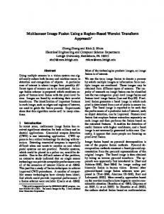
images are considered (see Figure 5(a, b), Figure 6(a, b), Figure 7(a, b)). Figure 5 (a) and Figure 6(a) are original infrared images, Figure 5 (b) and Figure 6 (b) are original visible images, Figure 7 (a) is original coronal FDG image, and Figure 7 (b) is original coronal MR-T1 image. Infrared light has a longer wavelength and lower energy than visible light. Infrared light can pass right through objects that stop visible light entirely, but it will be stopped by some things that let visible light through. From Figure 5 and Figure 6, we can see that infrared images can display living creature clearly (see Figure 5 (a) and Figure 6 (a)), while visible image display surrounding environment more clearly. In medical imaging, CT image shows structures of bone, while MR image shows areas of soft tissue. All images have 256-level gray scale. It can be seen that due to various imaging principle and environment, the source images with different modality contain complementary information. For all these image groups, results of proposed fusion framework are compared with Averaging method, PCA method, discrete wavelet transform (DWT) with DBSS (2, 2), Laplacian pyramid (LP), morphological pyramid (MP). Parameters of these methods are set by: pyramid level = 4, selection rules: high-pass = select max, lowpass = average. The visual comparison for fused images according to different fusion algorithms are shown in Figure 5(c–h), Figure 6(c–h), Figure 7(c–h) [26]. From the fusion results displayed in Figure 5-7, it is clear that the Averaging and PCA algorithm lose too many image details and provide poor fusion results compared with other four algorithms. In Figure 5 (d), it is hard to find the man in the fused image and in Figure 6 (d) the detail of sky disappears too. This is because both of them have no scale selectivity. This limitation is modified in DWT, LP and MP. Morphological pyramid (MP) provides satisfactory fusion result, but it always brings fake image information and result in block effect. We can easily find block effect and fake image information in Figure 5 (g) (see the roof part of the building) and Figure 6 (g) (see the outline part of the trees). The remaining DWT, Laplacian pyramid (LP) and our proposed method achieved similar fusion effect. Visual quality of DWT, LP and our proposed method are clearly superior to other three methods. From subjective observation, we can see
JOURNAL OF MULTIMEDIA, VOL. 9, NO. 1, JANUARY 2014
163
Figure 6. Fusion results of image group 2: (a) original infrared image; (b) original visible image; Fused image using (c) Averaging method, (d) PCA, (e) DWT, (f) Laplacian pyramid (LP), (g) morphological pyramid (MP), (h) our proposed method.
Figure 7. Fusion results of image group 2: (a) original coronal FDG image; (b) original coronal MR-T1 image; Fused image using (c) Averaging method, (d) PCA, (e) DWT, (f) Laplacian pyramid (LP), (g) morphological pyramid (MP), (h) our proposed method. TABLE I. Fusion
COMPARISON OF SIX FUSION METHODS ON THREE IMAGE GROUPS
Evaluation indices MI SD EOL QAB/F
Averaging 0.9129 7.9551 0.3693 0.0130
PCA 2.2931 9.5364 1.1488 0.0301
DWT 0.7247 8.2123 1.3183 0.0243
LP 0.7849 8.4648 1.3937 0.0243
MP 0.6840 8.4914 2.3734 0.0263
Proposed 0.9849 8.2982 1.4098 0.0396
Image group 2
MI SD EOL QAB/F
1.9918 9.5700 0.5514 0.0412
2.8069 8.1862 1.7836 0.0686
1.6301 9.5378 1.2200 0.0604
1.6513 9.5252 1.1792 0.0611
1.2697 9.3777 1.2399 0.0595
2.9546 9.5417 1.1413 0.0697
Image group 3
MI SD EOL QAB/F
2.1655 10.8812 0.3045 0.3891
2.4311 10.8528 0.3106 0.4429
2.1098 10.4732 0.9071 0.4712
2.1642 10.6655 0.9242 0.5911
2. 3002 10.3067 1.1096 0.4847
2.5234 10.7904 0.9844 0.6543
Image group 1
that the proposed algorithm is effective in multisource image fusion. One of the reasons behind the performance of the proposed method is the human visual characteristics of SCM, which brings high contrast and more informative details to fused images. V.
CONCLUSIONS
In this paper, we proposed a new multisource image fusion algorithm based on SCM and DWT. The proposed method is suitable for fusion of multisource image. The multiscale decomposition and multi-resolution representation characteristics of DWT are associated with
© 2014 ACADEMY PUBLISHER
global coupling and pulse synchronization features of SCM. Considering the human visual system characteristics, two different fusion rules are used to fuse the low and high frequency sub-bands respectively. Spatial frequency is applied to motivate SCM network rather than using coefficients value directly. The efficiency of the proposed algorithm is achieved by the comparison with existing fusion methods. Experimental data proved that the proposed method can decrease image artifacts and preserve edge information. The statistical comparisons prove the effectiveness of the proposed fusion method.
164
JOURNAL OF MULTIMEDIA, VOL. 9, NO. 1, JANUARY 2014
Figure 8. Fusion methods comparison on three image groups: (a) MI comparison; (b) SD comparison; (c) EOL comparison; (d) QAB/F comparison.
ACKNOWLEDGEMENT The authors would like to thank the anonymous reviewers and editors for their invaluable suggestions. This work was jointly supported by the National Natural Science Foundation of China (No. 61175012, 61162021, 61201422), Science and Technology Innovation Project of Ministry of Culture No [2011] 820, and Innovative Team Subsidize of Northwest University for Nationalities. REFERENCES [1] Zhang, Z., & Blum, R. S. “A categorization of multiscale-decomposition-based image fusion schemes with a performance study for a digital camera application.” Proceedings of the IEEE, Vol. 87, No. 8, pp. 1315-1326, 1999. [2] Starck, J. L., Candès, E. J., & Donoho, D. L. “The curvelet transform for image denoising.” IEEE Transactions on Image Processing, Vol. 11, No. 6, pp. 670-684, 2002. [3] Candes, E. J. Ridgelets: theory and applications (Doctoral dissertation, Stanford University), 1998. [4] Li, S., Yang, B., & Hu, J. “Performance comparison of different multi-resolution transforms for image fusion.” Information Fusion, Vol. 12, No. 2, pp. 74-84, 2011. [5] Pajares, Gonzalo, and Jesús Manuel de la Cruz. "A wavelet-based image fusion tutorial." Pattern recognition, Vol. 37, No. 9, pp. 1855-1872, 2004. [6] Li, Hui, B. S. Manjunath, and Sanjit K. Mitra. "Multisensor image fusion using the wavelet transform." Graphical models and image processing, Vol. 57, No. 3, pp. 235-245, 1995.
© 2014 ACADEMY PUBLISHER
[7] Yang, Yong. "A Novel DWT Based Multi-focus Image Fusion Method." Procedia engineering, Vol. 24, pp. 177-181, 2011. [8] Johnson, J. L., & Padgett, M. L. “PCNN models and applications”. IEEE Transactions on Neural Networks, Vol. 10, No. 3, pp. 480-498, 1999. [9] Zhan, K., Zhang, H., & Ma, Y. “New spiking cortical model for invariant texture retrieval and image processing.” IEEE Transactions on Neural Networks, Vol. 20, No. 12, pp. 1980-1986, 2009. [10] Padgett, Mary Lou, T. A. Roppel, and J. L. Johnson. "Pulse coupled neural networks (PCNN), wavelets and radial basis functions: olfactory sensor applications." Neural Networks Proceedings, IEEE World Congress on Computational Intelligence. The 1998 IEEE International Joint Conference on. Vol. 3, 1998. [11] Berthe, Kya, and Yang Yang. "Automatic edge and target extraction base on pulse-couple neuron networks wavelet theory (PCNNW)." Info-tech and Info-net, 2001. Proceedings. ICII 2001-Beijing. 2001 International Conferences on, Vol. 3, 2001. [12] Li, Wei, and Xue-Feng Zhu. "A new image fusion algorithm based on wavelet packet analysis and PCNN." Machine Learning and Cybernetics, 2005. Proceedings of 2005 International Conference on, Vol. 9, 2005. [13] Chai, Y., H. F. Li, and M. Y. Guo. "Multifocus image fusion scheme based on features of multiscale products and PCNN in lifting stationary wavelet domain." Optics Communications, Vol. 284, No. 5, pp. 1146-1158, 2011. [14] Qiang Fu, Yan Feng, Dengchao Feng. "PCNN Forecasting Model Based on Wavelet Transform and Its Application." [15] Chai, Y., H. F. Li, and J. F. Qu. "Image fusion scheme using a novel dual-channel PCNN in lifting stationary wavelet domain." Optics Communications, Vol. 283, No. 19, pp. 3591-3602, 2010.
JOURNAL OF MULTIMEDIA, VOL. 9, NO. 1, JANUARY 2014
[16] Qu, X., & Yan, J. “Image fusion algorithm based on spatial frequency-motivated pulse coupled neural networks in nonsubsampled contourlet transform domain.” Acta Automatica Sinica, Vol. 34, No. 12, pp. 1508-1514, 2008. [17] Das, S., & Kundu, M. K. “NSCT-based multimodal medical image fusion using pulse-coupled neural network and modified spatial frequency.” Medical and Biological Engineering and Computing, Vol. 50, No. 10, pp. 1105-1114, 2012. [18] Wang, Wei-Wei, Peng-Lang Shui, and Guo-Xiang Song. "Multifocus image fusion in wavelet domain." Machine Learning and Cybernetics, 2003 International Conference on, Vol. 5, 2003. [19] Arivazhagan, S., L. Ganesan, and TG Subash Kumar. "A modified statistical approach for image fusion using wavelet transform." Signal, image and video processing, Vol. 3, No. 2, pp. 137-144, 2009. [20] Eskicioglu, A. M., & Fisher, P. S. “Image quality measures and their performance.” IEEE Transactions on Communications, Vol. 43, No. 12, pp. 2959-2965, 1995. [21] Bhatnagar, G., Jonathan Wu, Q. M., & Liu, Z. “Human visual system inspired multi-modal medical image fusion framework.” Expert Systems with Applications, 2012. [22] Qu, G., Zhang, D., & Yan, P. “Information measure for performance of image fusion.” Electronics letters, Vol. 38, No. 7, pp. 313-315, 2002. [23] Chang, Dah-Chung, and Wen-Rong Wu. "Image contrast enhancement based on a histogram transformation of local standard deviation." Medical Imaging, IEEE Transactions on, Vol. 17, No. 4, pp. 518-531, 1998. [24] Aslantas, V., and R. Kurban. "A comparison of criterion functions for fusion of multi-focus noisy images." Optics Communications, Vol. 282, No. 16, pp. 3231-3242, 2009. [25] Xydeas, C. S., & Petrovic, V. “Objective image fusion performance measure.” Electronics Letters, Vol. 36, No. 4, pp. 308-309, 2000. [26] Wang, N., Ma, Y., Zhan, K., & Yuan, M. "Multimodal Medical Image Fusion Framework Based on Simplified PCNN in Nonsubsampled Contourlet Transform Domain." Journal of Multimedia, Vol. 8, No. 3, pp. 270-276, 2013.
© 2014 ACADEMY PUBLISHER
165
[27] Nianyi Wang, Weilan Wang, and Xiaoran Guo. "Multisource Image Fusion Based on DWT and Simplified Pulse Coupled Neural Network." Applied Mechanics and Materials, in press.
Nianyi Wang received the B.S. degree in computer science from Lanzhou University, Gansu, China in 2002, and received the M. S. degree in computer application technology from Lanzhou University in 2007. He is currently a lecturer in the School of Mathematics and Computer Science Institute, Northwest University for Nationalities. He is currently pursuing the Ph.D. degree in radio physics at Lanzhou University. His current research interests include artificial neural networks, image processing, and pattern recognition. Yide Ma received the B.S. and M.S. degrees in radio technology from Chengdu University of Engineering Science and Technology, Sichuan, China, in 1984 and 1988, respectively. He received the Ph. D. degree from the Department of Life Science, Lanzhou University, Gansu, China, in 2001. He is currently a Professor in the School of Information Science and Engineering, Lanzhou University. He has published more than 50 papers in major journals and international conferences and several textbooks, including Principle and Application of Pulse Coupled Neural Network (Beijing: Science Press, 2006), and Principle and Application of Microcomputer (Beijing: Science Press, 2006). His current research interests include artificial neural networks, digital image processing, pattern recognition, digital signal processing, and computer vision. Weilan Wang is currently a professor in the School of Mathematics and Computer Science Institute, Northwest University for Nationalities. Her current research interests include image processing, pattern recognition, Tibetan information processing, digital protection of Thangka image.